Assignment 08
Embedded Programming
Assignment:
Read a microcontroller datasheet. Program your board to do something, with as many different programming languages and environments as possible.
Learning outcomes:
- Identify relevant information in a microcontroller data sheet
- Implement programming protocols
Have you:
- [ ] Documented what you learned from reading a microcontroller datasheet. What questions do you have? What would you like to learn more about?
- [ ] Programmed your board
- [ ] Described the programming process(es) you used
- [ ] Included your code
This week's recitation
As part of my final project I developed an incremental strategy to fulfill my project's firmware. So I wrote down the next steps:
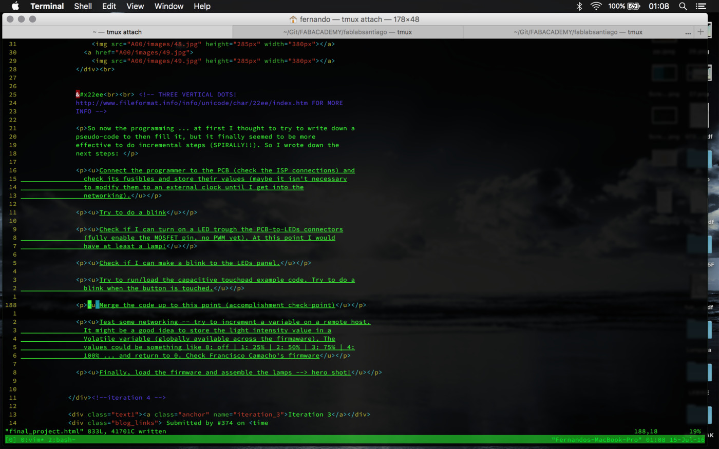
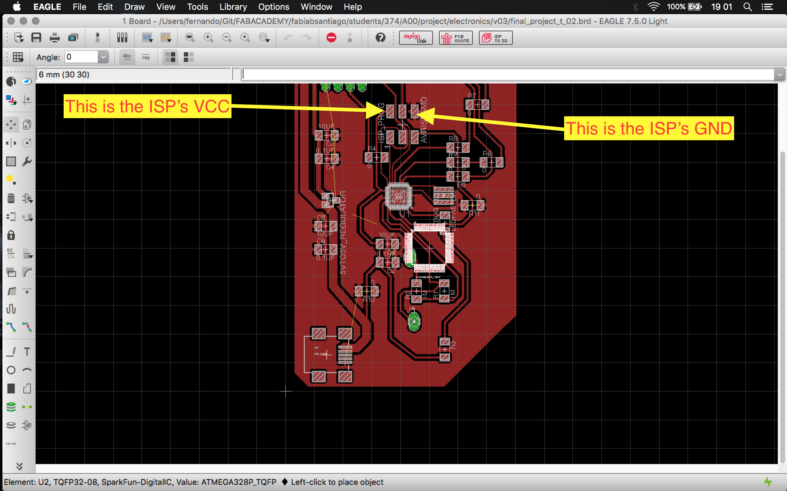
Connect the programmer to the PCB (check the ISP connections) and check its fusibles and store their values (maybe it isn't necessary to modify them to an external clock until I get into the networking).
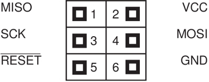
These are the ISP reference connection pins:
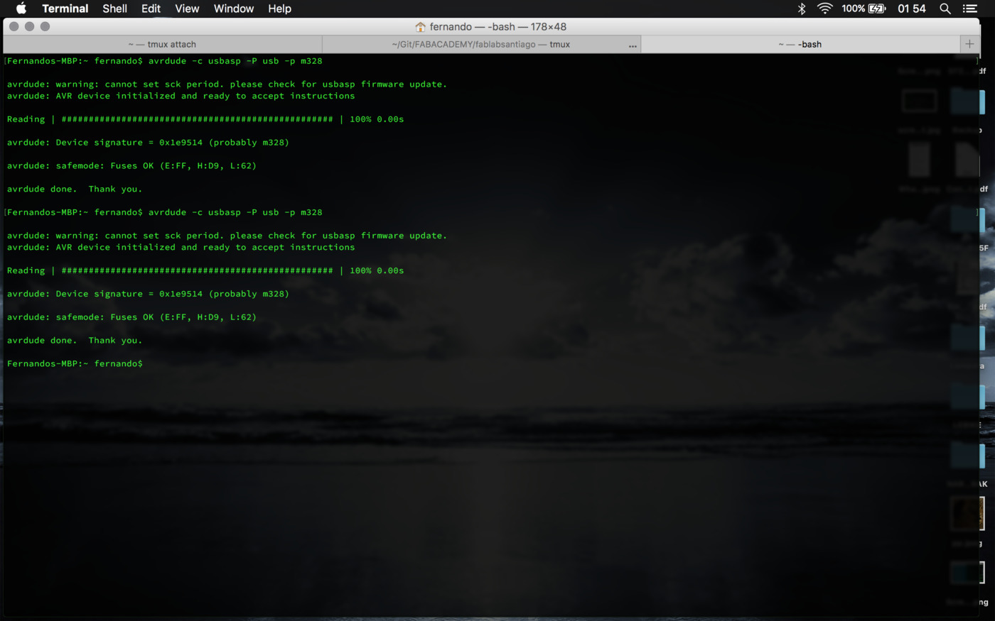
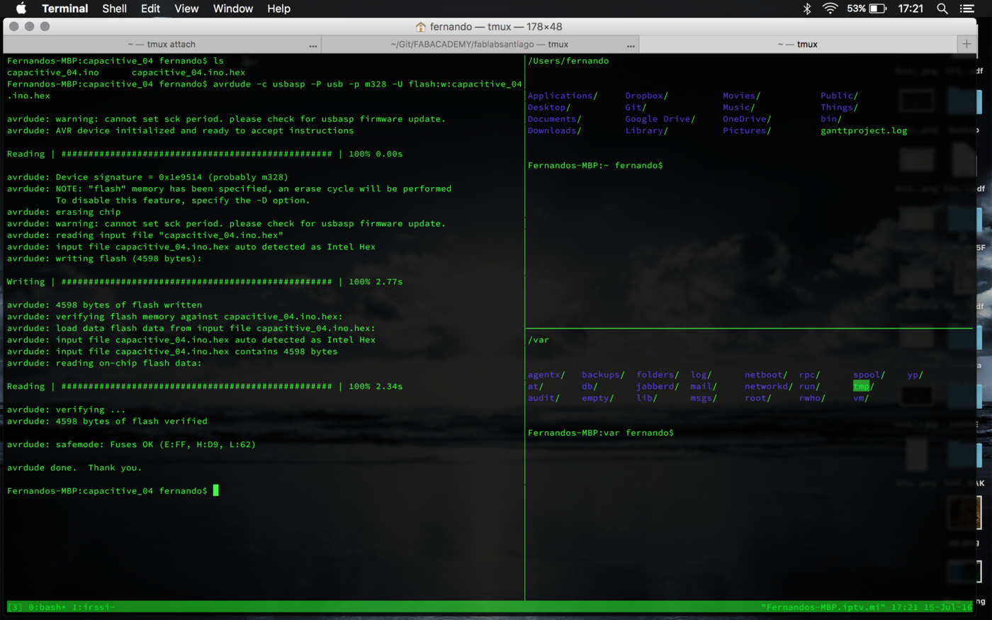
Success! by running 'avrdude -c usbasp -P usb -p m328' the programmer talked to both ICs. The fuses are E:FF, H:D9 and L:62.
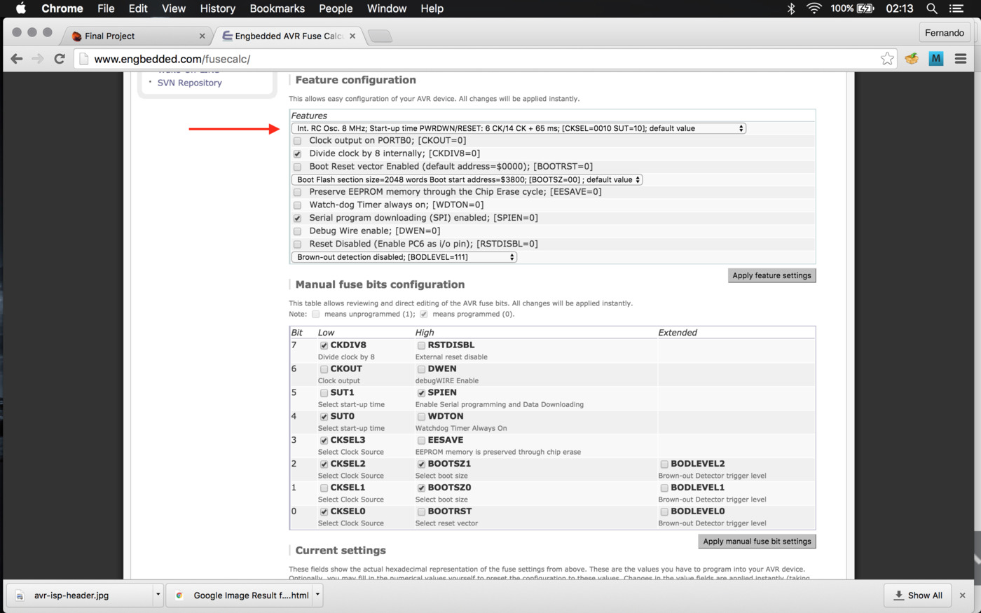
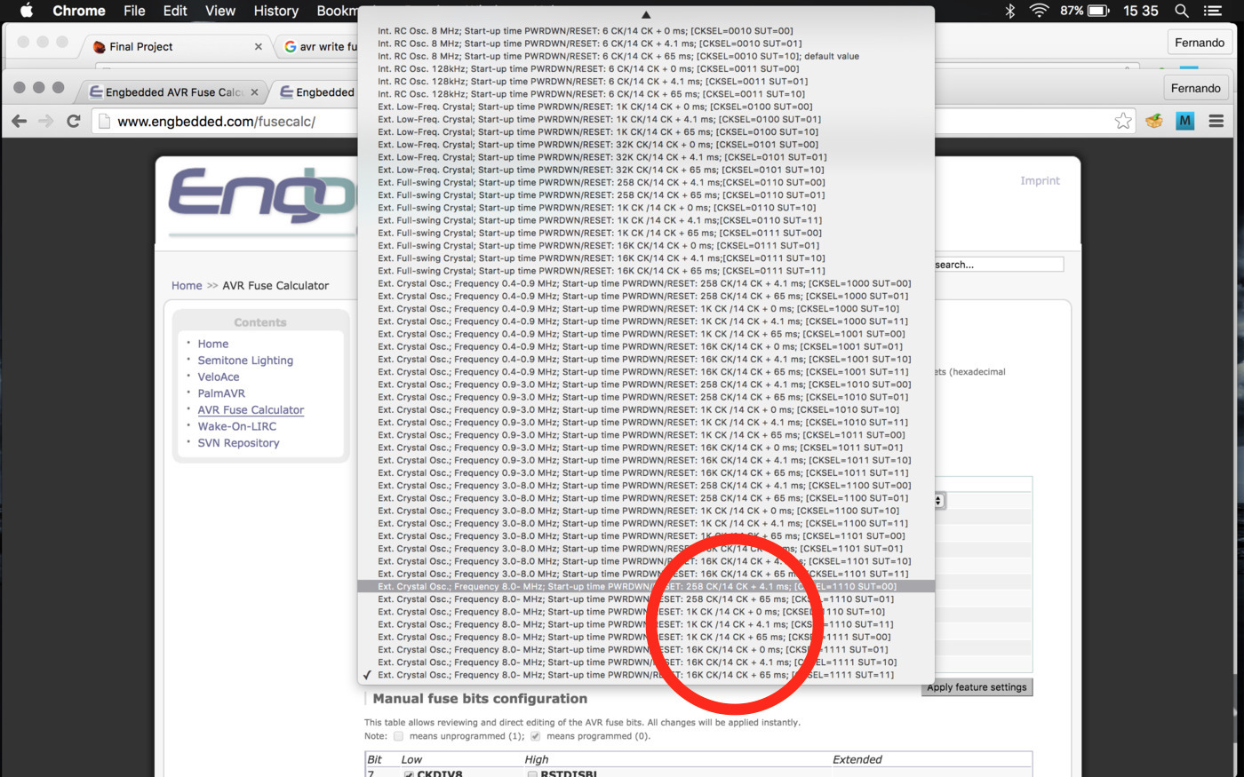
If I check the AVR Fuse calculator (note that there's only ATmega328P on the list and that avrdude distincts with the ATmega328) for this fuses they mean that the ICs are (still) configured with the internal clock (8MHz). The other parameters are no relevant this far (hope so).
Try to do a blink
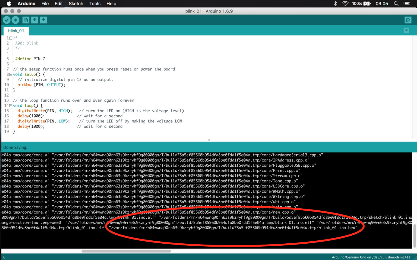
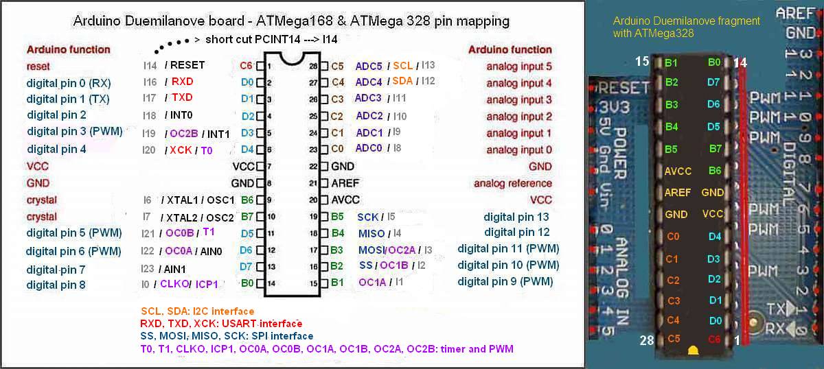
According to the schematics the onboard LED is plugged to the PD2 pin, which correspond to the "Digital Pin 2" in Arduino, so by changing the Blink.ino to that pin I should get the LED to blink. So by copying the .hex generated by Arduino (check image below) I can upload it by using 'avrdude -c usbasp -P usb -p m328 -U flash:w:blink_01.ino.hex'.
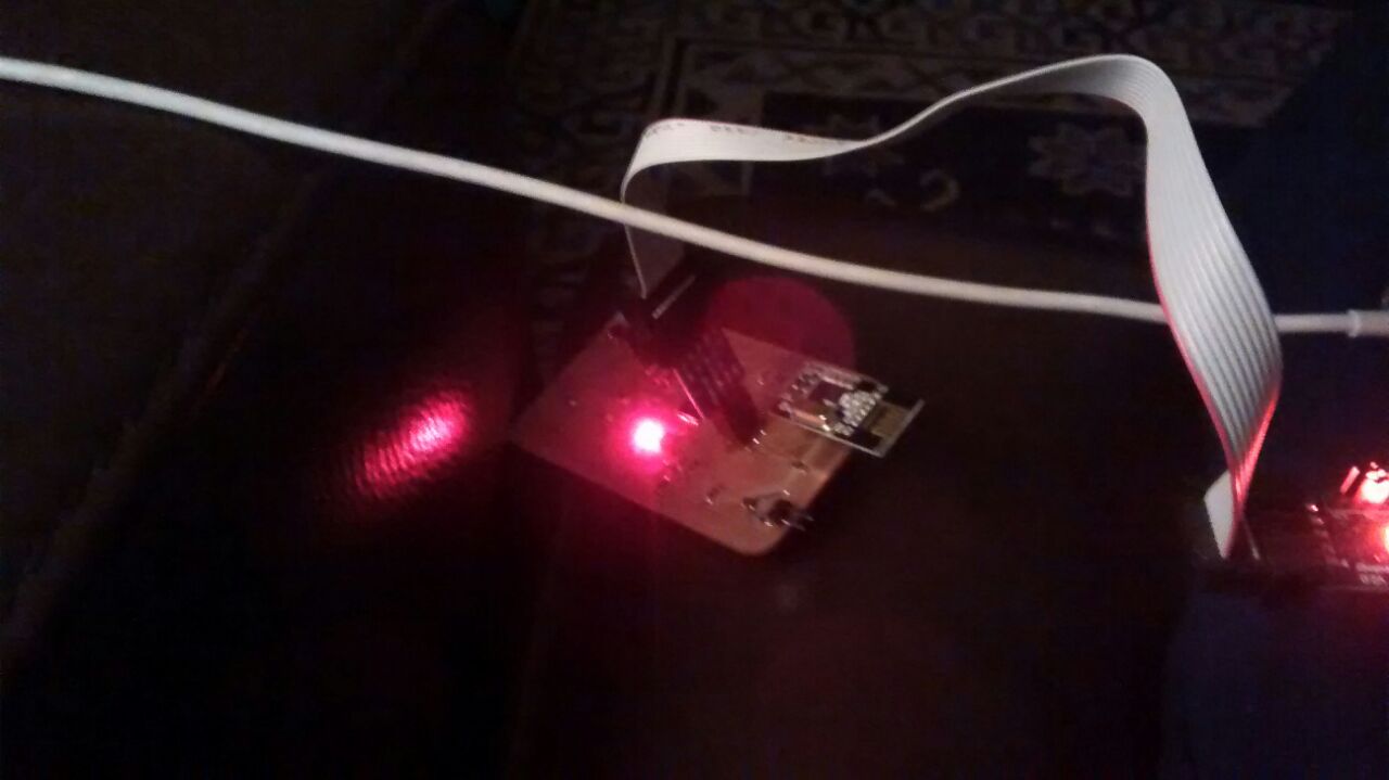
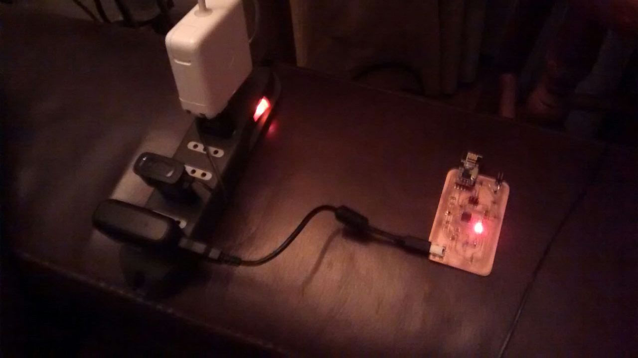
And voila! it blinks! although very slow (I'll blame the inner IC clock, since the compiled .hex must be setted up for an Arduino's 16MHhz clock). I also checked the boards powered from the USB cable, which led me to note that one of the boards blinks erratically, I checked the power and used an oscilloscope ... and re-soldered the IC's pin (the LED brightened stronger, but still weak) ... so it might be the SMD LED; I'll know on the next step when blinking with the LED panel connector.
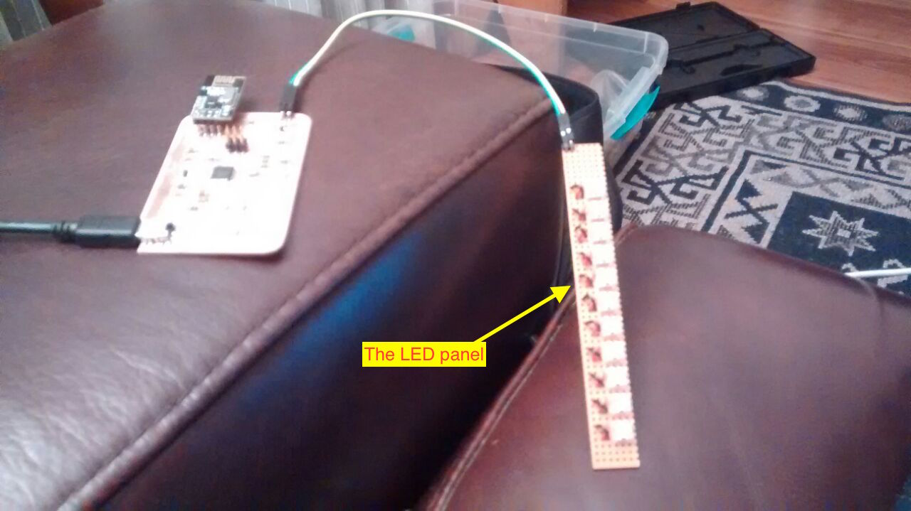
Check if I can turn on a LED trough the PCB-to-LEDs connectors (fully enable the MOSFET pin, no PWM yet).Check if I can make a blink to the LEDs panel ... at this point I would have at least a lamp!
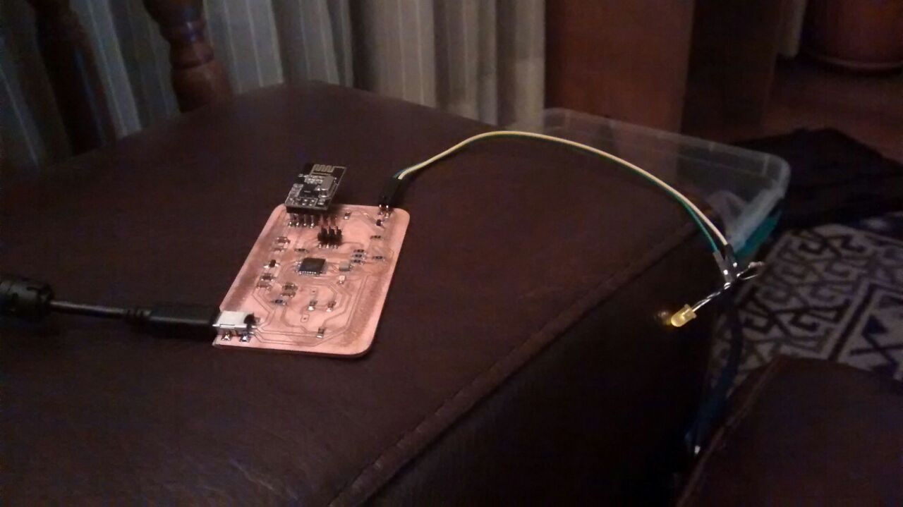
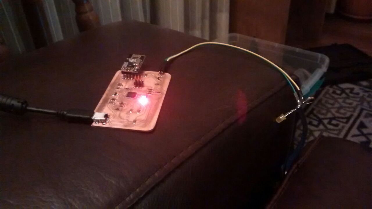
Again, accoding to the schematics the MOSFET/PWM pin is the PB2 pin, which correspond to the "Digital Pin 10 (PWM)" in Arduino. Following the steps done before (above) I have these sketch and .hex
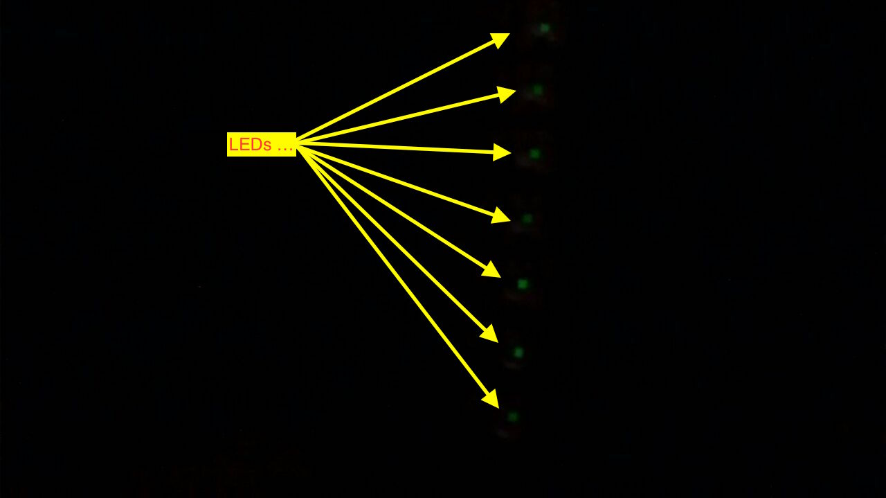
⋮And it worked! Although with the LED panel it barely illuminated (I verified the power source and it provides only 400mA, much less than the 2A power adapter I intend to use, so there's still hope).
Try to run/load the capacitive touchpad example code. Do a blink when the button is touched.
As I'm kind of in a hurry I went to the sure thing, the Arduino Capacitive Sensing Library with a very good explanation of how it workѕ (I want to re-code everything after on C!). NOTE that getting this examples to work might need to change the IC's fuses to work with the external 20Mhz clock (so far I'm still working with the internal 8Mhz clock); it might be wise to do this first on the erratic IC to verify communication afterwards with the programmer.
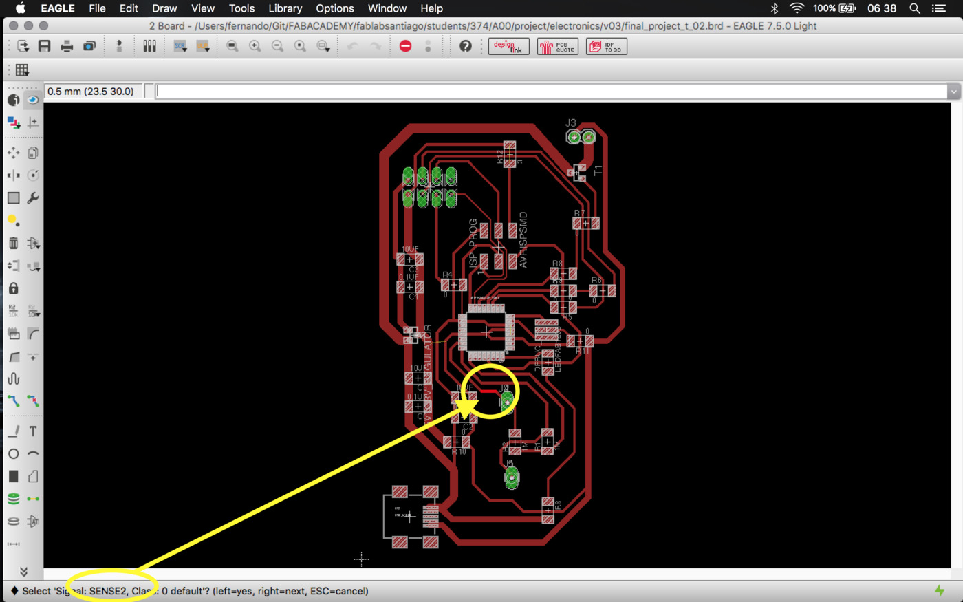
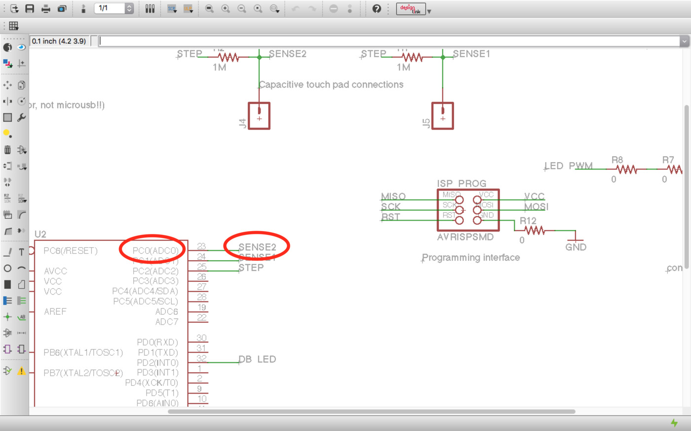
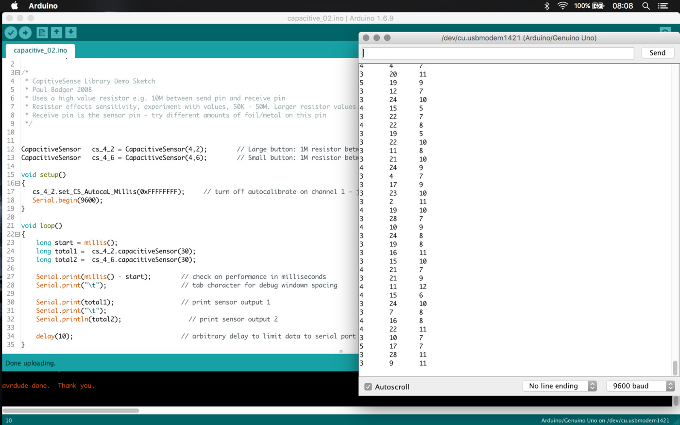
Here is the CapacitiveSensor.ino original example. And, as in the previous steps, the Pulse Pin is the PC2 (Analog 2 == Digital Pin 16) pin and the sensing pins are the PC1 (Analog 1 == Digital Pin 15, small button) and PC0 (Analog 0 == Digital Pin 14, large button). Here are the schematic , pin equivalence and the pin reference.
By studying the library's example and this Instructable I checked that I need to determine some response time values, so I'll execute the first example on an Arduino attaching my lamps touchpads and 1M resistors, as it is built in my PCB.
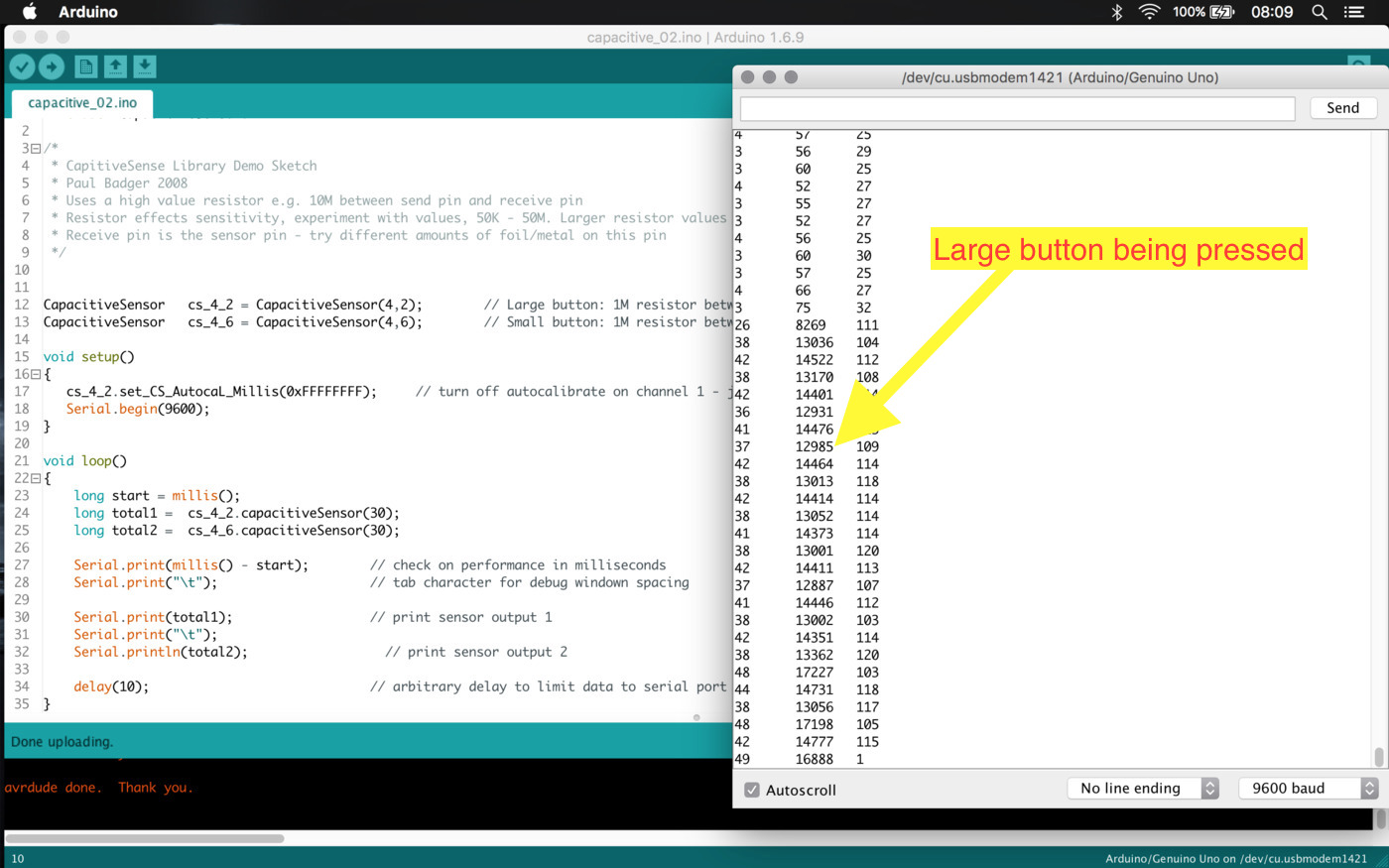
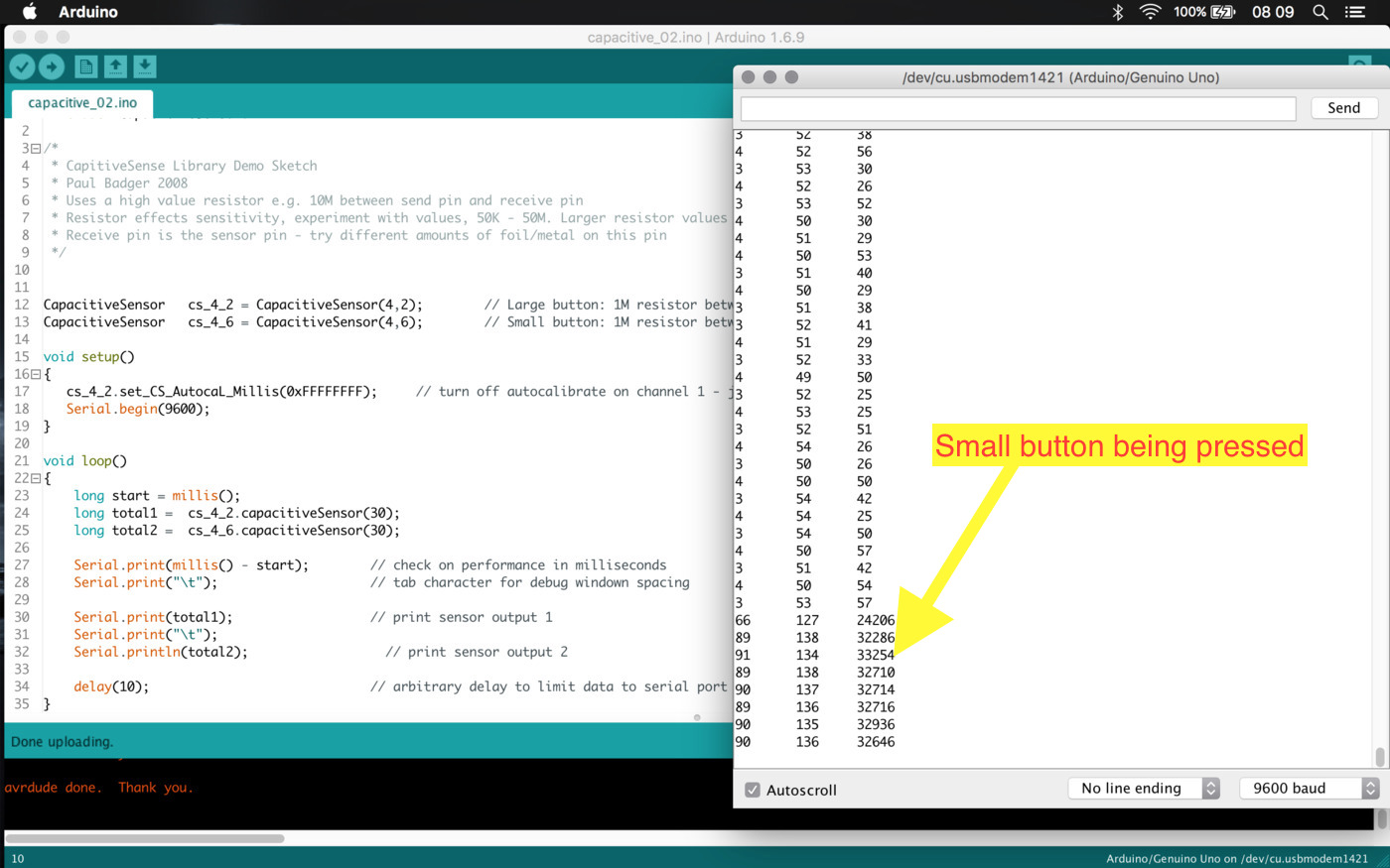
And I got a little victory ... the code works and I was able to measure the buttons with the same connections I have in my PCB
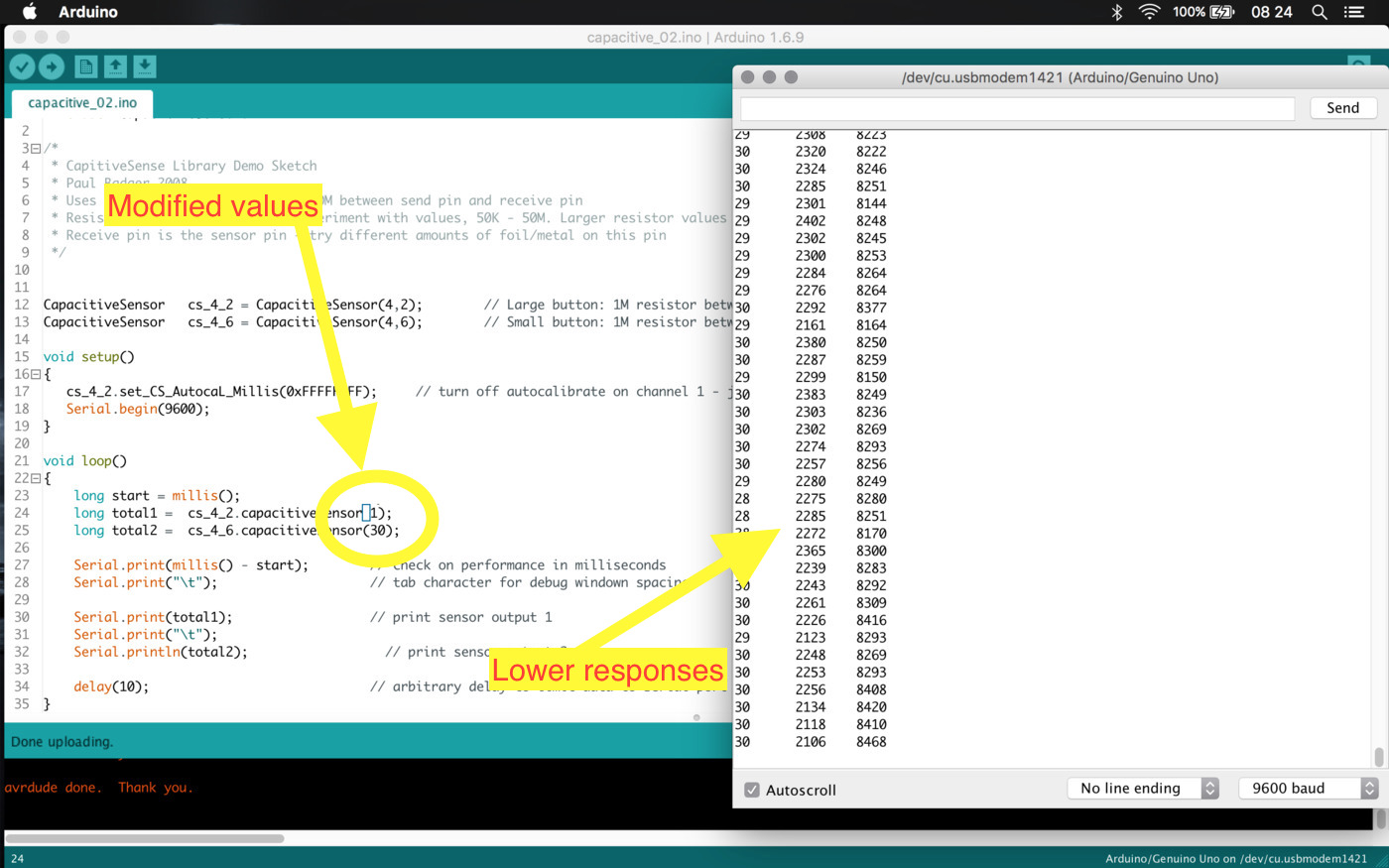
By changing a little bit values around I found that if I decrease the step pulse time I get a more responsive feedback (not sure), so I'll leave those values low. Here is the sketch.
So I made a simple blink using the touchpads and the LED on the pin 13 of the Arduino Uno using this sketch
Merge the code up to this point (accomplishment check-point)
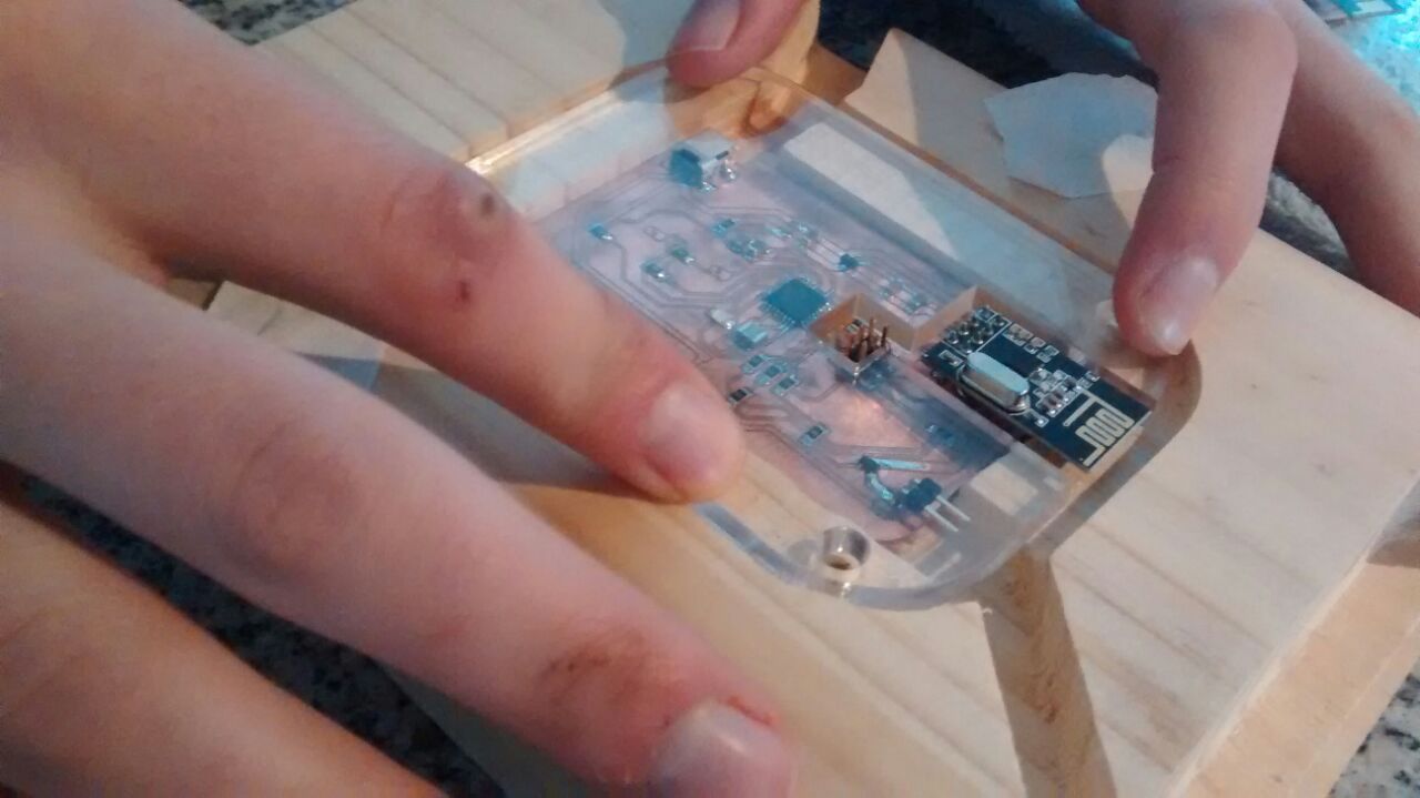
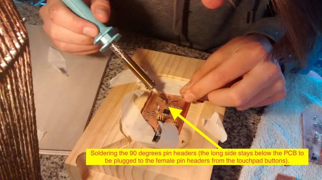
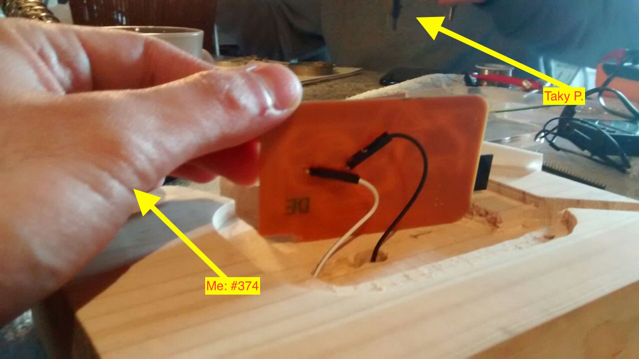
At this point I need the PCB connected to the touchpad buttons, luckily I got help to solder from my friend Taky Parvex ...
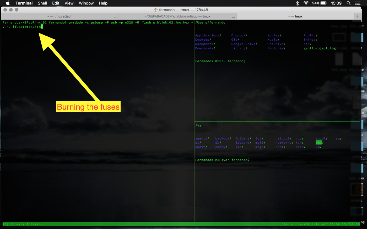
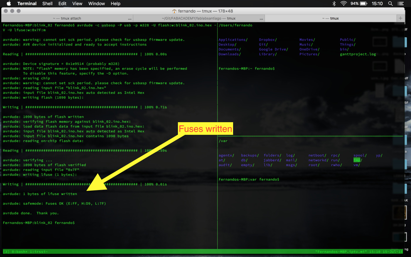
I'm also switching the fuses to use the external 20MHz resonator
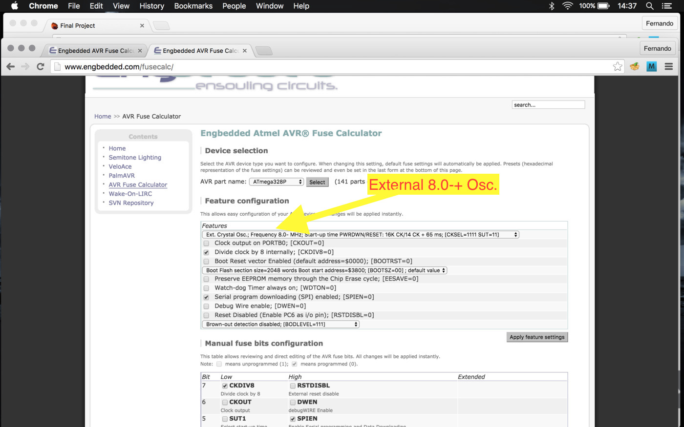
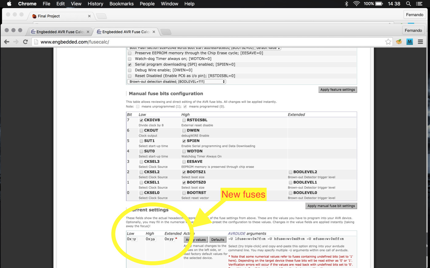
So the only fuse needed to be changed is the Lower Fuse, from 62 to 7F, which is done by running 'avrdude -c usbasp -P usb -p m328 -V -U lfuse:w:0x7F:m'
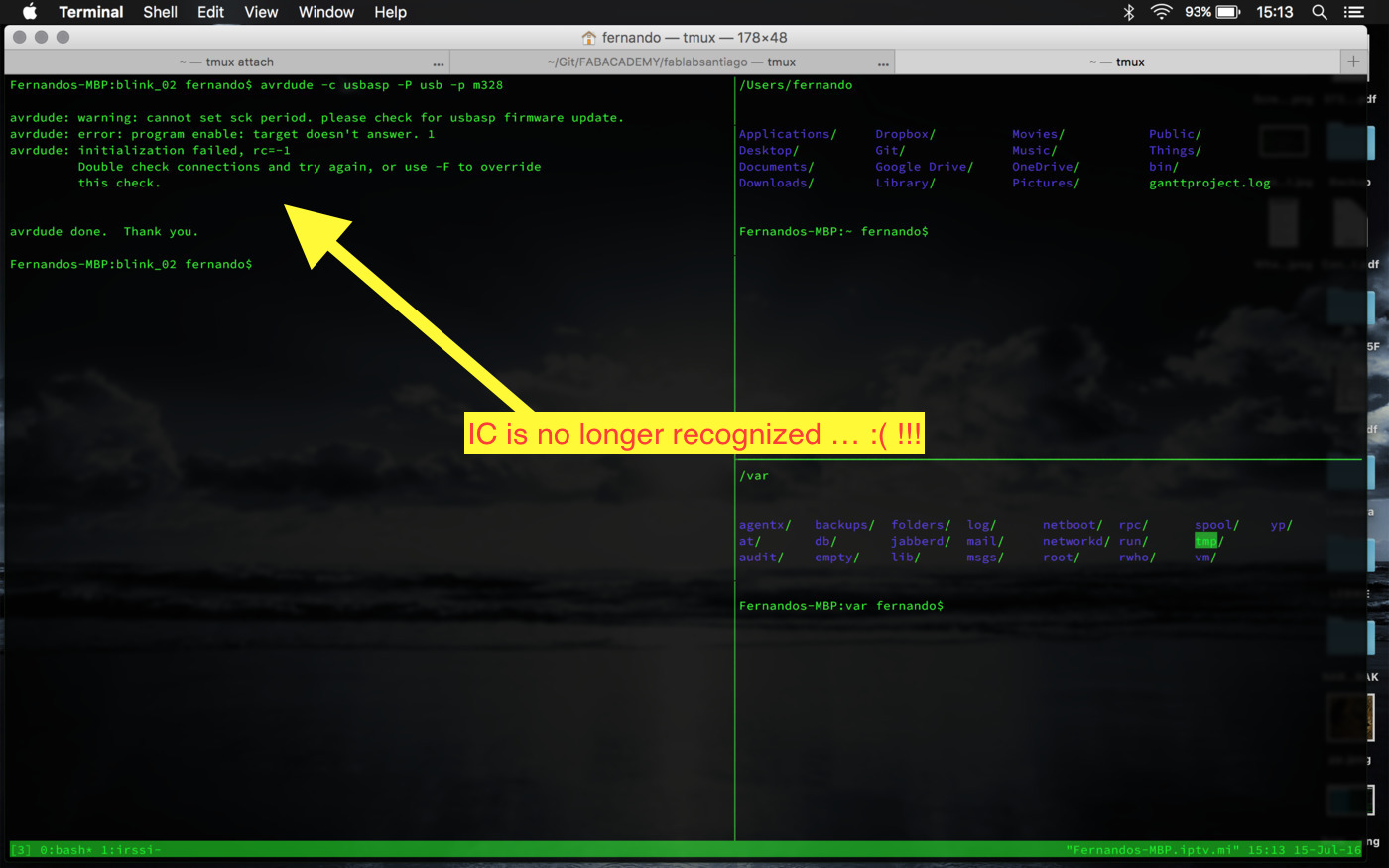
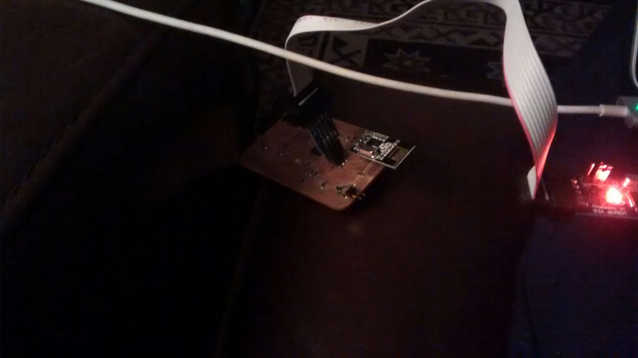
Catastrophe!!! One of the PCB is dead now and the other only works
when plugged to the ISP connector, although we were able to
un-solder the 1st and 2nd pin of the USB connector, the
malfunction persists when powering from USB (see
EXTRA_03 EXTRA_04 above).
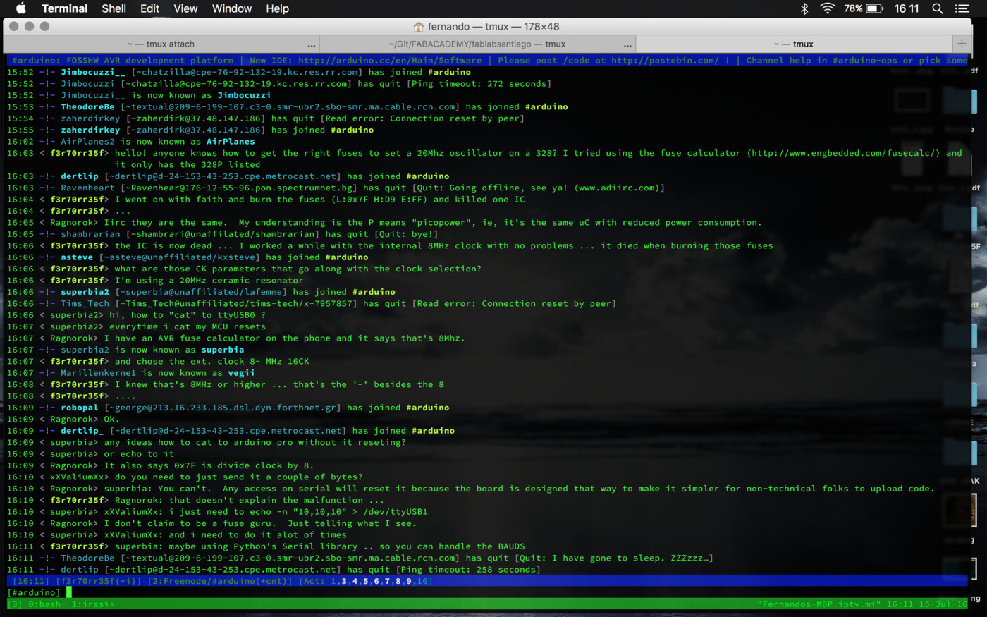
One of the possible issues when burning the fuses are those CK options on the Fuse Calculator. I might have mistaken there or maybe was the fact that there was no ATmega328 (not the 328P) on the list ... and according to the IRC dudes (#arduino on Freenode) the notation shouldn't be the problem ...
Taking in account all the (not so pleasant) events, it seems that
the only things left to do are 1. to make one lamp to light the bulb
with іts touchpad and ⒉. to take the hero shot.
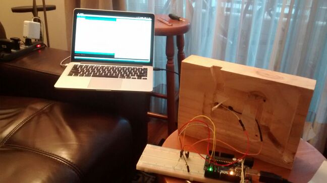
1. So here is the sketch and .hex files used. The result was that the LED got to blink during short time intervals according to the touchpad's actuation, but most of the time erratically ... and since I'm carrying both the powering and the clock issues from before ... I can't really explain now what's the problem ... at least it worked a while :)!!!
Now, to the datasheets!
- 8-Bit AVR Microcontroller with 2K/4K/8k Bytes In-System Programmable Flash (ATtiny24A, ATtiny 44A, ATtiny 84A)
- 8-bit AVR Instruction Set
Programming examples (links from the class)
Well, the first thing I made was to look was watching this video introducing the AVR programming toolchain. It suggest to read only the first datasheet's pages and then skip to the chapters, in which also you can only read their introduction and final part (that should give you an overall view of how to deal with each feature). It also introduces some of the logical bitwise operators that most people work with when working with ATmel chips at a register's level. It also recomends visiting the AVR Freaks forum's for more in-depth discussion.
Some interesting notes from the video:
To program your AVR chip using ISP you need to hook up 4 wires plus VCC and GND. Those 4 wires are:
- SCK (Serial Clock)
- MISO (Master input, Slave output)
- MOSI (Master output, Slave input)
- RESET (Tell the AVR to enter programming mode).
There are 2 groups of programmers:
DIY
- You can use an Arduino as ISP programmer
- You can use VUSBTiny as ISP programmer --> Minimalist
- You can use USBTiny and USBasp projects (DIY versions)
- Parallel port connector and 5 wires (DAPA) (?)
PRO
- AVRISP MkII (Atmel's own, very robust)
- LadyAda, Sparkfun --> they sell USBTiny kits
- Bus Pirate (SPI mode)
- USBasp-based designs available for 5$ from the far east
An example
Let's setup PWM on PB1 (OC1A) to run at around 1KHz with no CPU involvement. We need to configure three things:
- choose a Timer clock source
- set up PWM mode ("Fast PWMi, 10-bit mode")
- enable automatic output on PB1
To set 10-bit Fast PWM mode, we need to set bits WGM10, WGM11 and WGM12
So we could look up the bits in the registers, find out that WGM10 is bit zero and WGM11 is bit one, We then assign TCCr!A = 3; which is the sum of the two bits in binary.
Now we also need to enable output on PB, so we look up that bit: COM1AO,, which is bit number 6 ... to much binary manipulation
Bitwise manipulation
(1 << PB!):
- 1 in binary is 0b0000001
- << is the left shift operator
- Starting with 1, shifting over:
- 0b00000001 = ( 1 << 0 )
- 0b00000010 = ( 1 << 1 )
- 0b00000100 = ( 1 << 2 )
- 0b00001000 = ( 1 << 3 )
#include io.h at the top of the code includes the following definitions:
- #define PB0 0
- #define PB1 1
We want to turn on two LEds: PB1 and PB7
Bitwise or: |
- 0b00000010 = (1 << PB1)
- 0b10000000 = (1 << PB7)
- 0b10000010 = (1 << PB1) | (1 << PB7)
Bitwise XOR: ^
Bitwise NOT: ~
Bitwise AND: &
Summary:
Set bit with OR: PORTB |= (1 << PB1)
Toggle bit with XOR: PORTB =^ (1 << PB1)
Clear bit with AND and NOT: PORTB &= ~(1 << PB1)
We can set multiple bits:
TCCR1A |= ( (1 << WGM10) | (1 << WGM11) | (1 << COM1A1));
Shortcuts:#define BV(x) (1 << x)
#define setBit(P,B) (P |= BV(B))
#define clearBit( P,B) (P &= ~BV(B))
#define toggleBit((P