Assignment 16
Задание 16
In which I make a very expencive blinking diode
В котором я делаю очень дорогой мигающий диод
The only time it's legal to use Arduino
Единственный раз, когда можно легально использовать Ардуино
Networking and communications is something completely unknown to me so I had no idea about how would I manage to produce two or more devices (milling boards and soldering still takes me a huge amount of time) but then - thanks God and Ohad ( :D )- I found out that it's acceptale to connect two arduino devices. I thought that it will make this challenge half as easy but as always I was overestimating my abilities.
Создание сетей для меня - тёмный лес, так что мне было бы очень сложно сделать и задание, и два + устройства, но, слава Богу и Охаду ( :D ), я узнал, что в этом случае приемлемо использование ардуино. Я думал, что от этого задание будет раза в два легче, но, естествнно, я переоценил свои способности.

Wire library and master/slave relations
Библиотека Wire и связь "раб-хозяин"
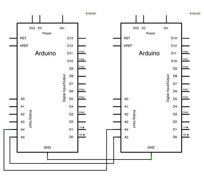
First tutorial I found on making networks with arduinos was making a I2C connections. Basically it's one master device which requests some data from its slaves from bus and it's possible to connect up to 127 devices in this network. On Arduino Uno to make this sort of connection is made using analog pins 4 and 5. Also, to make this easier, developers made a Wire library and some example codes.
В первом туториале по созданию сетей из ардуино, который я нашёл, речь шла про свзязь I2C. Если коротко, есть некое головное устройство, которое запрашивает данные со связанных с ним устройств при помощи единой шины, и такиим образом можно соединить до 127 устройств. На ардуино уно, которое я использовал, для этого используются аналоговые порты 4 и 5. Также, чтобы данной связью было проще пользоваться, была написана библиотека Wire и несколько программ, показывающих способности библиотеки.
Master device code. Original code by Nicholas Zambetti
  #include <Wire.h>

void setup() {
  Wire.begin();        // join i2c bus (address optional for master)
  Serial.begin(9600);  // start serial for output
  pinMode(13, OUTPUT);
}

void loop() {
  int i = 0;
  int d = 0;
  Wire.requestFrom(8, 1);    // request 1 byte from slave device #8

  while (Wire.available()) { // slave may send less than requested
   i = Wire.read(); // receive a byte number
    Serial.println(i);         // print the number
  }
  d = i*10; //
  digitalWrite(13, HIGH);
  delay(d); //light a diode and wait d*10 miliseconds
  digitalWrite(13, LOW); //turn off the diode and wait 1 second before asking again
  delay(1000);

}
Slave device code. Original code by Nicholas Zambetti
  #include <Wire.h>

void setup() {
  Wire.begin(8);                // join i2c bus with address #8
  Wire.onRequest(requestEvent); // register event
  pinMode(13, OUTPUT);
}

void loop() {
  delay(100);
}

// function that executes whenever data is requested by master
// this function is registered as an event, see setup()
void requestEvent() {
  byte i = random(100,255); //generate random byte number
  Wire.write(i); // respond with a 1 byte number
  Serial.println(i);
  // as expected by master
  digitalWrite(13, HIGH); //blink a diode to make sure
  delay(100); //that request was recieved
  digitalWrite(13, LOW);
}
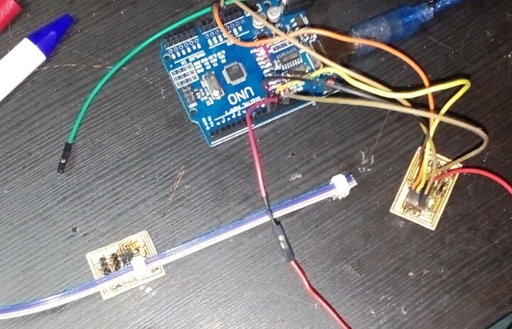
What happened: diode blinks at the same time as tx diode on master device but yet I didn't manage to make master diode blink with slave-generated frequency, I don't know why
Что мы видим: диод мигает одновременно с индикатором передачи данных на управляющем устройстве,

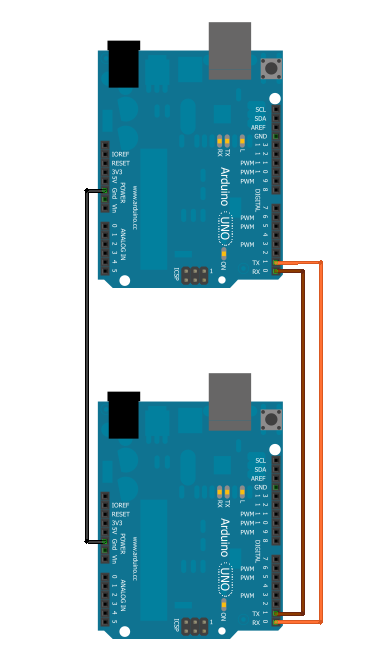
Serial connection and equality
Another way to communicate two devices is using UART (Universal Asynchronous Receiver-Transmitter). The main differences between two types of connections are: 1) here slave devices work on interrupts and that means that most of the time they are just minding their own business and react only if they are called 2) every device in network has its adress and ability both to send and recieve requests, thus, theoretically, every device can be a master.
Master device code. It's redesined blink code to transmit information through UART and fit slave's code
  void setup() {
Serial.begin(9600);
}
void loop() {
Serial.print('H');
delay(1000);
Serial.print('L');
delay(1000);
}
Slave device code. It's part of Physical Pixel example code
  const int ledPin = 13; // the pin that the LED is attached to
int incomingByte;      // a variable to read incoming serial data into

void setup() {
  // initialize serial communication:
  Serial.begin(9600);
  // initialize the LED pin as an output:
  pinMode(ledPin, OUTPUT);
}

void loop() {
  // see if there's incoming serial data:
  if (Serial.available() > 0) {
    // read the oldest byte in the serial buffer:
    incomingByte = Serial.read();
    // if it's a capital H (ASCII 72), turn on the LED:
    if (incomingByte == 'H') {
      digitalWrite(ledPin, HIGH);
    }
    // if it's an L (ASCII 76) turn off the LED:
    if (incomingByte == 'L') {
      digitalWrite(ledPin, LOW);
    }
  }
}
What happened: I made a complex and expencive blink. Yay?
Taking a step from Arduino
To step forward I had to make pcbs and program them to communicate with each other and with my computer. So, I took Neil's design of bus bridge and node pcbs and for node I downloaded Neil's firmware which reacts on recieving a command by blinking LED and as a firmware for bridge I wrote a code to switch states of LED.
Bridge code
#include
#define LED_PIN 0

//Serial mySerial;
const int tx = 4;
const int rx = 3;
  int input;
SoftwareSerial mySerial(rx,tx);
void setup(){
  pinMode(LED_PIN, OUTPUT);

  mySerial.begin(9600);
}

void loop() {

   input = mySerial.read();

  if(input != -1 ){

    switch(input){
      case 'f':

        mySerial.print("Off\n");
        digitalWrite(LED_PIN, HIGH);
        break;
      case 'o':
        mySerial.print("On\n");
        digitalWrite(LED_PIN, LOW);
        break;
    }
    mySerial.print("It's working! Wow! o/f to check it.\n");
  } else {
  }
}