Project:
Initial idea:
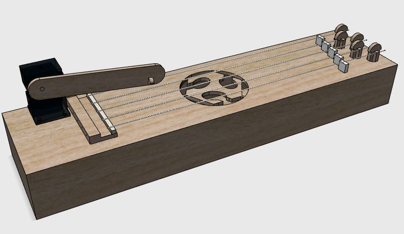
Plan C: Actually I am building an automatic Kantele, sort
of. Kantele is the national instrument of Finland. My 5-string
Kantele is automatically plucked with a mechanism built using
two servos. One servo plucks the strings and the other lifts the
pick so that strings can be skipped. A microcontroller controls
the servos according to the song to play. The default song is this.
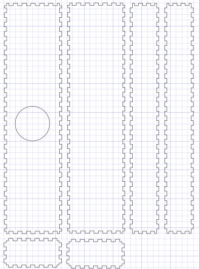
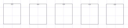
The body of the Kantele is built from laser cut plywood, and the
servo mechanism is 3D-printed. Below is a conceptual picture of
the body of the Kantele, with the strings missing.

Plan A: I am planning to build an automatic guitar tuning
machine. One part of the machine automatically plucks the
strings one by one, as the other part rotates the corresponding
tuner guided by the third part measuring the frequency of the
vibrating string. The construction of the machine requires
custom made 3D-printed and laser cut mechanics driven with step
motors. Pictures will follow...
Plan B: On the other hand, I also need a guitar to tune, so
maybe I'll build an electric guitar. The body, neck and
fretboard of the guitar are shaped with a 3d CNC wood router.
The microphones are wound using Juha-Pekka's Guitar
pickup coil winding machine. Laser cutter will be used for
cutting the various parts needed, such as the pickguard.
The 3D printer will be used for fabricating the accessories, if
possible.
Fabrication process:
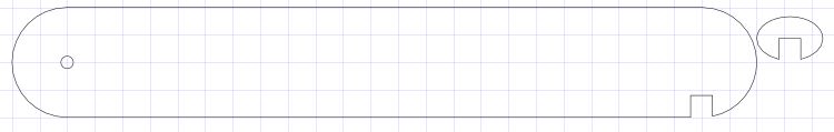
The sound box is made of 4 mm birch plywood laser cut with
tabs to fit the parts together. I designed the sound box with
Inkscape extension KM Laser Tabbed
Box Maker. The parts are glued with Titebond Original wood
glue. The holes for the tuners are reinforced and made longer
with a piece of 4 mm birch plywood with identical holes glued
inside the sound board, i.e. the top of the sound box. The sound
hole is a Fab Lab logo, naturally.
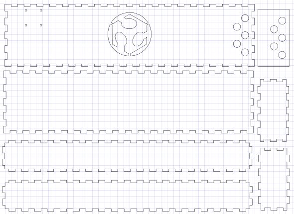
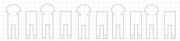
The tuners are also made of 4 mm birch plywood, designed with
Inkscape and laser cut. The two pieces form a tuning peg. The
tuners alone aren't really precise enough to actually tune the
instrument by adjusting the tension, and they are too small to
twist for the turning force needed. Therefore there are movable
nuts, which then determine the tuning of each string by changing
the length of the string. The nuts were laser cut from clear 4mm
acrylic.
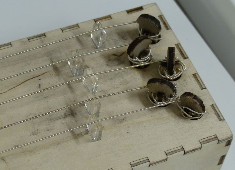
The bridge is laser cut from 4 mm birch plywood, and glued from
two pieces. The pieces have laser cut grooves for the strings.
When the pieces are glued together, the grooves form holes
through the bridge, but I had to clear the holes with a small
drill bit. The strings are tied the same way as in a classical
guitar. There is also a laser cut groove to hold the saddle
laser cut from clear 4 mm acrylic.


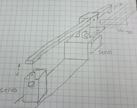
The servos have 3D-printed housing. The housing of the lower
servo, the one moving the arm above the desired string, is
attached to the top of the instrument with screws. The housing of the upper
servo is attached to the axis of the lower servo with a screw
going through the housing of the upper servo. The upper Servo
holder has connecting pins to attach it to the plate that came
with the servo. The original sketch for connecting the servos
was much too complicated and flimsy.
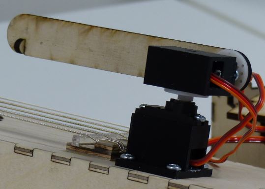


The arm playing the strings is laser cut from 4 mm birch
plywood. The upper servo moves the arm up and down so that the
strings are played by tapping them, instead of picking, like one
would normally do when playing an ordinary Kantele. I tried the
picking method, but soon realised, that I probably don't have
enough time to make it work by finding the correct flexibility
for the pick and arm. However, I am pleased with the current
sound of the instrument, so I'll stick with the tapping method.
It looks something like this when everything is put together. I
found a 3D model for the servo from here: http://www.123dapp.com/123D_Design/Servo-Radio-Shack-2730765/3195924#
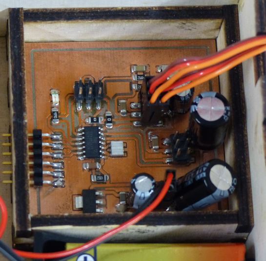
Control electronics:
The control electronics uses the PCB made for the output devices week. I connected
all four outputs labelled PWM to 3-pin connectors to be on the
safe side. I ended up using the outputs related to the
Timer/Counter1 of ATtiny44A. Neil's
example code for hardware pwm was a perfect starting
point. I needed two hardware PWM outputs for Timer/Counter1,
i.e. outputs PA5 and PA6. Neil's example code had only one PWM
output, but a modification to TCCR1A solved the problem, with
the help from Jani of course! The complete datasheet for the
ATtinys is a handful, and finding and understanding what one
needs can really be a lot of work:
TCCR1A = (1 << COM1A1) | ((1 << COM1B1)); // clear
OC1A and OC1B on compare match, | ((1 << COM1B1) was added here
Otherwise I just had to adjust the correct
values for OCR1A and OCR1B registers to move the arm on
correct string and to tap the string to play the instrument.
The current version can play two songs: "Vaka Vanha Wäinämöinen
(Steady old Wainamoinen)" is an old Finnish folk song from the
Kalevala, the national epic of Finland, traditionally played on
Kantele. The other song I composed myself, sort of. One can
change the song by pressing the SONG button before the song
begins and hold the button until the song begins. The state of
the button is polled before playing a song.
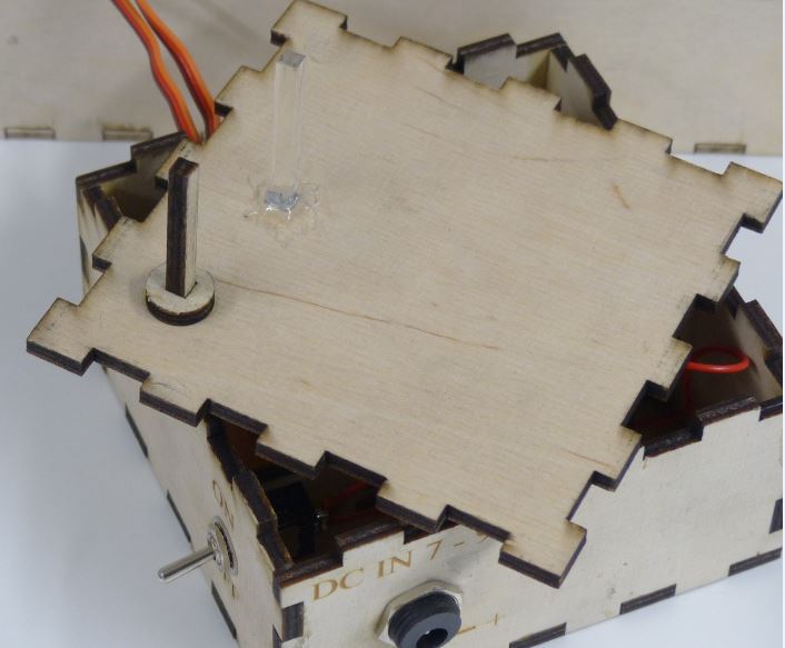
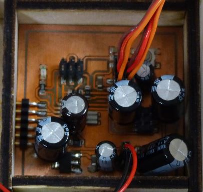
The electronics is installed in a laser cut 4 mm birch plywood
box. As the LED and push button are in the PCB in the bottom of
the box, a light conductor made of clear 4 mm acrylic brings the
light to the top of the box. The light conductor is hot glued to
the top of the electronics box. The push button is reached with
an extension arm made of 4 mm plywood. The 4 by 4 mm stick is
glued with the other round plate to make the button. The other
plate is glued to the inside of the top of the electronics box
to guide the extension arm on top of the push button. The LED
blinks in time with the song. The PCB is installed in a frame
made of 4 mm plywood.


The power comes either from a 9 V battery or from an external
7.5 - 9 V DC power supply. When then plug of the external power
is connected the 9 V battery is disconnected by the power jack.

Final Instrument:
I installed old classical guitar strings which I cut in
half. I use two low E strings and one A string. Having strings
with the same width works, because the tuning is in d minor
(d–e–f–g–a), so that the differences between the frequencies is
small. I tuned the strings and started testing.

Testing:
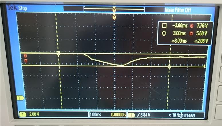
The initial tests with the servos showed occasional erratic
movements. I suspected the reason to be too small power supply
bypass capacitors. So, I installed 100 uF capacitors on both
sides of the voltage regulator. The erratic movements almost
disappeared. Now that it almost now worked, I decided to measure
the voltages. In the worst case the regulator input voltage
drops from 7.5 V to 5.7 V, and the 5 V output drops to 2.9 V.
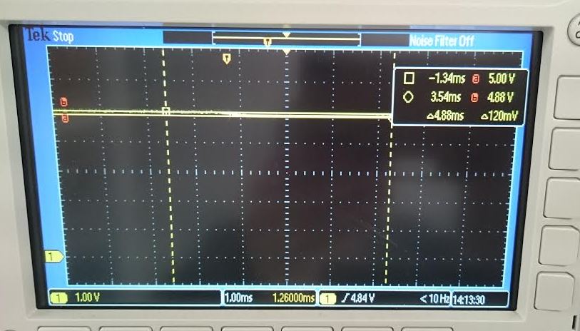
I added more
capacitance, this time 1000 uF on both sides of the
regulator. Now the input drops to 6.7 V and output to 3.9 V.
Even more capacitance is needed, but this seems to work now.
Update: I added 2 x 1000 uF and 220 uF to the +5 V power
rail. Now the +5 V voltage drops to 4.88 V with 3320 uF
capacitance. Problem solved.
Regulator voltage drop with 100 uF capacitors:

Regulator voltage drop with
1100 uF capacitors:


Making of the Video:
The servos are rather loud. So, for the video I made a
cardboard box to hold a microphone under the instrument to catch
more the actual sound of the instrument, but not the sound of
the servos.
I recorded the video in Full HD with my compact camera,
compressed the video bitrate to 1500 kbps with Handbrake, which
also added the subtitles I made in SRT-format. Then to make
sure, that the video is playable in browsers, I used avconv with
the following parameters
provided by Neil:
HTML5 MP4 encoding
variable bit rate 1080p MP3:
avconv -i input_video -vcodec libx264 -crf 25
-preset medium -vf scale=-1:1080 -acodec libmp3lame -q:a 4 -ar
48000 -ac 2 output_video.mp4

Problems and solutions:
- It took a while to understand that the initial servo mechanism
was too complicated and flimsy. Bolting the servos together in
90 degree angle is simple and solid.
- I had many complex ideas for the tuners, most of them
borrowing from guitars, but a simple tuning peg in a hole does
the trick, with movable nut of course.
- The initial idea was to pick the strings sidewards, but it
turned out to be too time consuming to succeed. I happened to
tap the strings with a pencil and got a decent sound, which was
even better when done with a servo.
- The behavior of the servos was erratic in the first tests. A
lot of capacitance had to be added to keep the power supply
stable.
- The servos are too loud, probably because of the internal
gears. However, now that I know, that I can get a decent sound
by tapping the strings, why not replace the servos with
solenoids, one for each string. The vertical movement is easy
the accomplish with a simple solenoid. The solenoids can even be
made inhouse with Juha's
Guitar pickup coil winding machine.
Bill of materials:
-
0.15 m2 4 mm birch plywood, 12 €/m² = 1,8 €
- Titebond Original glue < 1 €
- recycled classical guitar strings 0 €
- 3D printed parts 100 cm3 PLA ~ 3 €
- HobbyKing servo HK939MG 5 € * 2 = 10 €
- recycled 7.2 - 7.4 V battery 0 €
- microcontroller board:
- ATtiny44A 1.3 €
- 20 MHz resonator 0.53 €
- 5 V regulator 0,92 € €€
- 51 * 51 mm PCB 1,3 € (127.0mm x 76.2mm
4,93 €)
- resistors, capacitors, connectors, switch 2 €
- total ~ 20 €
Source files:
Initial design:
Kantele 123D Design
Kantele Inkscape
Final product:
Kantele Box
Tuners
Nuts
Bridge
Saddle
Lower Servo
Holder
Upper
Servo Holder
Pick arm
Electronics box
PCB box
LED Light Guide
Push Button Extension
PCB eagle
schema
PCB eagle
layout
PCB_traces
PCB_outline
Presentation
video
Presentation
slide
Home
-

This work is licensed under a Creative
Commons Attribution-NonCommercial-ShareAlike 4.0 International
License.