We started thinking about what we could possibly make; should it be two or three axis, what should it do, what do we need in the lab, could we make something useful?
A couple of our initial ideas:
- chocolate printing
- electronic circuit painting
- ceramic 3D printer
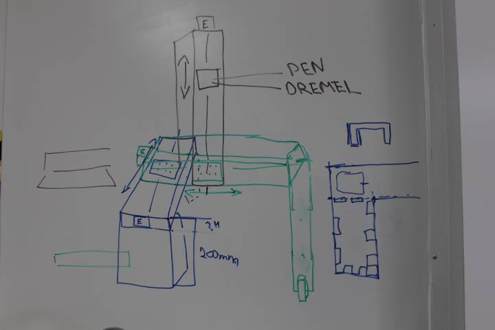
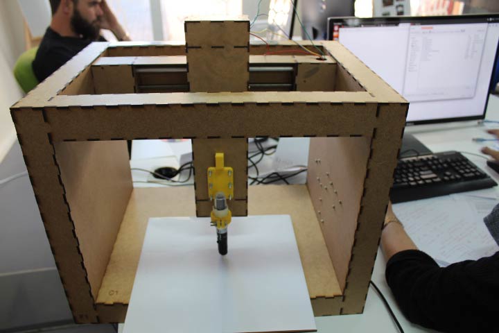
Eventually we settled on doing a 3 axis dremel or drawing tool.
MACHINE HOUSING
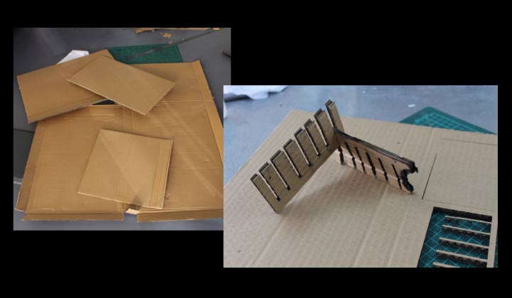
I (Monica) started by using 5mm cardboard (all we can get our dirty hands on here in Namibia). I had to cut all the cardboard to size to ensure that we could get two arms out of the materials we had. I had some spare so I used that to do a test comb for the fitting that the parametric resize. I worked around the 5mm size and found the best size which was the 5mm exactly, so as not to bend and warp the fits too much. My first firey experience with the laser cutter.
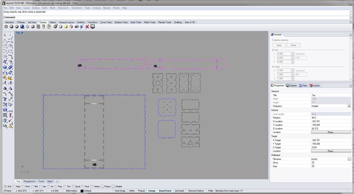
I downloaded and used the Grasshopper plugin for Rhino, this was my first experience actually using the software, so that I could take advantage of the parametric design files for the parametric stage from the MTM site. It was quite a task to understand all the parts I needed to change to ensure the 3mm files updated and adjusted according to the much thicker 5mm cardboard we had. I saw changes in sizes all around the files, and so assumed the best.
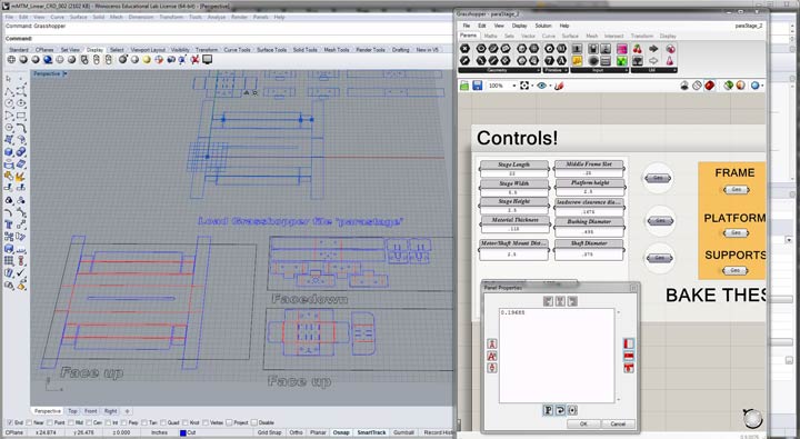
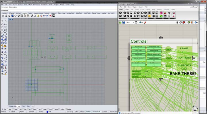
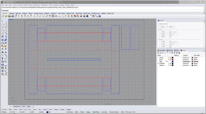
I did note that a lot of the holes and edges were not exactly in the right places in the files provided so made some minor adjustments and additions to the files. I also had to shorten the fold over arms of the machine to fit the cardboard size, which I was planning on attaching as support once the arm was built. Once ready I exported as DXF to corel draw to cut on the laser cutter.
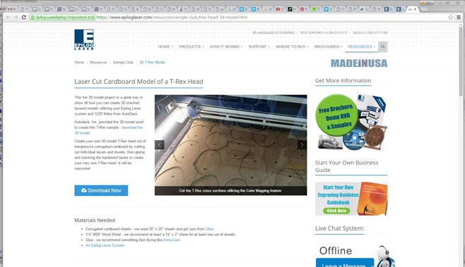
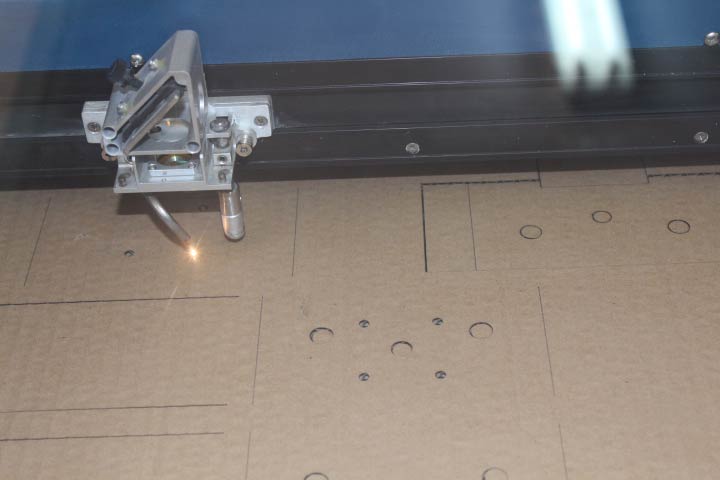
I set up the laser cutter, following instructions from the epilog site, as our cardboard was thicker and our machine not the exact same power, which was quite daunting due to fear of fire (which I experienced with the comb fitting) and breaking precious laser parts and wasting what we had in cardboard. The t-rex example used similar material and the same watt machine. The settings I used were:
Combined Vector and Raster,
using the Floyd Steinberg Image dithering setting.
Vector Cutting (outlines in blue)
15 speed
100 power
100 frequency
Raster Engraving (fold lines in red)
100 speed
20 power
100 frequency
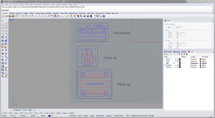
I used the side ruler clamps of the laser cutter to hold the material flat. I had a few fire flares in places where the cardboard had been folded previously, but I manged to get at least one arm out. I did learn later that taping the cardboard can reduce fire flare ups.
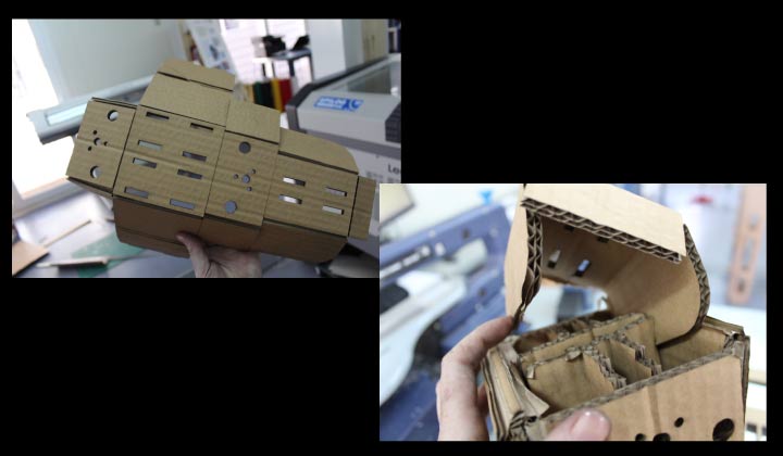
I thought I had managed it but once I started assembling the arm I soon realised that the parametric was not suitably adjusted and that when folding the parts over each other it became impossible to assemble or fit the rods through the holes. The material was just too thick, blocking holes and becoming to too thick to fit together. I used pins to attempt to keep it together at first.
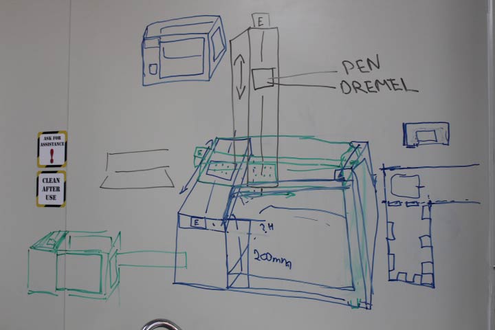
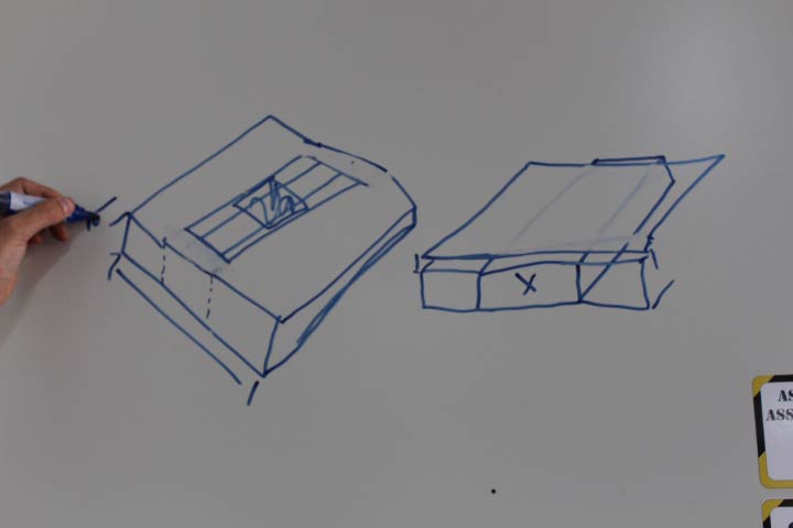
We wanted it to have a good finished look and sturdy structure as the dremel would undoubtedly cause a lot of shaking, luckily we have a lot of 3mm chipboard in the lab and decided to use that instead. I started looking at how the machine would run and looked at a few ideas online. Bjorn and I started drawing out base ideas and sizes. The motors had also just arrived so that helped the planning quite a bit as I had to adjust quite a few holes for the motors and wiring, as per our planning, and being able to measure the exact sizes helped a lot!
I had the test comb from the snap fit excersice week 3, so I knew what to set the sizes too. I also found this link, on the fablab Puebla site for a machine built with 3mm chipboard which I imported into Rhino. This helped as I used the fit as a key for all my artwork.
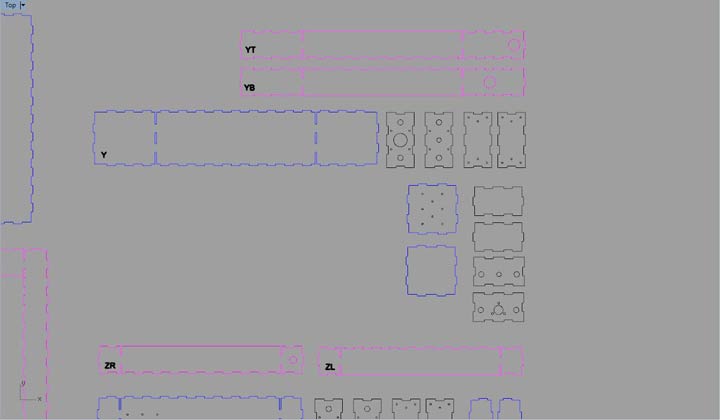
So I started with the arms and made them symetric, they weren't in the downloaded file, I felt this would be useful later on, which it proved to be. I set up the file to be interchangeable no matter which arm we were using, you can simply turn the "lid" on the top of the moving part to fit to wether the arm would be running up or across.
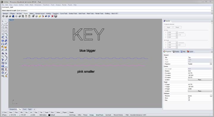
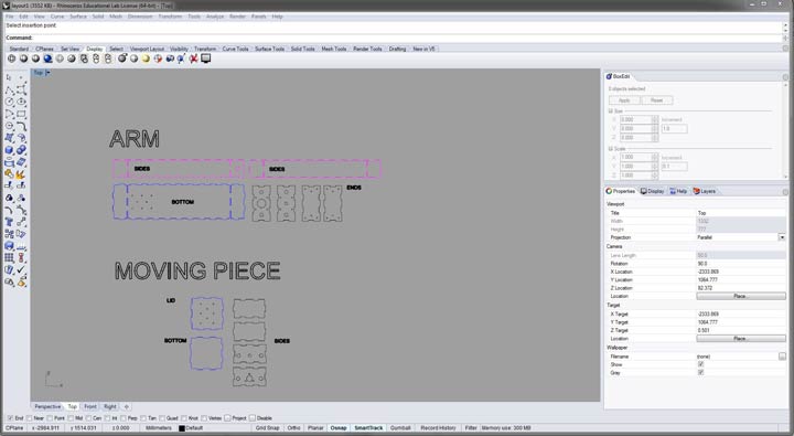
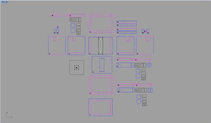
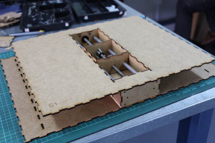
I then moved onto making the shell. We had had quite a few ideas about running the x axis on one side with a wheel but realised that we could simply build a box around and have it sit quite stably in the centre, this allowed for the base of the x-axis to become a complete part of the bottom of the machine. rather than slotting it in, I designed it to snap fit together. This also saved some chip board.
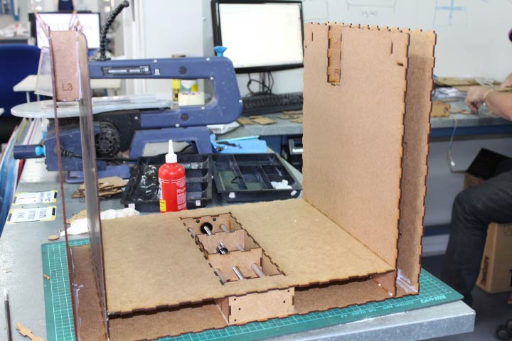
I realised we would need inner structures to hold up the y axis and so I built them into the sides of the box, this provided an opportunity to build in stability and a housing area for the motors as there were now to outer covers. I built in a door for the eletronics which Bjorn eventually fastened onto the inner wall of the machine and hinged on the cut out for a door. I set up the electronics door and area for the right, for the wiring to run to the electronic boards. I built a top for the x axis to snap fit to the inner wall and onto the top of the arm, so I had to flatten the teeth on the outer sections of the arm, and then rather than the "lid" on the moving part I built a snap fit bed. As I had done this I flattened the teeth on the y and z axis for aesthetic reasons. I also built in covers for the motor and end area of the arms.
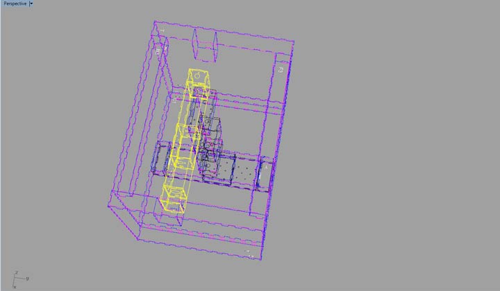
Once all this was completed however I saw that the y axis would not possibly fit the width of the box, and luckily as I had made all the fits symetric I was able to easily adjust the length of the arm to fit the width of the box. I also added holes to the y axis arm for the z axis wiring to run through, to the inner section it would sit on, where I also added a hole for it to run directly into the box.
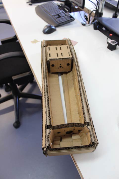
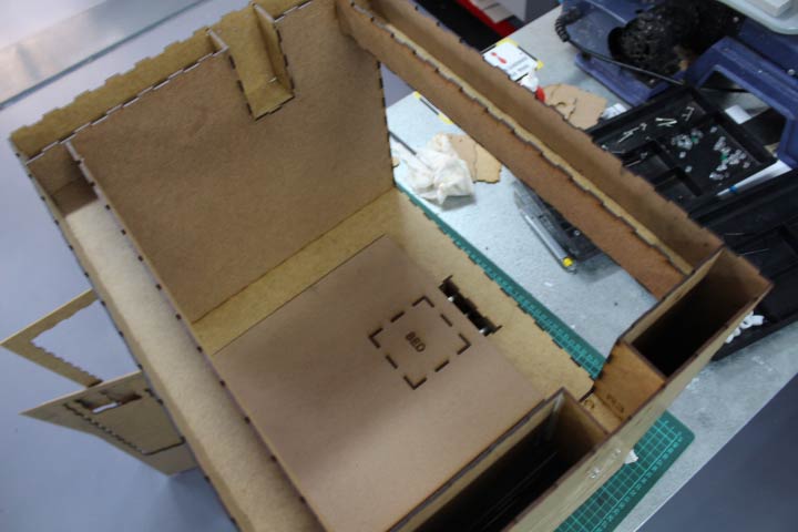
Once it was all cut and we started assembling we realised that the moving boxes needed some space at the bottom to not run exactly on the bottom of the arm as we would be adding screws, so I lifted the boxes by 1 mm except for the z axis box which needed to be lifted almost 4mm to clear the screw heads. I also needed to recut the bed, as we had not taken into account that the x axis would be the main moving part, so I moved the snap fit back so that the work area was increased. Once that was finalised we put the machine together, it is very sturdy, but we still wood glued edges for extra strength.
DOWNLOAD MACHINE DESIGN FILES HERE
MAKE THE WIRES
My work (Bjorn) was to help with the design of the machine and the manufacturing/wiring of the Fabnet and the Gestalt modules. The information for the Fabnet can be found here.
My plan was to try and find as much research/information as possible to ensure that the machine is wired correctly and with the right voltage to not burn out the gestalt nodes.</
Below is a list of websites I followed to get this right
- http://fabacademy.org/archives/2015/as/students/huang.yi-pin/15.html
- http://fabacademy.org/archives/2015/doc/MachineMakingNotes.html
I then looked around the lab to see what old stuff (recycled from old Laptop etc.) I could find to use for the power , the list below is what I came across.</
- http://www.communica.co.za/Catalog/Details/P0798026981
- http://www.communica.co.za/Catalog/Details/P3264423910
So the first thing I did was to mill out the Fabnet and solder it.
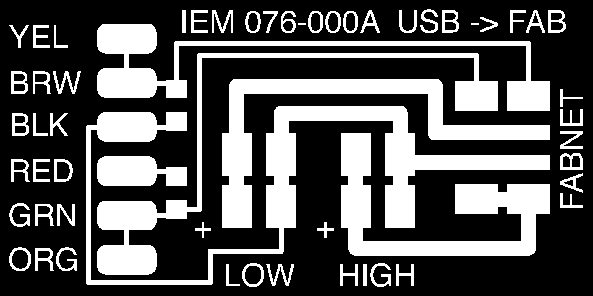

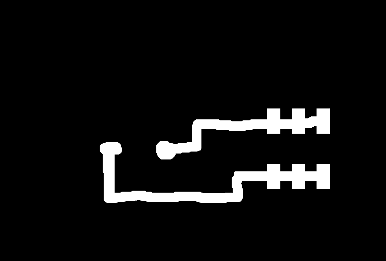
After allot of research and trying to find the best illustration for the wiring I came across this. I followed this Picture and replicated the wiring exactly the same way with the colours to not get confused with a rats nest of wires.
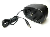
This is a DC Power plug that we had lying around

Gets connected with this, Power 220V AC to 12V DC.
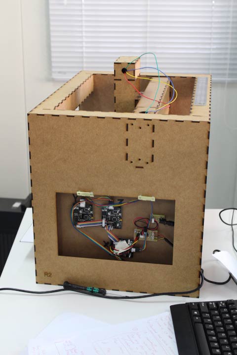
I made a little circuit board to solder the plug to so that the cables look neat and easily understandable.
Final outcome
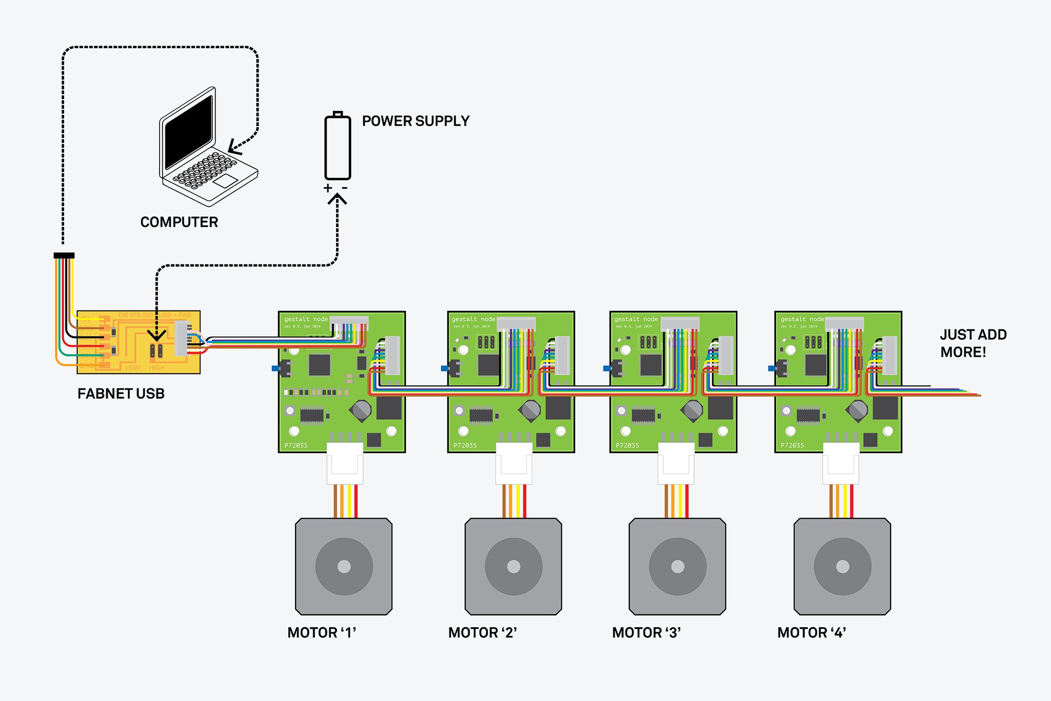
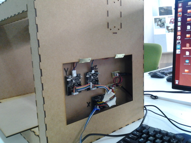
Wires from the Fabnet to the first gestalt node

overview of all the wires, sum of the nodes needed extensions as the node wires were not long enough.
MAKE THE MACHINE COME ALIVE!
Finally, the machine was assembled and ready to take the next step, to become alive! This was my (Kirstin's) task and, as I have been having some problems with the coding from the beginning due to being a novice, this was daunting to say the least.
The plan of action to get this to work was as follows;
- follow the tutorial step-by-step
- read at least two other student's pages before doing ANYTHING
- Action the tutorial and make the machine draw
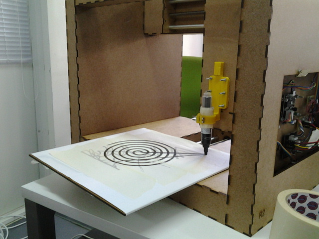
Eventually we settled on doing a 3 axis dremel or drawing tool.
THIS IS THE STORY OF THE MACHINE THAT CAN DRAW (and will also engrave using a dremel instead of a pen/paintbrush)
I read many many many student pages and found a few stand-out issues from the get-go. Many students seemed to be having issues with the Gestalt Nodes and this seemed to be because some people refused the nodes, whereas others had in fact just plugged them in and started the tutorial process. I decided NOT to refuse or unfuse or remake or unmake the Nodes. The first thing then was to install all of the dependencies. I downloaded MANY different Gestalt zip folders but in the end I use the wxGestalt folder. This is the tutorial here.
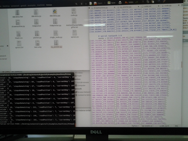
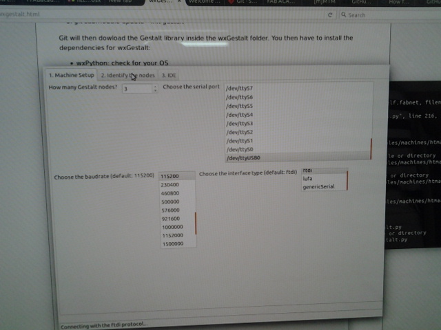
The computer I used was LINUX and runningon UBUNTU 14.04. You have to navigate to the right folder when you are ready to test the machine and this was a really lengthy process because there are a range of folders in the wxGestalt folder. Once navigating there, you need to ensure to open the file you are running (depends on the example that you pick) and check the line specifying the port that you are running, in my case it was USB0. Then in the terminal, navigate back out to just /Desktop/wxGestalt and run the line python wxgestalt.py and this will open up the machine GUI. In the GUI I selected the USB0 for the port, and left the standard settings for FTDI and 115200 baudrate. Initially we had 3 Nodes but one has no light flashing when powered and we had a power up the day before where the Node in question became REALLY hot, therefore we think we may have fried the board. I also did some research with Monica and we found that Nadya had relayed to another student with a similar problem (this was in the email stream) that the serialcommunication may be fried! But we will not give up here - we modified the machine to become a 2-Axis machine and will have to check the Node and see if w can mend it.
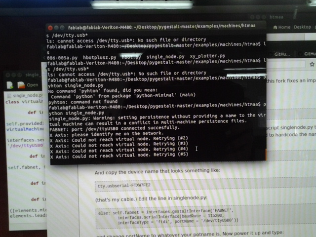
Now that Bjorn and I had modified the Nodes to make y=x and z=y we reset the Nodes in the GUI from 3 to 2 and reidentified the Nodes. I then saved a new machine and if you navigate to the HTMAA folder inside the wxGestalt folder you find a test.vmp file. REALLY IMPORTANT = if you want to reset the Node axis then you MUST delete this automatically generated file, if you don't then you will either get error messages or the machine will stay in accordance to the previous settings. I ran the xy_plotter.py example code (In the terminal type python xy_plotter.py) and everything worked well (remember to change the port to the /dev you are using or you will get errors in the terminal. The code running in the terminal first checks if the usb port is connected, and once this is checked it asks you to identify the nodes for each axis (this is done in the testing phase of running the various .py files i.e in my case xy_plotter) and you push the buttons on the node you want to be x and y. They are then identified and the terminal runs the example coordinates of the files. HOORAH! IT WORKED!