 JOSE REAL
Week 13 - Output Device
This week we make a input board adding to it an output device.
First tests
To start i had one hellostepperbipolar board milled from Fab Academy.
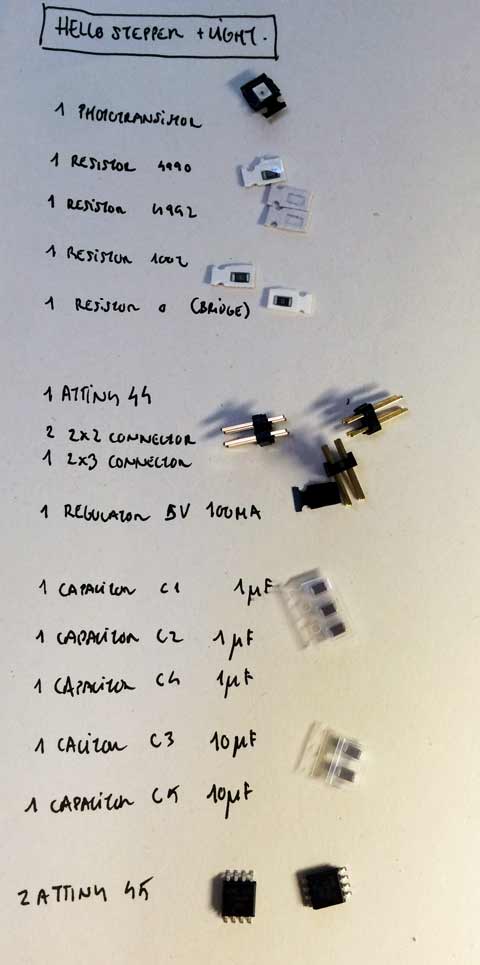
There are the components:

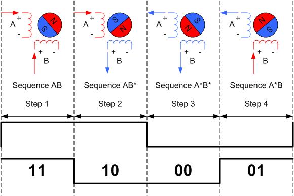
I have used a Nema 17 bipolar motor. This is an scheme of how a bipolar motor runs.

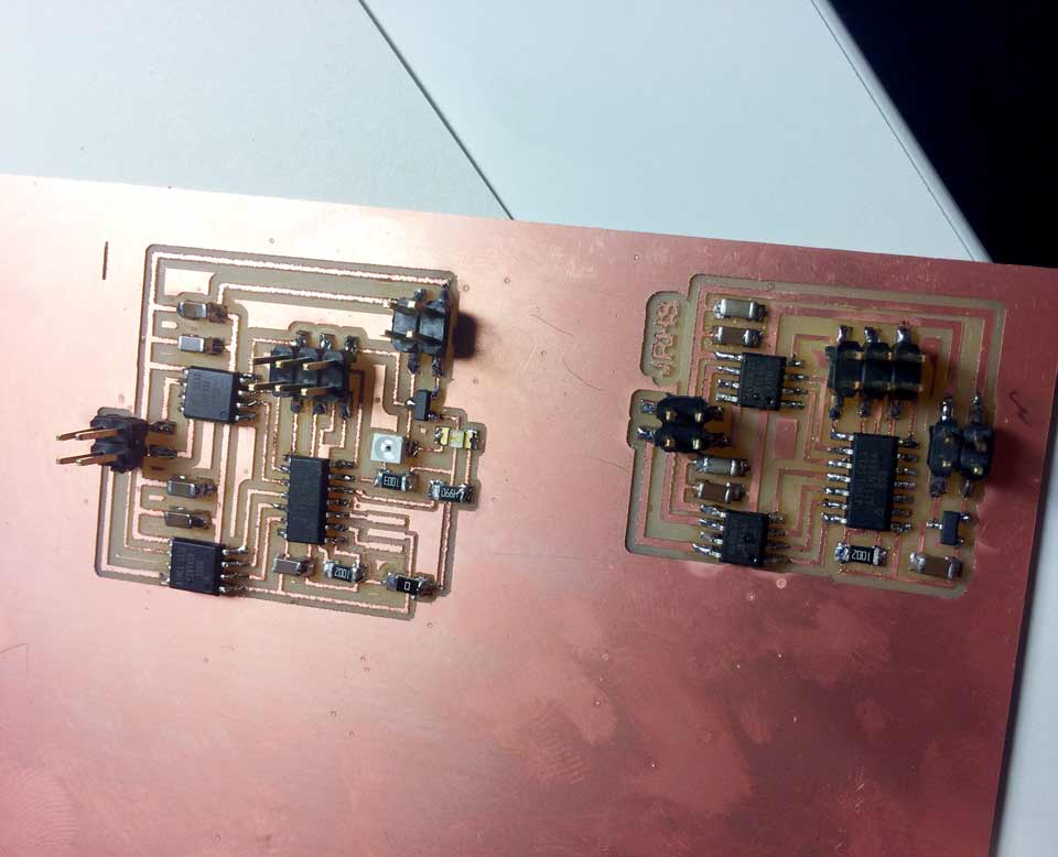
First I milled a hellostepper board and a hellostepper board with a LED and a light sensor. I did both at once but I could not cut with the milling machine so I used a guillotine with not very optimal results.
I've gotten it to work the but I could not save it in a video.
Something was wrong because one of the H bridge stopped working. I replaced it with a new one did not work so I decided to work with the first hello light board.
I want to replicate this one to learn about it.
A peculiarity with this board was that used two ATtiny45 instead of an H-Bridge. Still I decided to make it such. Once welded and programmed didn't work. I found the design in Eagle was wrong as several tracks, which probably led to short out the micro joined.
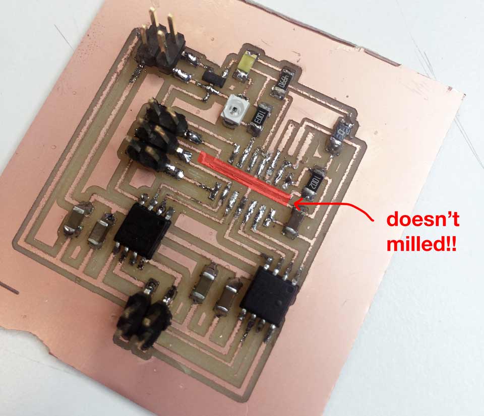
I decided to start again...
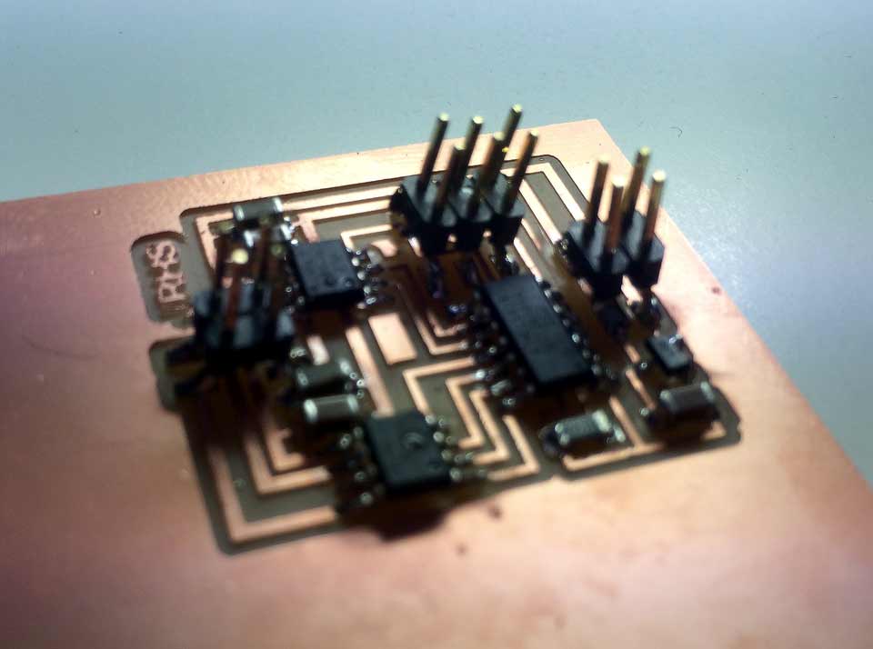
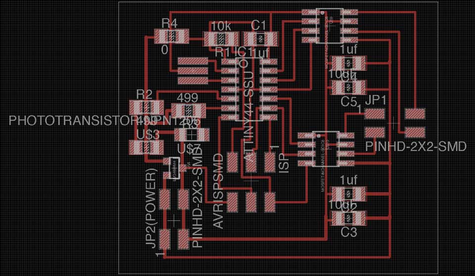
I started redoing from scratch lightboard hello, using H-bridges instead of Attiny. I also put the finer lines to don't have problems again.

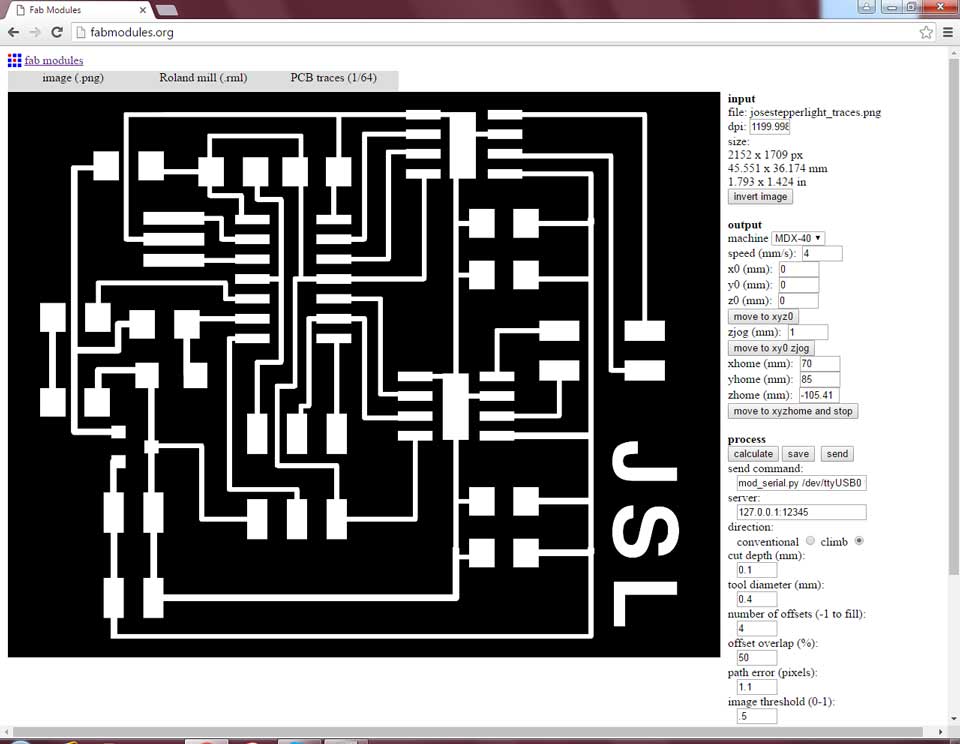
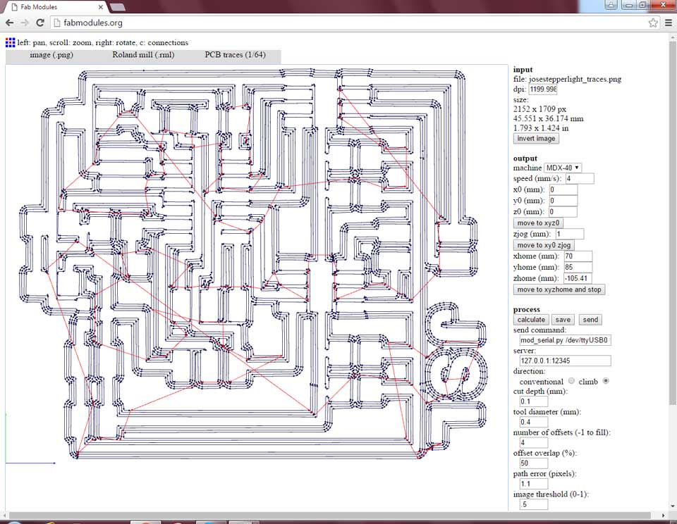
Milling it.
PROGRAMMING
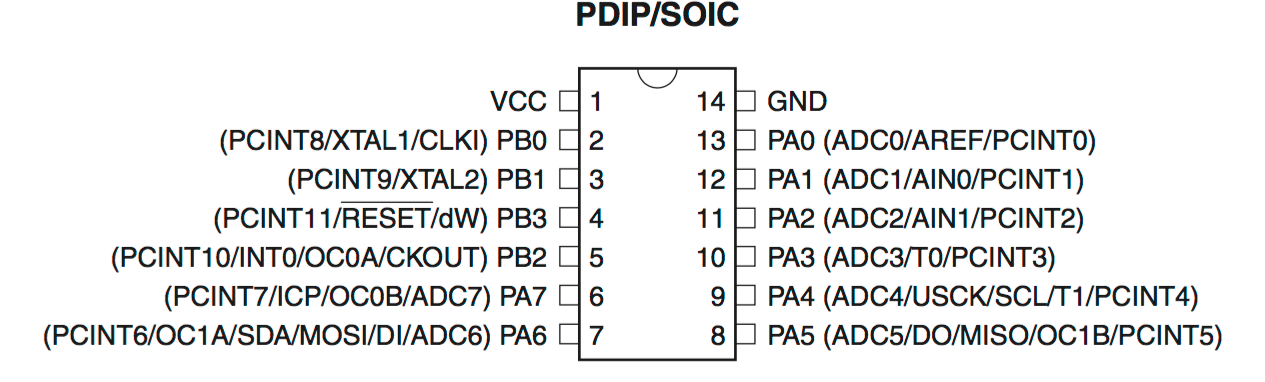
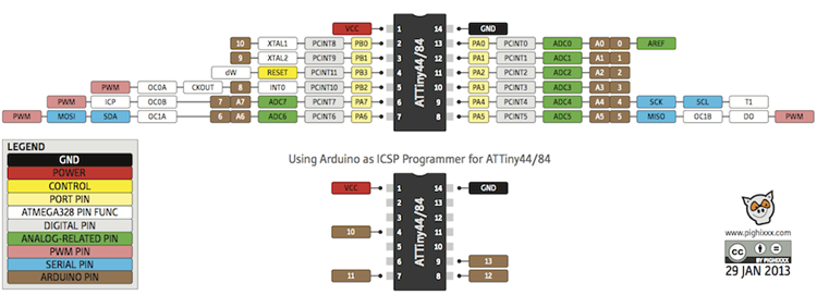
To know about the datasheet of the Attiny44 I consulted this scheme and the Arduino Pincode with this microcontroler.:
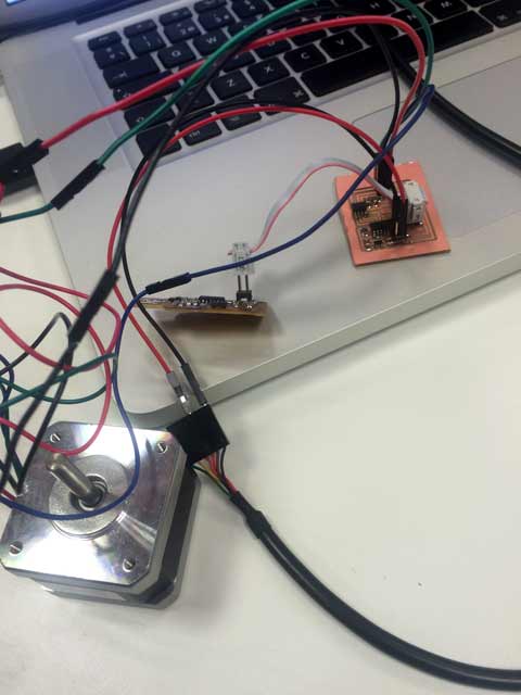
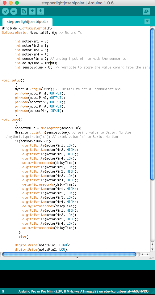
First I have programe it with the hellostepper without the light sensor in Arduino Code. After checking cables from Nema 17 I've tried various positions until it worked properly. To know where are the Rx and Tx pins to use SoftwareSerial, the pins for the motors (0,1,3,4) and the sensorpin (7). I can detect them into Eagle scheme file and the board.

LightStepper beta from Jose Real on Vimeo.
To set the light sensor I needed to know which pins were free.
In this case Rx and Tx were 6 and 5 and the pins 0,1,3 and 4 were busy to transmit the stepper motor. To know phisically where are this pins I have see it in Eagle.
It's works!!

Lightstepper working from Jose Real on Vimeo.
PROGRAMMING V2.0
Now I want to use Arduino again and change the code. I would like to use a better one. First I need to use the sensor values again, so if the sensor is 500 or more, the stepper will moves to one direction and if the value is less the sense of the moves is the opposite. I want to print the direction in the monitor with this symbols (<,>).
Programming the board.


#include <SoftwareSerial.h>
#include <Stepper.h>
const int sensorPin = 7; // analog input pin to hook the sensor to
int sensorValue = 0; // variable to store the value coming from the sensor
const int stepsPerRevolution = 200;
const int UMBRAL = 500;
SoftwareSerial Myserial(5, 6); // Rx and Tx
Stepper myStepper(stepsPerRevolution, 0,1,3,4);
void setup()
{
Myserial.begin(9600); // initialize serial communications
myStepper.setSpeed(120);
pinMode(sensorPin, INPUT);
}
void loop()
{
sensorValue = analogRead(sensorPin);
Myserial.print(sensorValue); // print value to Serial Monitor
if(sensorValue > UMBRAL){
myStepper.step(10);
Myserial.println('>'); // print value to Serial Monitor
}
else{
myStepper.step(-10);
Myserial.println('<'); // print value to Serial Monitor
}
}
WHAT I LEARNED?
This practice has been especially difficult for me because I lost a lot of time researching my own faults and seeking solutions.
I learned a lot about the connections and capabilities of the microcontroller and how to find faults with the multimeter.
The other problem is learn about datasheet. The pincodes are not difficult,If I'm wrong one, nothing works.. It's very important to have a good program.
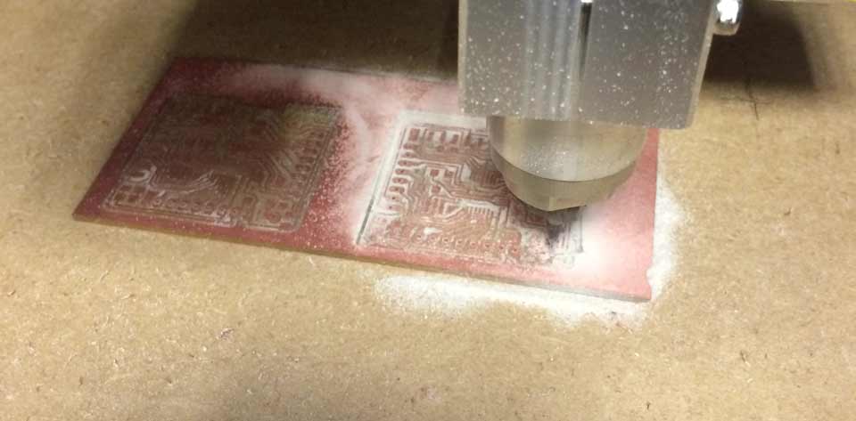
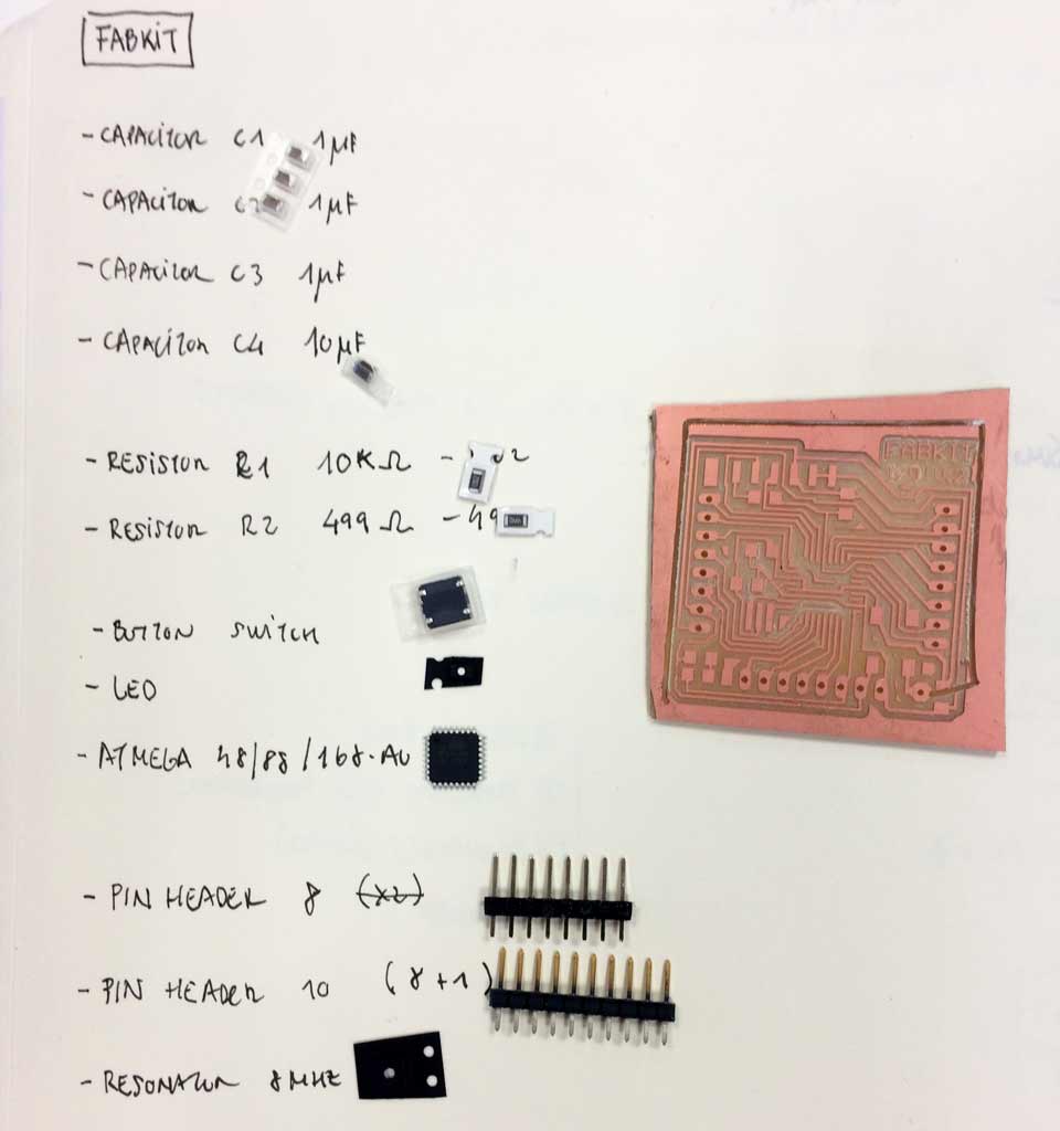
FABKIT
Now I'm working in try to use a Fabkit. I have soldered and must be programmed. I have a problem cutting it, the board is taken off. I left the not harm my colleague Marta and I fixed mine. At least only he cuts one of the tracks!
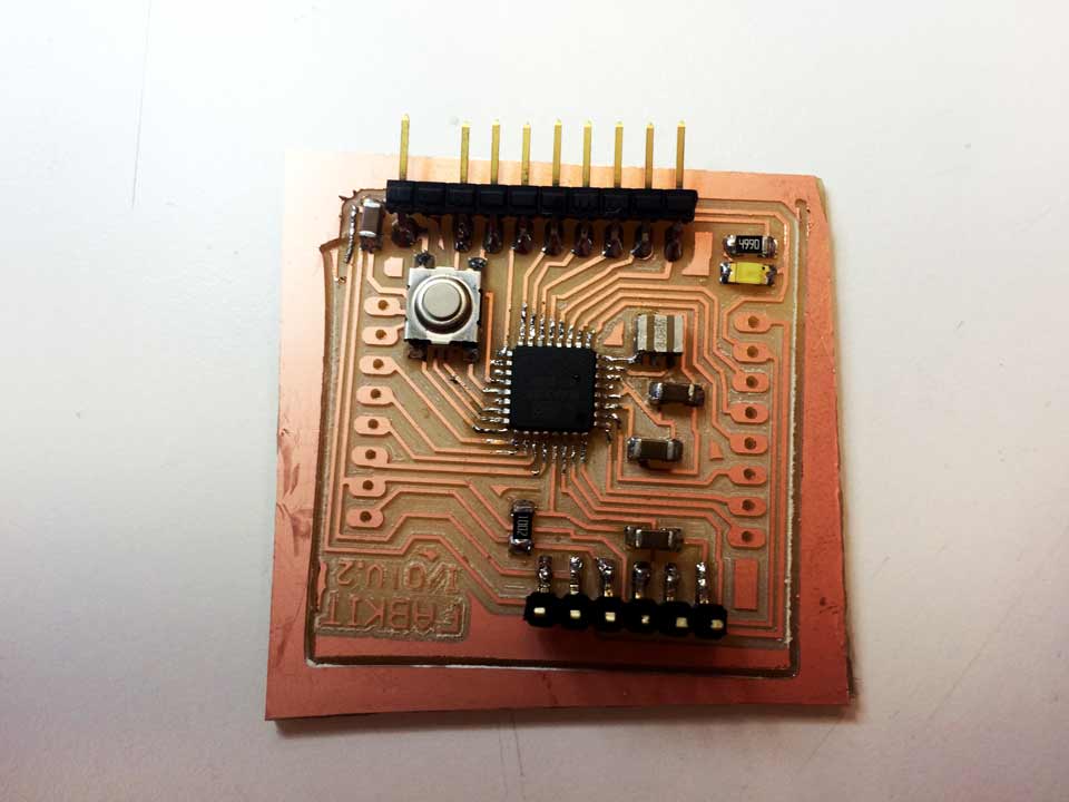
I have some problems programming the Fabkit, It be described in my final project page.
OUTPUT DEVICES |
|
Described your design and fabrication process using words/images/screenshots |
x |
Explained the programming process/es you used and how the microcontroller datasheet helped you |
x |
Outlined problems and how you fixed them |
x |
Included original design files and code |
x |
-----------------------
FILES
joselightstepper traces + cutout
eaglejose light stepper scheme + board + png traces + png ext cut