 JOSE REAL
Week 6 - Electronic Design
Create our own project of a hello world electronic board. Add a button and a LED.
Introducing to EAGLE. Design.
It’s my second time working with a board and my first time designing it.
The workflow was to learn about basic electronic design with Nuria Robles (FabLab Leon). We had an online class, Nuria told us how to use the program, add libraries, how to connect components, etc. We use Eagle because is easy to use and it’s very common program to design.
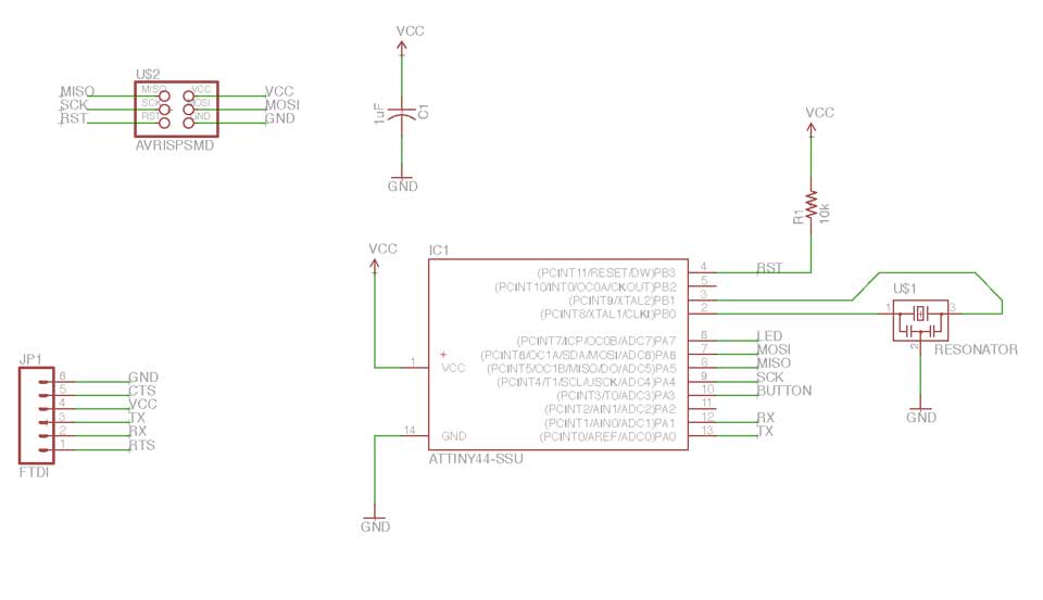
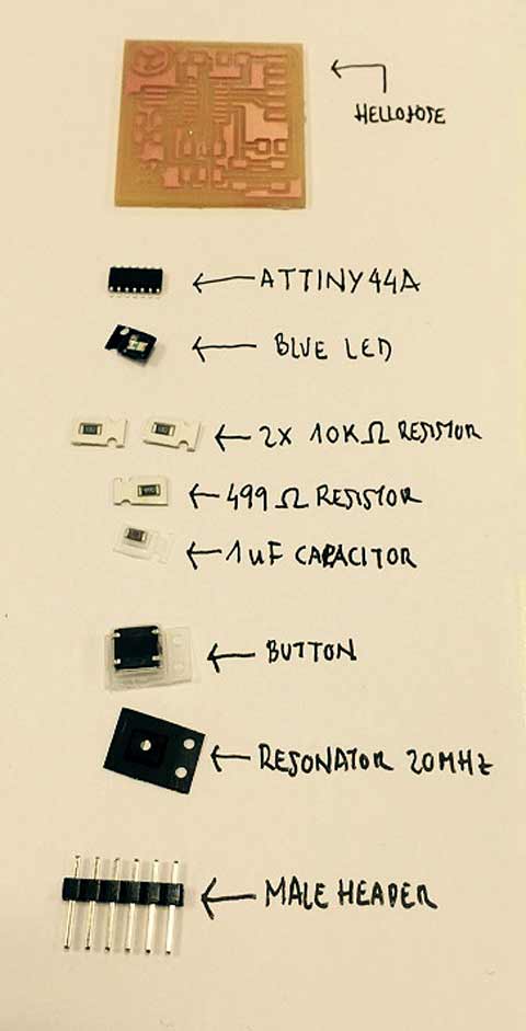
There are the components we need:
- Resonator 20 MHz
- Capacitor : 1uF - Resistor : 499K Ohm (RxES 499 OHM 1-4W 1% 1206 SMD)
- Resistors (x2): 10uK Ohm (RES 10.0K OHM 1-4W 1% 1206 SMD)
- ATTINY 44-SSU - AVR ISP
- FTDI-S ( 1X06SMD)
- LED. Blue clear (The negative pole will be oriented to ground)
- Buttom (SWITCH OMRON SWITCH) We learned how to use the program with an existing board, but for our practice started from scratch, adding components. The difficulty was finding the appropriate libraries for each component.
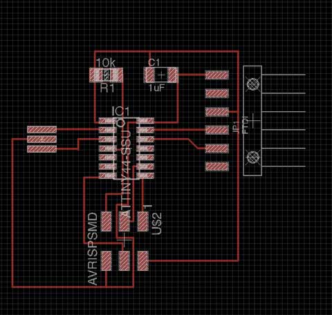
We had to add tags and attach components with Label and Wire buttons. I had a lot of problems adding all the components generating the board so I re-started, first designing the Hello board and once done adding the button and the LED.
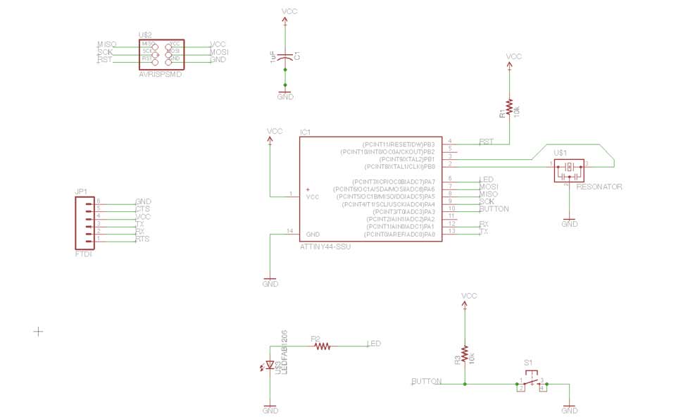
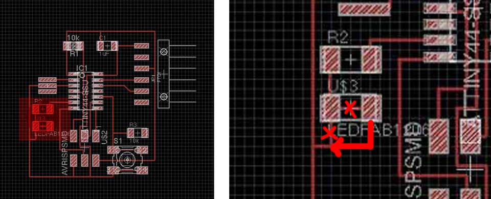
The next step was add the button and the led:
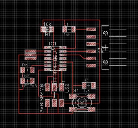
There was a problem because the wires that pass under the ATTINY are too near, to solve the problem I changed it in “ File / Design rules”...but I was not aware of other problems when mill the board.
I added things to the board with photoshop and make the rml with the fabmodules .

Milling and soldering
I have milled using Fabmodules and Vpanel.
In this practice I used the recommended parameters:
Speed 4 mm // this is the speed machine when it mills
zjog: 2mm
cut depth: 0.1 // this is very important because is I use more than this the mill will broke. When board is bended I make more passes (0.2-0.3 etc)
number offsets: 4
For the exterior cut I used less speed (0.5mm/seg) and the cut depth higher, 0.6 mm. the boards is 1.7 mm aprox so I can cut it.


There are all components and the board:
It have some problems. First one was that "hello jose" didn't milled.
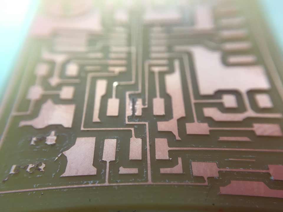
I saw that Marta’s plate’s problem was the proximity of wires, inspected mine and found something:
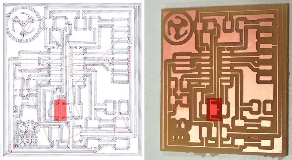
The closest wire is too near and the mill dind't cut. I solved it with a "handmade" mode.
NOTE: This error is caused when the dpi is low, it is recommended to use from 1500 dpi for a better result (not as in my example, 500 dpi) The document should have exported with more dpi from Eagle.

I have started to solder and my board has more problems...
I found that I was wrong with the design! I don't want to start again so I made a "special solution" on the board with a cable and tin.
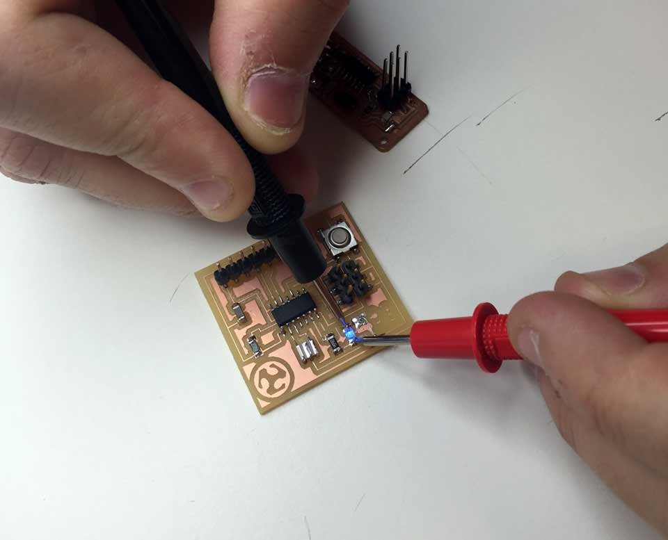
It's works!!! In this pic you can see the "special fix"
What I have learn?
To design any a board you need to know the distance between rails so that the mill can pass between them and not join them. In case it doesn’t enter it will not cut it.
ELECTRONICS DESIGN |
|
Shown your process using words/images/screenshots |
x |
Explained problems and how you fixed them |
x |
Done fabbercise today |
x |
Included original design files (Eagle, KiCad, Inkscape - whatever) |
x |
hellojose eagle_ board + scheme
hellojose_cutout.png + hellojose_cutout.rml
hellojose_traces.png + hellojose_traces.rml