ELECTRONICS DESIGN
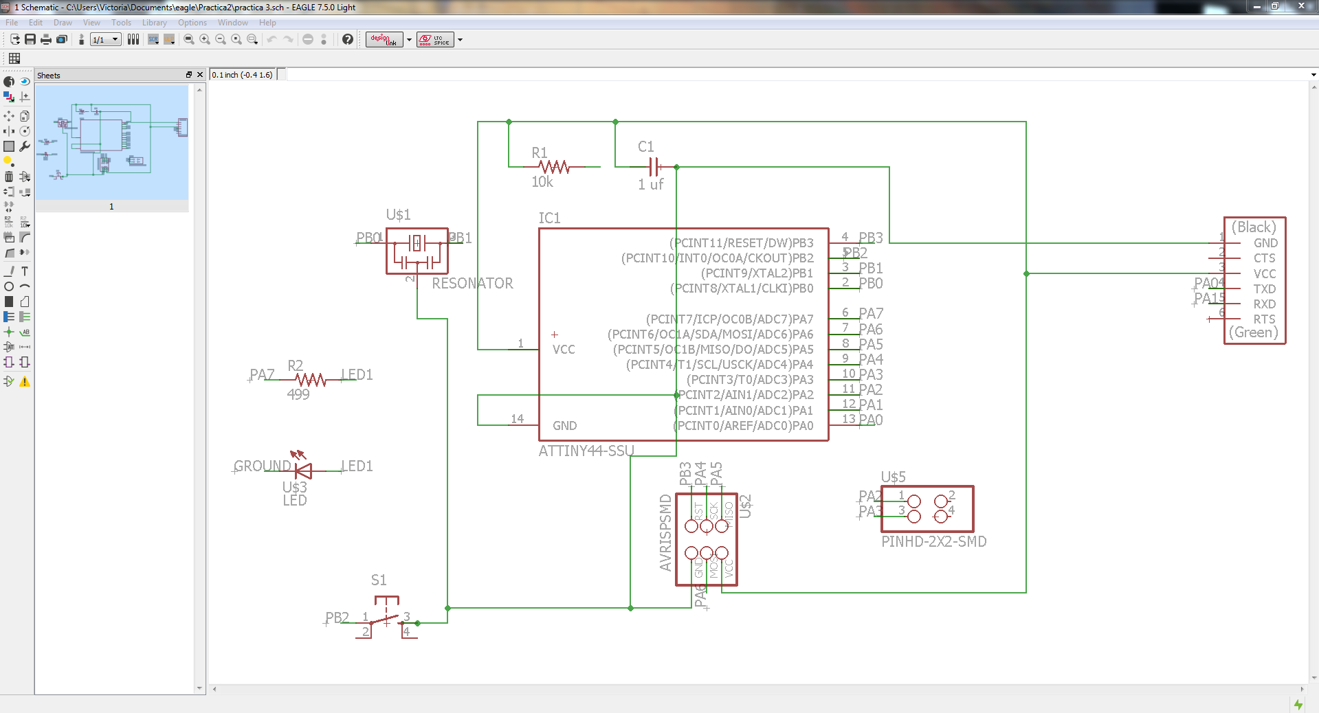
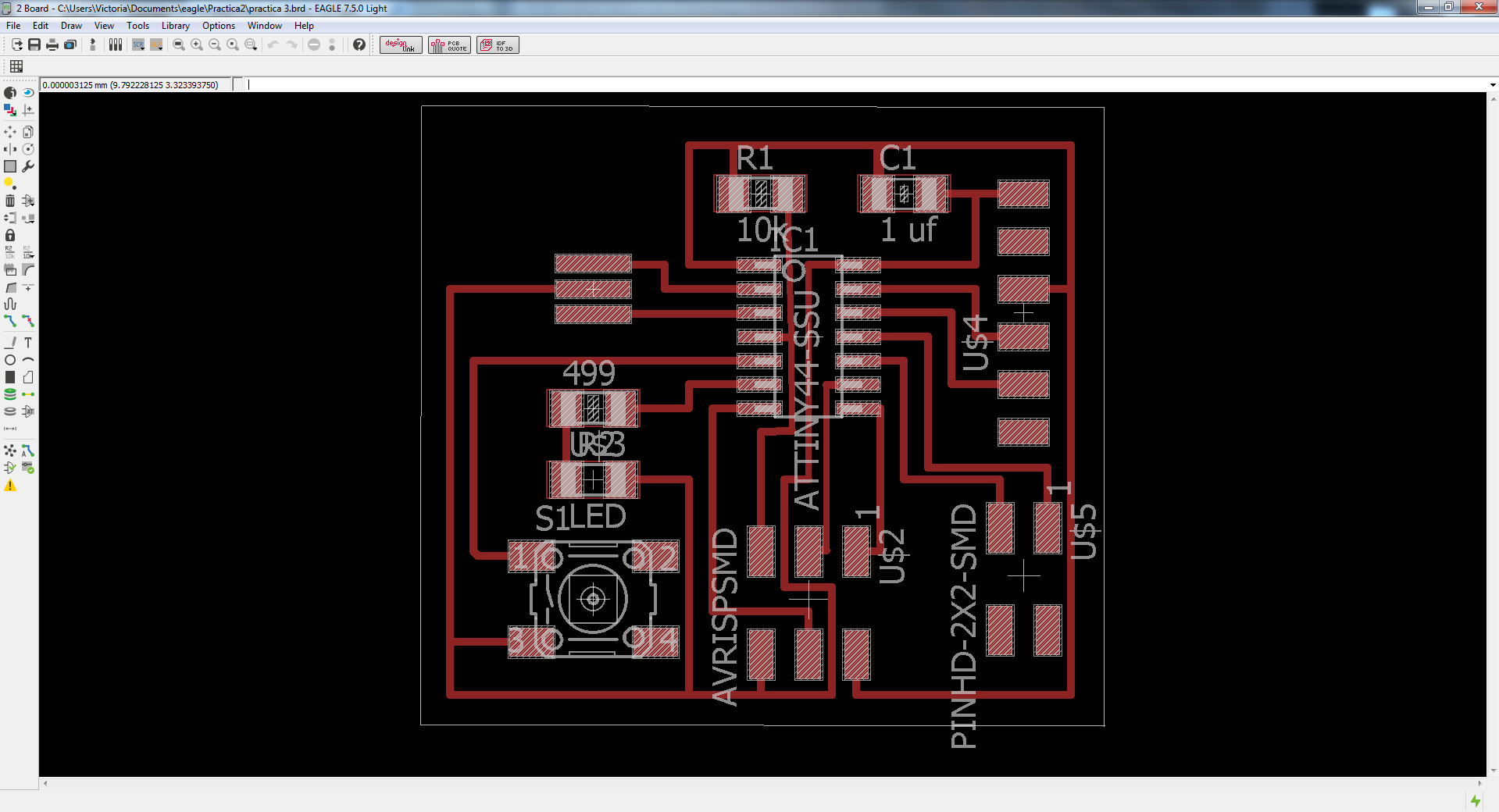
The assignment for this week was to redraw the hello-world board adding at least a led and a button, I also added a J3 US1 Header in order to have the possibility to use it in a future.
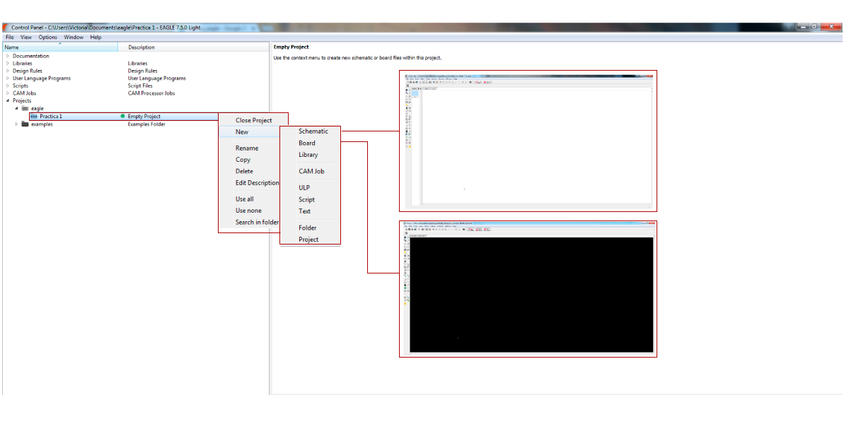
To redraw the board I used Eagle, for me it was the first time that I used it and I had some problems when I changed the schematic view to the board view because some of the connections in the schematic view seemed connected but there weren’t connected but I solved it.
First I did the component’s list:
Hello world components:
- 1 Capacitor 1Uf
- Microcontroller Attiny44
- Resonator 20 MHz
- Resistor 10.0 K
- J1 ISP Header
- J2 FTDI Header
New components:
- Button SWITCH TACT
- Led LED GREEN CLEAR Voltage 10MA
- Resistor 499 Ω
- J3 US1 Header
To calculate the needed resistor for the led I used the Ohm Law, as I don’t have any resistor of the calculated value I took the next resistor value which it was 499 Ω.
V= I*R
I= V/R
R=V/I
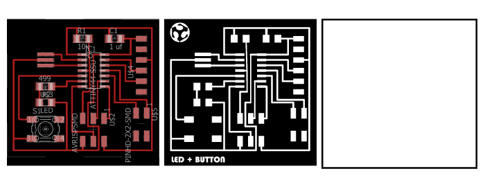
I used Photoshop to do the exterior png file and to add a drawing and a text to the traces png file but some parts were too small for the mill and it didn’t cut it.
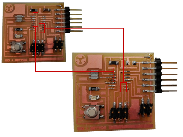
I used the Roland Mill MDX-20 to cut the board and at the beginning I couldn’t cut the board because I didn’t let enough space in z axes but I realized of it and I solved it.
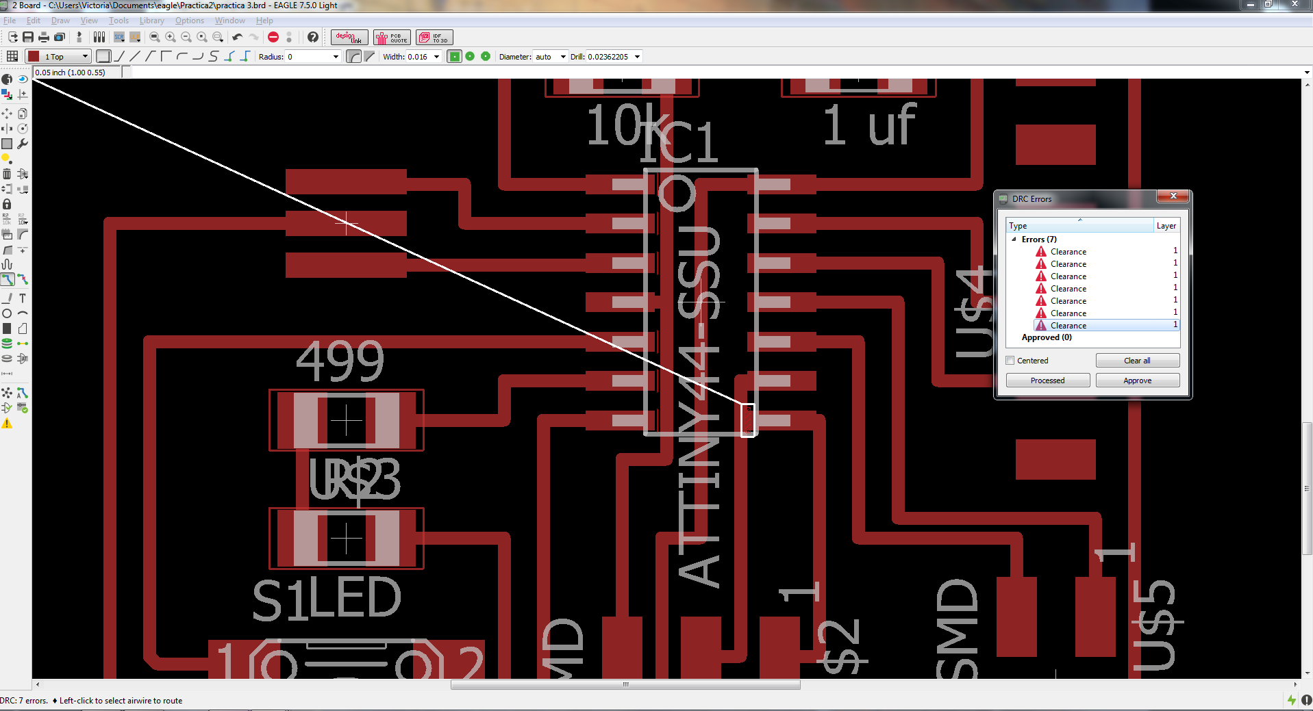
As the first time that I cut the board I couldn’t cut it when the mill was going again to the 0 it went drawing a diagonal, so it cut a small part of wire but I solved it using pewter.
Another mistake was that when I checked in Eagle the errors and warnings I did it with another design rules file different to Roland Mill’s design rules file, so when I cut the board I realized that two wires were too close to each other so I cut it using a cutter.
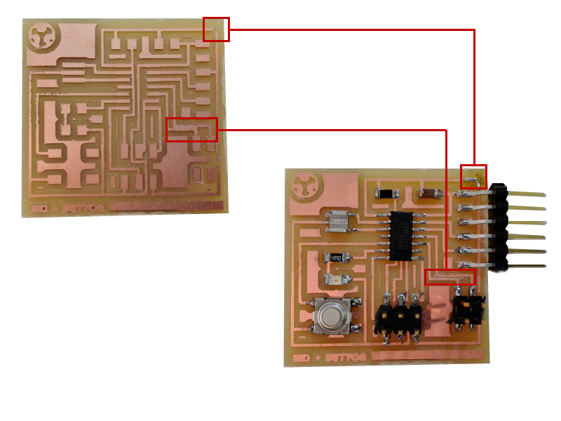
Two weeks later in the embedded programmming class when I was trying to program the hello world board it didn´t work and checking the board again I realized that there were a few wire conections that shouldn't be there so I desoldered the microcontroller and I cut the wires using a cutter, I think that the problem was that I didn`t used the correct checking rules.