

The assignment for this week was to measure something: add a sensor to a microcontroller board that you have designed and read it. I selected the phototransitor light project as it will best dovetail into what I wanted to create for my final project. My final project will involve using sensors to count the number of people entering our FabLab and displaying it on an LED sign. The light sensor has the most crossover to my project.
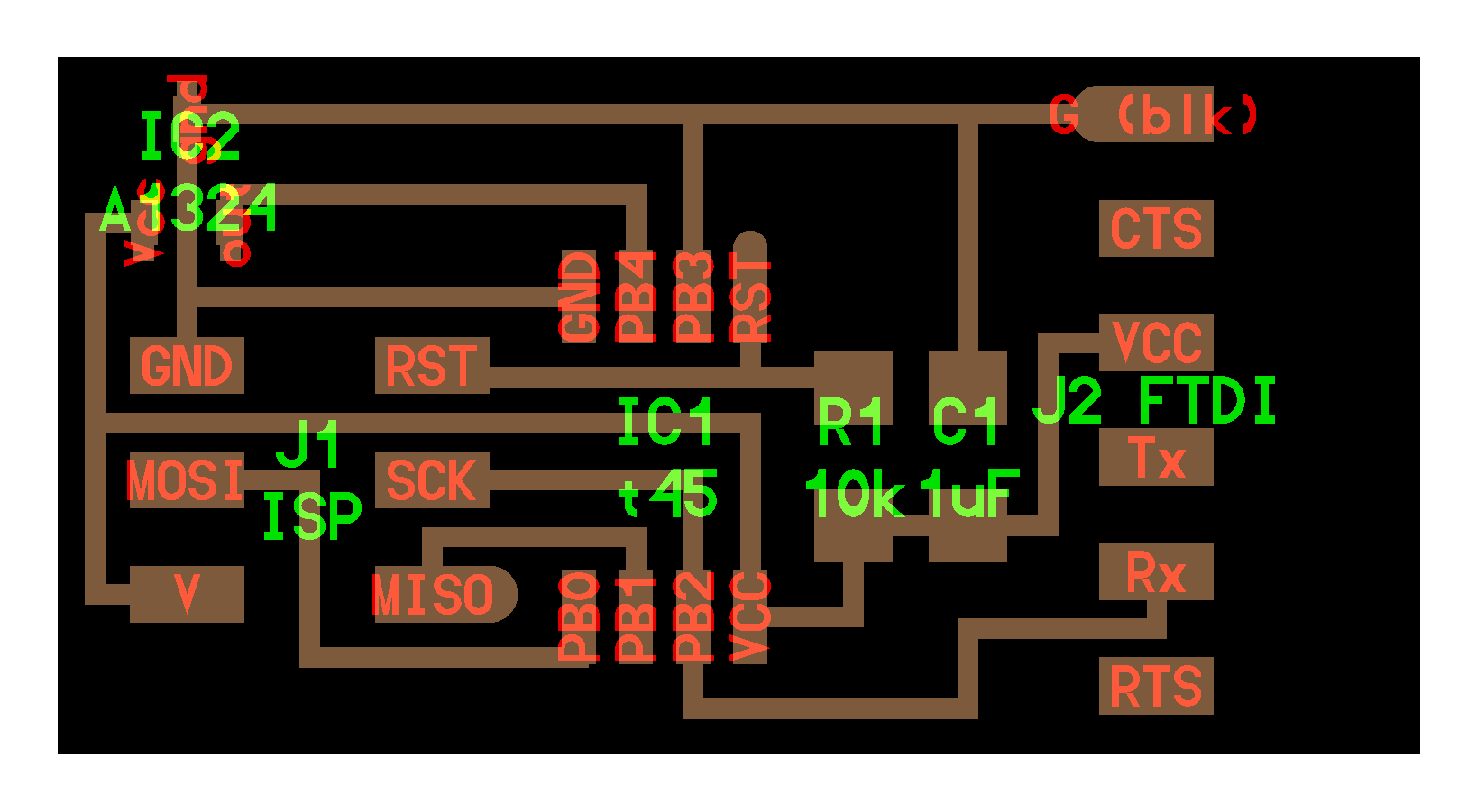
I opened up Eagle to start the process of designing the board that was sketched out by Neil on the FabAcademy Page. I went to Hello.Light.Board to see the board files and what I would need to populate my board and schematics in Eagle. I opened up the Fab Library I had installed in Eagle for the circuit design unit. I was able to add components to my schematics by either command line or using the GUI Add button in Eagle.
To create the schematics, I needed the list of components that I needed for the board. Once I secured the components needed I could easily choose the correct component from the fab.lib in Eagle to create the schematic. The components I needed were:
I then opened up Eagle and started to create the schematic for the board. I was a bit rusty as it had been a few weeks since I had last used the program. I quickly then started to use the GUI as it made it faster for a novice like me. I very quickly started to add all the components and then the labeling process began. This made it easy to connect all the GND's together and as I labeled the schematics it all started to tie together.
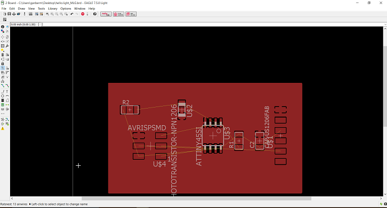
It was time to convert the finished schematic into a board file.

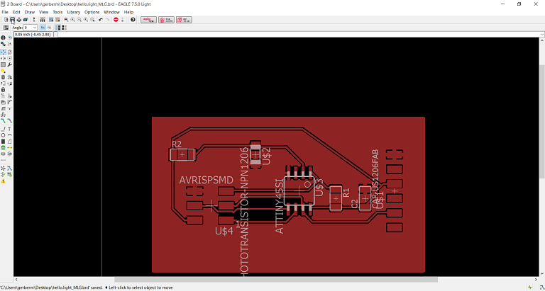
The next step was to be able to place the components on the board. In Eagle I switched over to the board view. I was then able to start placing my components to create a traces on the board. The components were placed in the corner with the yellow lines attached. I then looked at Neil's board to get a sense as to where to place the components for efficient traces or routes on the board. It provided me a sense of where to potentially place components. I then started to sort the components on the board. It was fairly easy to drag the components around.
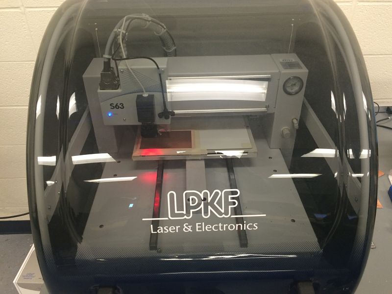
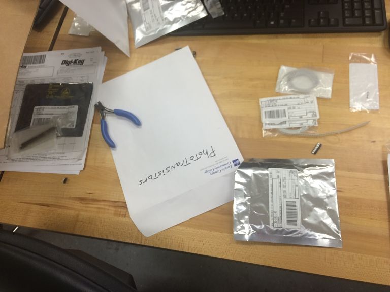
I then cut out the board and assembled my components. I cut out two boards as I have had issues with pulling up the traces or my board not working so I decided to cut two boards and solder two boards. This is good practice and insures me against not getting my board to work correctly. As it turned out I am glad I did this as I had to troubleshoot my board for a few hours to see why it did not work correctly. I also went through the LCCC FabLab inventory and taped the parts I needed to a piece of paper to help me as I populated the board. I even used Neil's advice and etched the name of the project and my last name on the board to keep track.


I then took the components and populated the board. I enjoy the soldering process and using the microscope and soldering has become much easier for me. I like the challenge of small and complicated solding. This process can be frustrating as the flux does not tack it down or it is difficult to solder such a small contact. On this project the phototransitor proved to be difficult as the contacts were on the bottom.

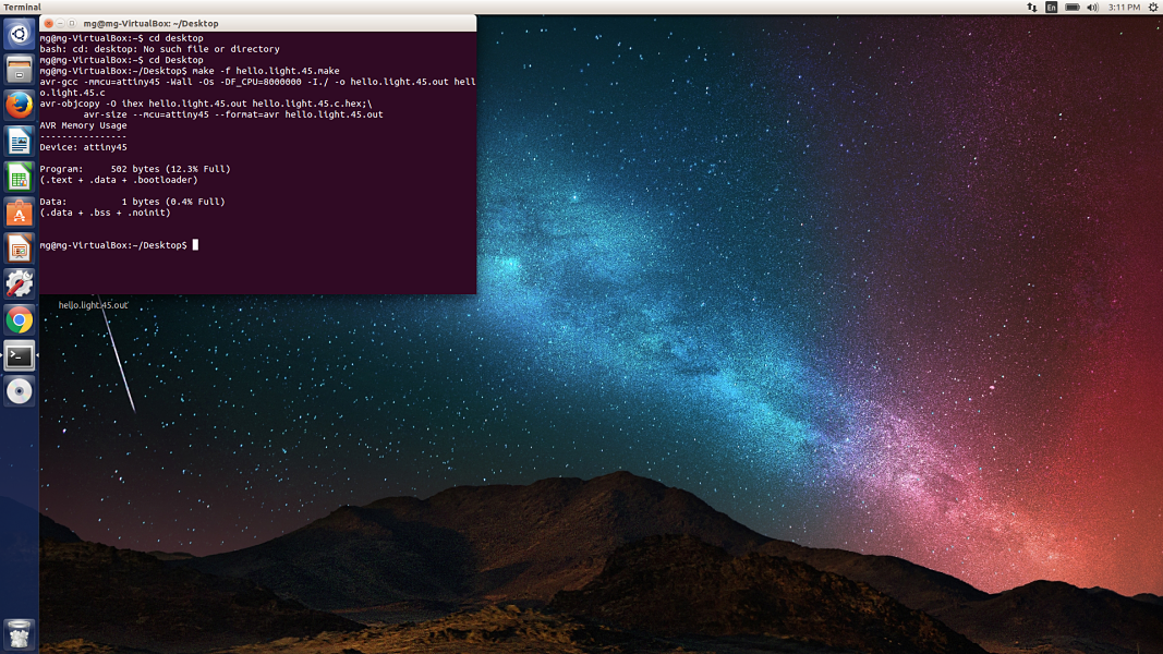
I then flashed and compiled the program files on my board and everthing seemed to work. I downloaded all the files from the FabAcademy site to my desktop on Ubuntu. The files I downloaded to the desktop were:
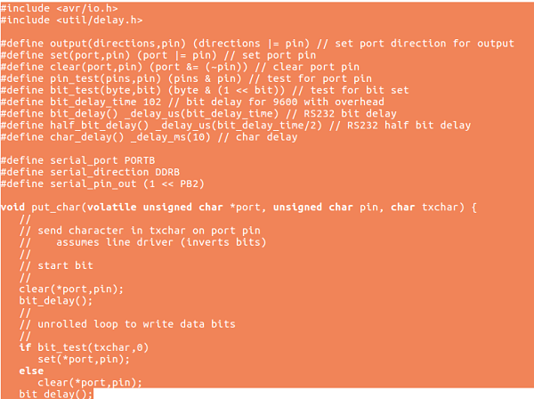
hello.light.45.c, makefile and hello.light.45.py. The process I went through in programming the board. I used Neil's files as my board's pinouts were exactly the same
as the one's in Neils example. The code written by Neil starts by the #include


The Sensor and Challenges
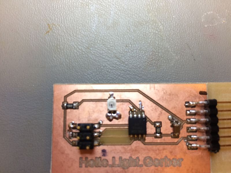
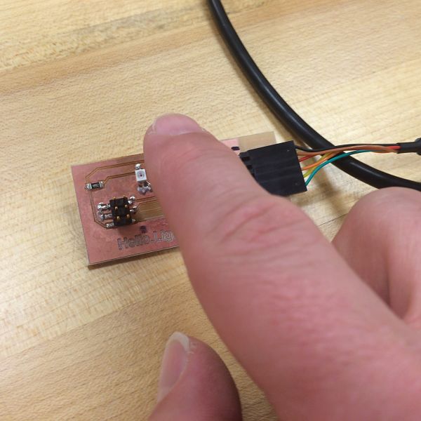
I then ran the python program and the board did not fluxuate very much when I placed my finger and obstructed the phototransitor. It was not like the video illustrated on Neil's page. I was frustrated and started into my troubleshooting mode. This was done by heating up the transitor and replacing it. This did not result in the desired outcome. I put each part under the microscope. I turned around the phototransitor as I had it backwards, this still did not result in the desired outcome. I finally found out the phototransitor has ground contacts and was touching the ground by a milimeter. This caused it to not work correctly. When I moved the phototransitor up slightly, it worked as intented.

You can see the short on the board just slightly down touching the ground
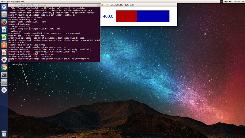
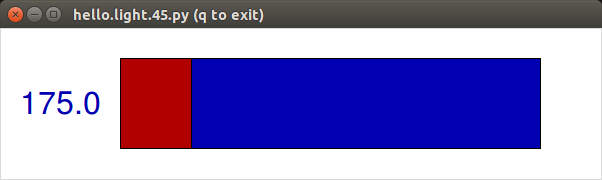
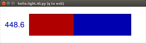
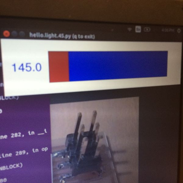
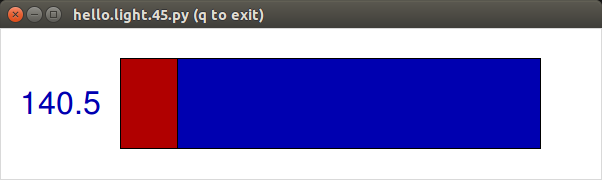
After I fixed the phototransitor, the board worked as designed. As I moved my finger over the sensor the output changed due to the altering of light on the phototransitor. You can see the values changing from 400 to 145 to 175 to 448 to 140.
Project Files: