The assignment this week is three fold:
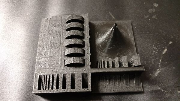
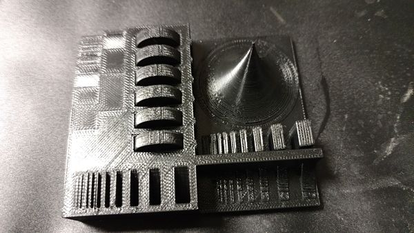
The group assignment was to test the printing limitations or design rules for the two 3D printers located in the FabLab. There is two 3D printers located in the lab a MakerGear 2 and the Dimension Catalyst. We really tested the 3D printers available to us in the LCCC FabLab. It was interesting to see the contrasts between the MakerGear 2, a consumer 3D printer manufactured near us in Cleveland that costs around $2,000 USD and the Dimension Catalyst, a business/ professional grade 3D printer made by Stratasys. We as a group tested the tolerances of each machine to see how it performs with support material, wall thickness, geometric shapes and shrinkage. We used a variety of materials and tested each printer for tolerances.
The boundaries of the MakerGear 2 are:
This is the test piece printed off the MakerGear 2 used to find the tolerances

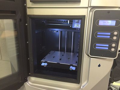
Dimension SST1200es 3D printer with CatalystEX using ABS material and dissolvable support
The boundaries of the Dimension Catalyst:
This is the test piece printed off the Catalyst to find the tolerances
This week we learned about 3D printing. It was a fascinating discussion of the differing types of printing methods, the origins, evolution and future of 3D printing. We also focused on the drawbacks to 3D printing. I found the entire lecture engrossing and deepened my knowledge and understanding of 3D printing. 3D printing has also been successful at the consumer markets as of late in bring prices down and quality up for the hobbyists. Neil also focused on a great point about most of the 3D printing should be done in a different manner that is more appropriate. I agree and see 3D printing as more of a weakness than strength for most applications. The additive process is not a good as the subtractive process for most appliations. It is the few applications that concern geometry that you cannot fabricate any other way. This was the challenge for us.
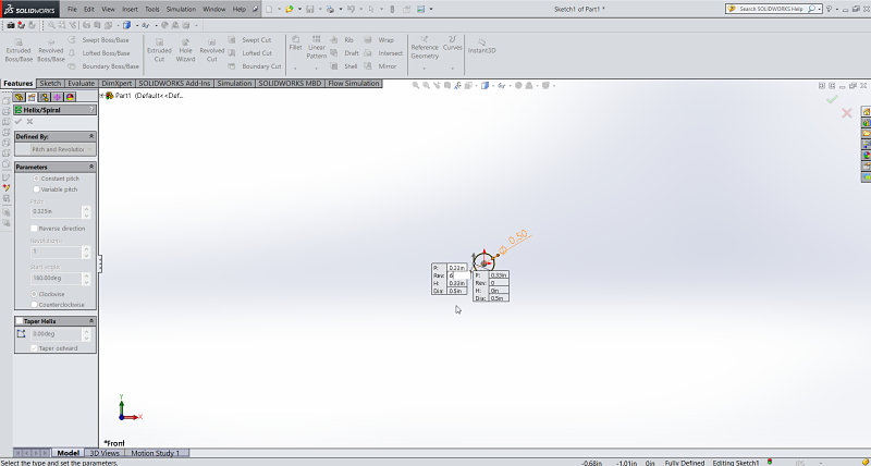
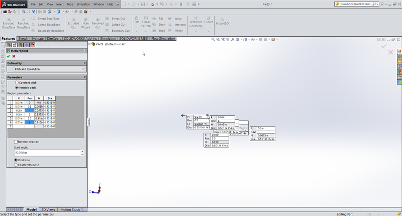
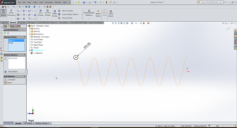
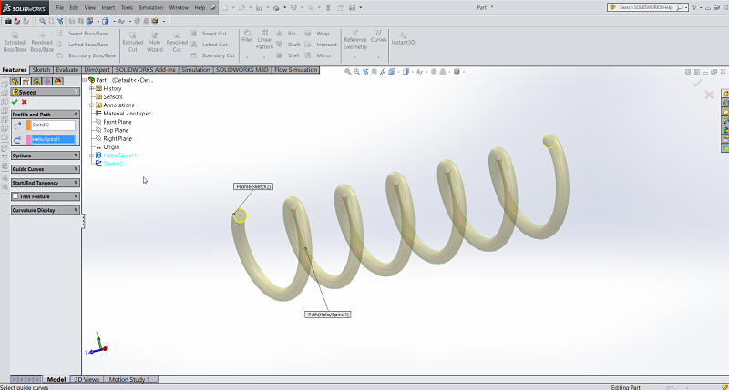
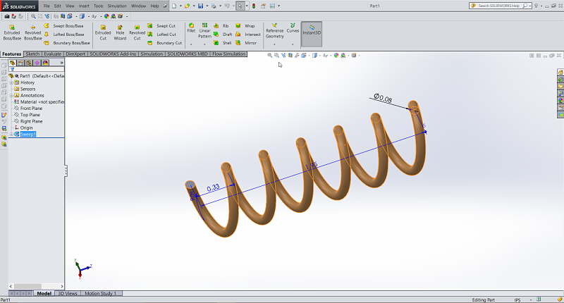
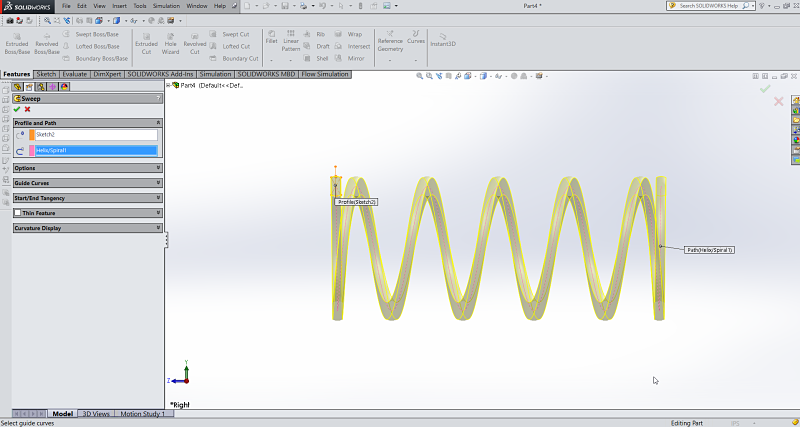
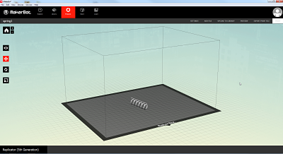
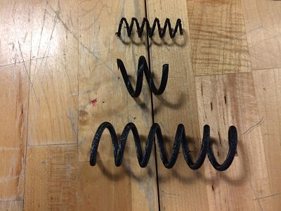
I decided to create a spring using Solidworks. It found it an easy process and tried to keep the spring to a few cm as was suggested in the assignment. I also wanted to test tolerances of my 3D printers. I used three 3D printers and three different software packages to print the spring. The spring could not me made subtractively and the diameter of the wire on the spring was very thin to put pressure on the 3D printers to print it with and without supports. I started by creating the wire diameter, then the wire dimensions, then the spring length and the spring ends which I decided not to ultimately use. The process using Solidworks as illustrated below was fairly straightforward. I had to create a helix by making a sketch with a circle. The circle is the will be the helix's diameter. I then used the Features tab and selected, Curves, Helix and Spiral from the icon. I selected Pitch and Revolutions from the Defined By drop down menu and defined the pitch and revolutions. I played with the start angles. The images show the helix and now I needed to add a profile sketch for the sweep. I added a Pierce between the center of the circle and the helix. This allows for it to start at the beginning of the helix. I then used the Sweep command using the last sketch as a profile nd the Helix as a Path. This created my spring and is illustrated below.
Creating the file in SolidWorks.
I then exported the .stl file and started the process by printing it on the Makerbot Replicator in my office. I used the Makerbot Desktop software to get the file ready to print. I do not think the Makerbot desktop is a great program and has many limitations based on my experience using Simplify 3D and UP software. I also wanted to see the tolerance for printing my spring in which the diameter of the spring was very small. The other issue was should I print it standing up or laying down. Did I need to use a raft to print it on or should I just print it without a raft? These were just some of the questions to answer from my experience using 3D printers.
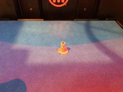
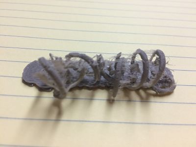
Spring In Makerbot Desktop, Printing It Standing Up, Printing On Side, Crushed Spring Because Support Material Broke Spring
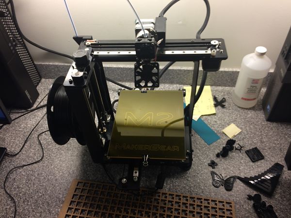
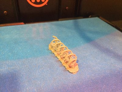
I then decided to print it in a Maker Gear 2 printer at the Fab Lab using Simplify 3D. Simplify 3D is a very easy to use program and compiles the print files extremely fast in relation to Makerbot Desktop. I decided to print it both laying down and standing up to see how it would print. We also decided to clean the heated glass plate it extrudes on after a few pieces kept sliding off the platform.

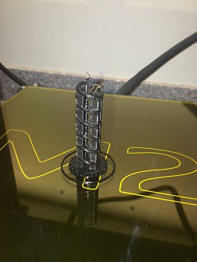
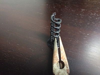
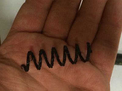
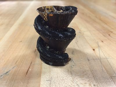
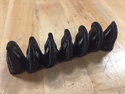
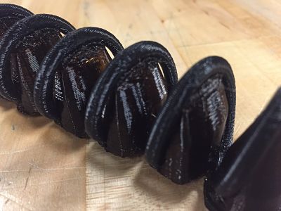
Maker Gear 2, Failed Printing on Side, Printing Standing Up, Final Spring With Supports, Cleaning Up Spring, Spring In Hand
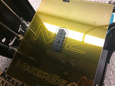
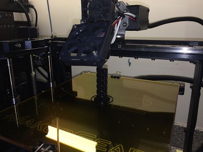
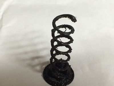
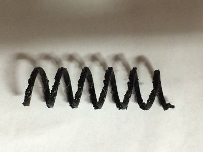
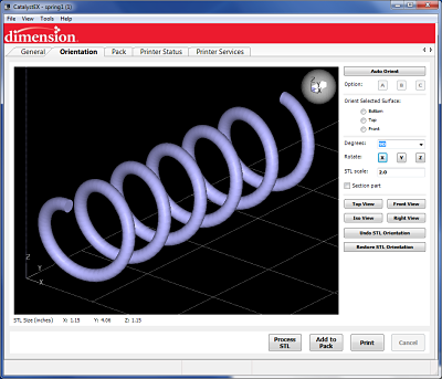
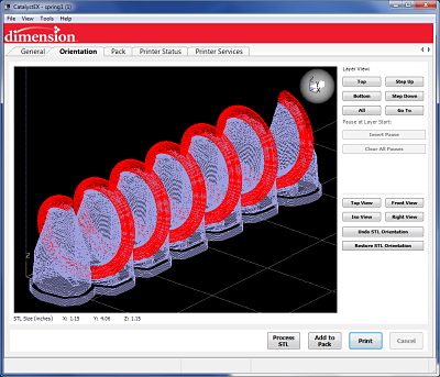
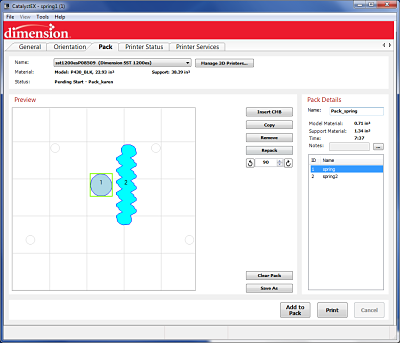
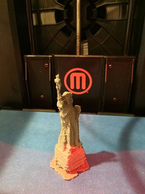
I then decided to print it on the industrial Dimension Catalyst 3D printer in the Fab Lab. This was relatively easy as I exported my spring1.stl file and had it position it on the print bed. It added supporing material and when I am finished, it will dissolve the support material.
The Dimension Printer, Laying Print Down, Supports For Spring, Print Layout, Spring With Supports, Print Without Supports
I decided to scan an object using our Afinia ES360 3D scanner with turntable. This is a white-light scanner using light phase technology without the use of lasers. It produces a 1.3 megapixel resolution and can output to .STL, .ASC or .OBJ file formats. I purchased a small 4" Statue of Liberty figurine in New York City that I decided to scan. I figured the Statue of Liberty would provide enough detail to determine how effective the scan would be.
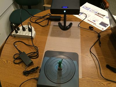
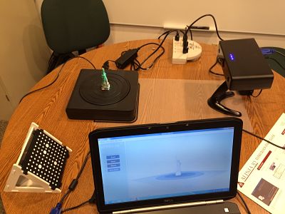
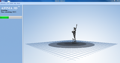
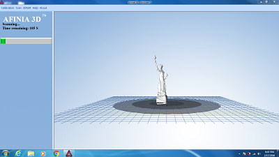
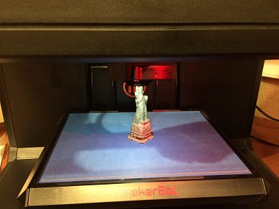
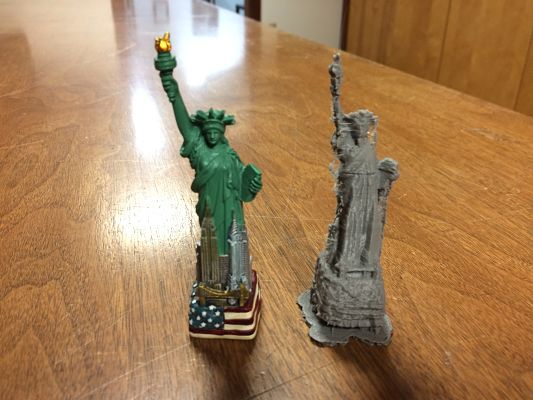
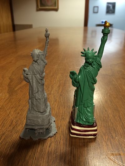
The Affina Scanner, Scanning The Statue Of Liberty, Meshing Statue Together, Printing on Makerbot Replicator, Front and Back Images for Comparison
I tried a variety of settings and lighting to determine the best way to use the scanner. It is a budget scanner but does a decent job of scanning small objects and using the turntable helps to scan parts. I would much prefer the quality of a handheld scanner but cannot justify the cost for an object I don't use all the time.
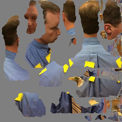
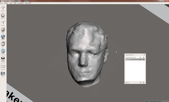
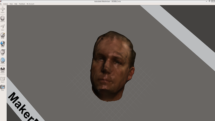
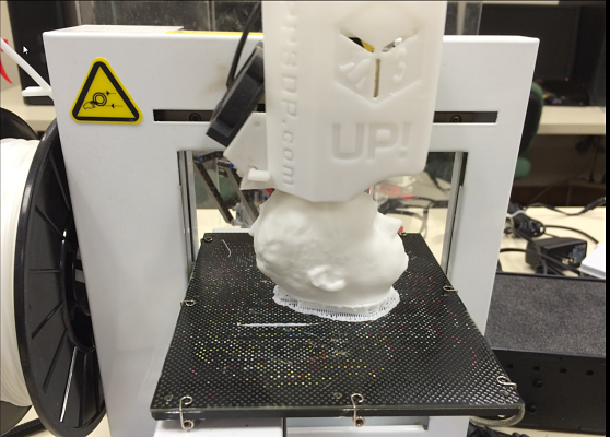
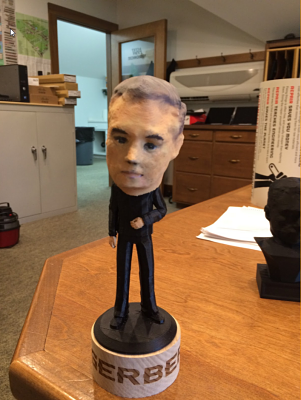
I installed 123D Catch on my iPhone and decided to try to make a bust of myself and maybe a bobblehead as well. The app was free and did a decent job creating a file that I imported into Meshmixer to fix the mesh and clean up the image. It was a fun project and I could definately see doing something like this with my students to get them interested in 3D printing and themselves. I first put yellow post-it notes around my body and then had someone use my phone and take pictures of me. It then took awhile to upload all the pictures in 123D Catch but I was able to then take the file to Meshmixer and clean up the image. I then used Meshmixer to cut my neck off and hollow out the head to put a spring inside the bobble-head. I printed a body from Thingiverse. I printed the head on a UP Plus printer in white PLA. I then took the head and air brushed my face and painted eyes on the head to give it a sense of realism. I also laser cut my name on a block of round wood I found in the shop and glued the base to the wood block with my name on it.
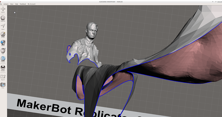
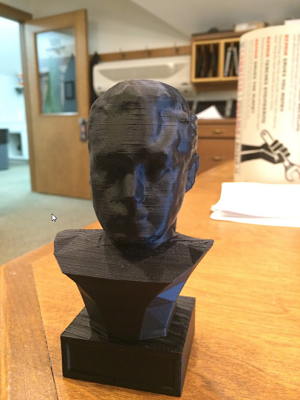
I then decided to add my head to a statue body I found on Thingiverse to create a bust using Meshmixer to join the two objects. I then printed that out on our UP Box 3D printer. It turned out great for the amount of time I put into the bust. I find Meshmixer to be very user friendly and free for schools to use to edit the triangles in the .stl files.
The Process Of Starting With Pictures, Meshmixer, Makerbot, Final Products
Project Files: