The assignment for this week is to write an application that interfaces with an input &/or output device that I made and compare as many tool options as possible.
I will perform the following:
As I watched the lecture by Neil, I was amazed at the amount of languages and applications that can be used to interface with and program a board we used. I decided to use the hello.light board I made in Week 11 for our
input devices. I was determined to write an application program using the phototransitorbased light sensor. I started by going through the programming languages. I decided I wanted to try to hack the python code for the original file and
use Processing to code using visual arts.
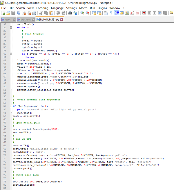
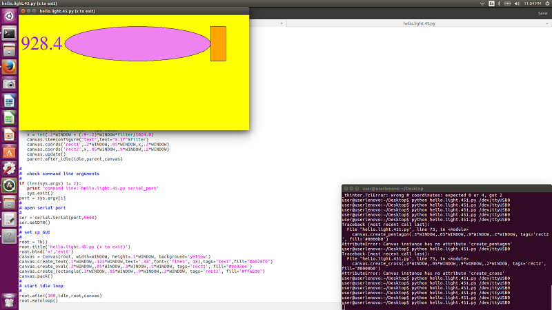
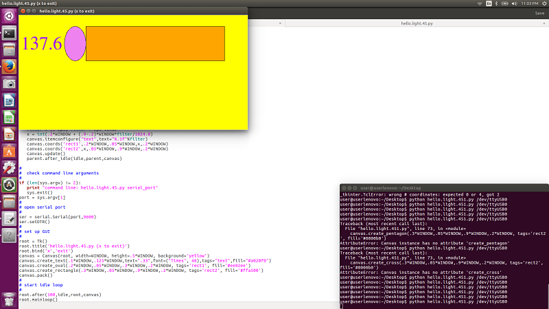
I started by opening up the hello.light.45.py file that was written by Neil. I decided that I would look at how it was written. I opened it up and renamed it hello.light.451.py. I then started to look closely at the code that it contained. I decided to change the variables. I changed the colors first to see what it would look like. I then changed the rectangle to an oval and the overall size of the display by changing the window sizes. I then changed the exit from q for quit to x for quit by changing a few variables in the code. It was interesting to look closely at the code and change a few variables but I did not really accomplish anything other than look closely at python and Tkinter. I plan on learning more python but for now this very surface level of knowledge will have to suffice.
Here is a video of the hello.light.451.py interacting with the phototransitor and changed variables from the original on the screen.
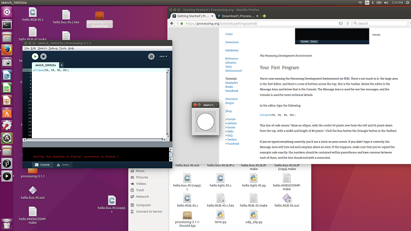
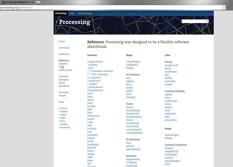
I was intrigued by the programming language Processing mentioned by Neil. It is close to the same feel as Arduino and I decided to write a program in Processing to interface with my light board. I wanted to visually change the screen when the phototransitor values changed. This could be accomplished using Processing in a straightforward way. I decided to download Processing from their site and also found tons of helpful reference material and tutorials on their site. I decided to complete a few tutorials to see how Processing worked. I started by typing in the code in the tutorial to create an ellipse. I used the ellipse later in my actual Processing program. I then typed in the code to control the ellipse with the mouse button. These two small programs were relatively easy to understand and much like Arduino IDE.
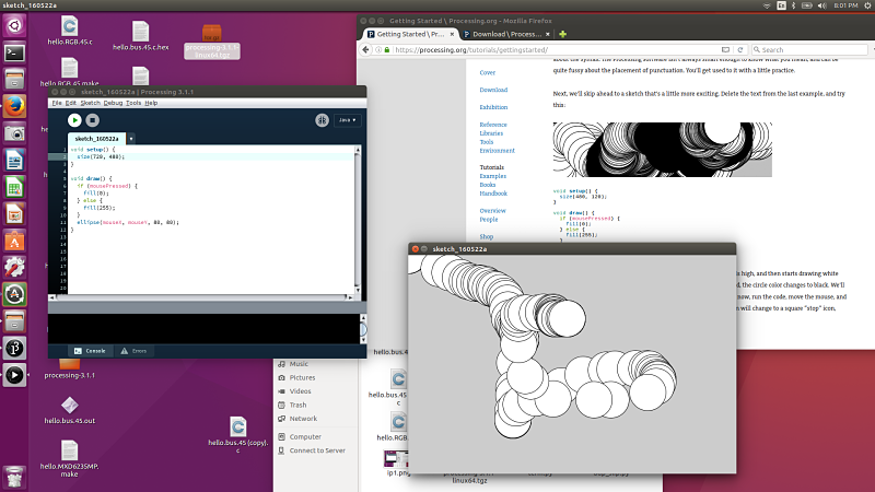
I then decided I needed to start the process of having my board interact with a program written in Processing. I looked at the Fab Academy Processing tutorial and downloaded the simple serial stub. This is the format that allows me to communicate through my FTDI header into the correct serial port. I used this file as the basis for what I wanted to accomplish visually. I then looked at the reference files and tutorials and started to build my code to get my shapes I wanted to display and change with the phototransitor. I found the reference page useful as I tried to figure out how to get the correct code. I spent several hours working through examples trying to figure out exactly what was needed to program my board to interact with the phototransitor.
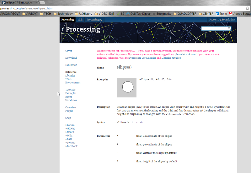
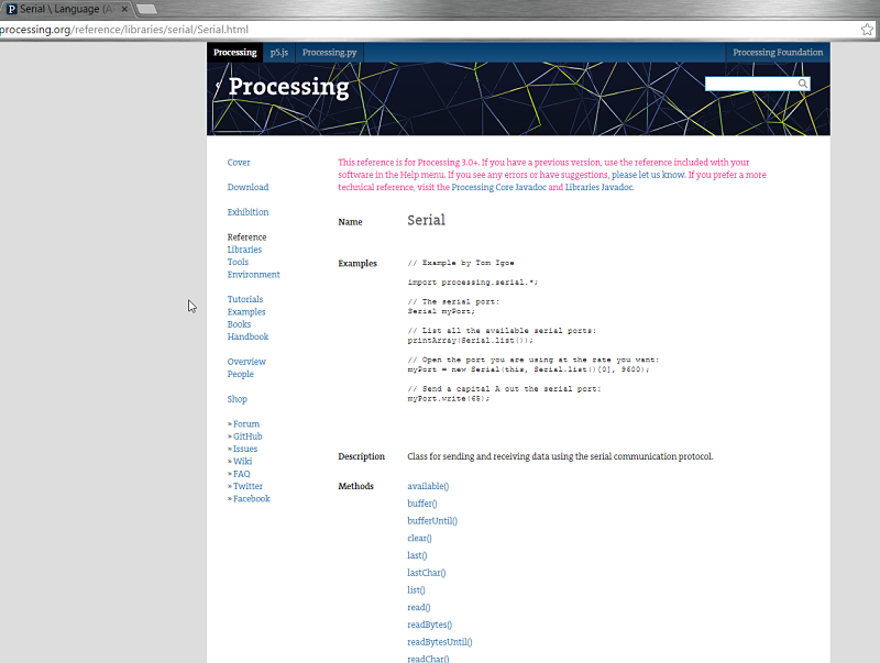
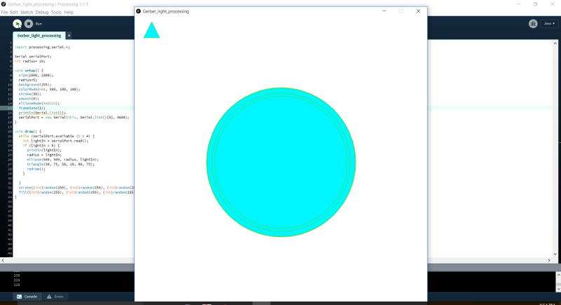
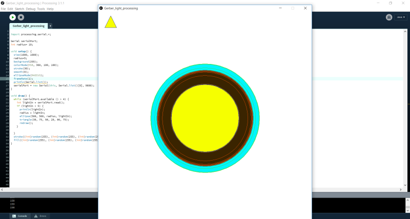
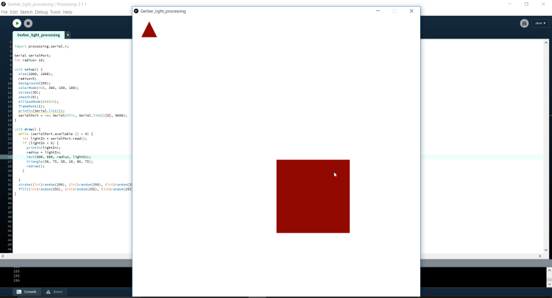
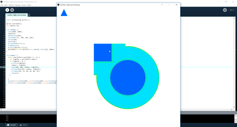
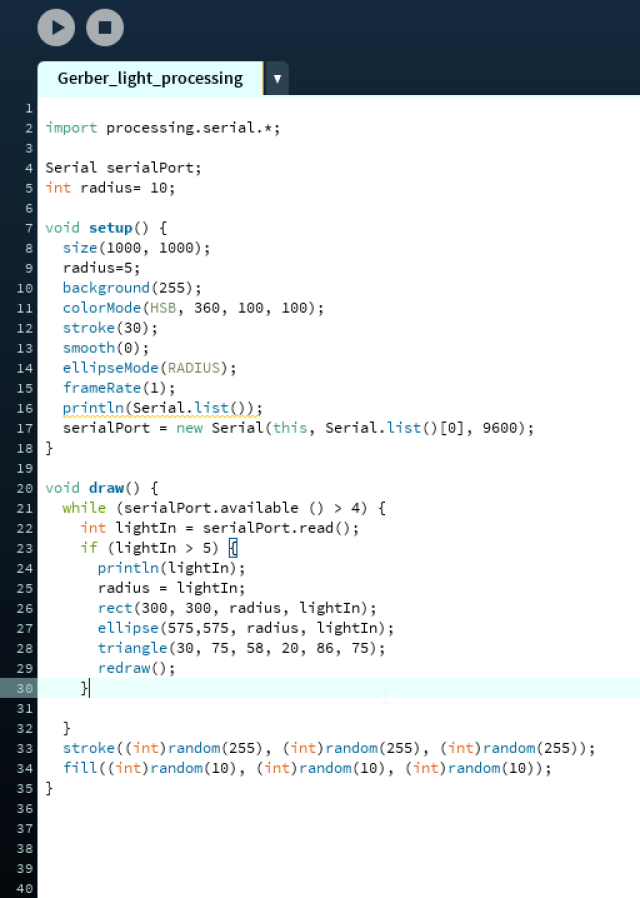
I then started by working through the sketch. I added the Setup portion of the sketch. This included stroke, size, radius, background, smooth, colormode, serial port and lightIn information to set up the sketch. I refered to the Processing Reference page for most of this to make sure it was correct. I then progressed to the Draw portion of the sketch. This defined the interaction between the serial port and phototransitor and what it would draw if it was within the parameter of the light input. This portion took awhile to figure out as I looked as sketches and examples similar to this in the tutorials section and reference section of the Processing website. I finally got it to work and then started to adjust the different shapes. I started with the ellipse I used in my first tutorial and then added the rectangle and triangle. It worked as is should and as I covered the phototransitor it went to a solid color and when it was less than 5 it randomly generated colors in the ellipse, rectangle and triangle. I did noticed the response time seemed slowed between my interference with the sensor and what is displayed visually. I did try to play with the sample rate in the frame rate of the code. This did not have the immediate impact to make it more smooth and the delay was still present.


Project Files: