(Make something big (on a CNC machine).
In the seventh week we will use our CAD skills to design and make something big. What exactly is the size of something big. Bigger than your head? Bigger than a car or house? I decided to make a rolling cart for the Full Spectrum laser in "Grandpa's FABlab" I mentioned in my bio that I am creating a FABlab in my basement for my grandchildren to learn creativity. I am trying to make as many components/machines for my FABacademy projects that can do double duty in "Grandpa's FABlab".
Part of the process this week is to document the design and workflow needed to make the project.
The tasks for Week #7 are to;
We have a good selection of materials on hand at LCCC. I figured that the laser cart would get quite a lot of abuse so I decided to make it out 3/4" MDO. The MDO sheets I used have a paper side and a roughside. The paper can face out and the rough side can face in. I did the designing in AutoCAD because I am more comfortable with it.
First I created a cad drawing of all the components that needed to go in the cabinet. Not counting the laser itself, I needed to have room for a fume extractor, water bucket and pump and a small air compressor. If possible I would like to have some room left over to store some materials for the laser.
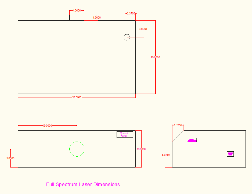
Here is a drawing of the laser itself.
Here are all the components needed for the operation of the laser.

As I went through the design process I found that my ideal dimension would not efficiently utilize the 4' by 8' plywood panels.
I shrunk down the size of the cart to create the longest dimension out of the 4' width of the panel. I ended up with a lot less scrap marterial.
As part of the design process I needed to calculate the allowances needed to match the cad drawings to the machining process. I created a test joint to check on those allowances. My tenon measured 3/4" by 4". Making a part to that dimension was too tight. I measured the part and decided that I would need to add .020" to the length and .010" to the width. .760" by 4.020"
Here are the final sizes of the test joint.

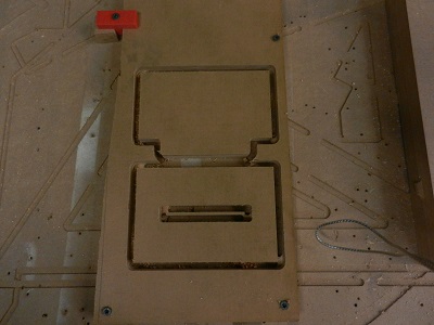
Here are the parts cutout for the test joint.
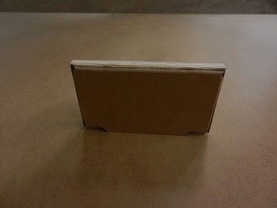
Here is the test joint assembled.

Here is a verification that the test joint will work in the final machining process.
As you may have guessed by now I am using a Shopbot to machine my parts. We have a 4' by 8' PRS Standard Shopbot. It has served us well forquite some time.
Here is a picture of the Shopbot in our lab.
I used Aspire 8.0 CAM software to create the files for the Shopbot. We used to use Partworks software and it served us well for a numbe of years. The switch to Aspire allowed us to have more features and choices in programming. It also allowed us to create files for our full-size Haas machining center. Much easier for the students to learn one CAM package. I created many cam files in the production of the laser cart. In case I ran into problems I did not want to ruin too much material.
Here is a screen shot of the front and back of the cart shown in Aspire.

I machined the parts in batches as I designed them. As the parts machined started to come together, I grew more comfortable with the software and the design process. I would machine a few parts to make sure they were alright and then design the next couple. My design method was to use the original drawing of the front of the cart to then design the back. After the back was made i designed the top and bottom. I would just extend lines from the current drawing to insure that all parts were the same size and matched their counterparts in the other drawings. This method work out very well as I was dsigning and verifying all at the same time. I would cut one part out of a 4' by 8' sheet, verify it was okay then create a new cad file for the next part. This may seem like a lot of work but I did not have any rejected parts. If I were to just design all the parts and cut them I may have created nothing but a big pile of scrap wood if they did not match. I used Neil's method of working on small pieces of the problem at a time. Any errors would then not be too costly.
I used a 5/16" flat endmill to cutout the parts. I could then use a 1/4" flush trim bit to remove the tabs leftover from the machining process.
5/16" flat endmill RPM=13,000, Pass depth = 0.265 ", stepover = 0.125", Feed rate = 1.5 "/sec, Plunge rate = 1.0 "/sec.
1/4" flush trim bit RPM = 8,000, operated by hand.
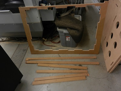
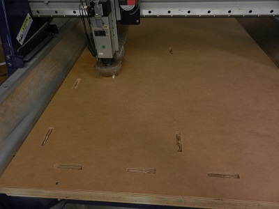
Here is a picture of the Shopbot cutting out the front, back and top pieces of the laser cart. You may notice that I cut the doors out of the same material as the front. Less material waste that way. There may be a gap in the doors, but I need the ventilation to keep the cabinet cool.

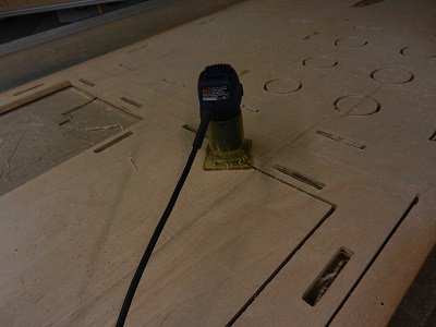
In this picture you see a trim router used to separate the parts from the waste. I used a 5/16" endmill to cut out the parts leaving tabs to keep them in place.
I then used a 1/4" flushtrim bit to remove the tabs.
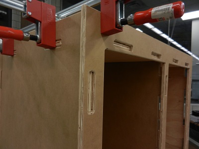
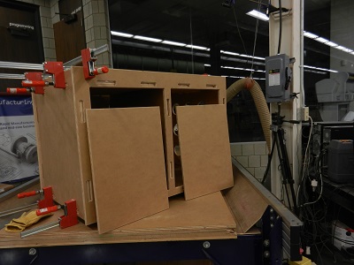
The assembly seemed to go well. I test fit the parts together using some large Bessey clamps. The joints all lined up but were a little snug. I almost think I can put the cart together as a press fit but I need to be able to transport the cart.
The first few seemed to line up very well.

Adding the sides and a few clamps helps guide the joints.
Here you can see the back and the left side with ventilation holes.
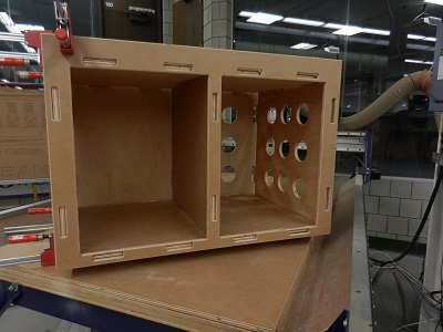
And last you can see the parts in their relative final positions. I will add hinges and put a clear coat of urethane on the cart when I get it home. The cart will be mobile by use of 5" full swivel and locking casters.
The verbage and graphics presented so far should be enough to show what I did.
Some of the problems I enountered were;
Designing one part at a time from the previous part seemed to eliminate bad parts.
Creating and fitting a test joint piece minimized trouble in joint fit up.
Shrinking the size of the cart and cutting the doors from the scrap saved a lot of material.
I verified and tested all feeds and speeds used by the Aspire software. One problem I have encountered when using a shopbot or other CNC router is the lack of information on speeds and feeds. As a machinist I want to know what cutting speed is required for different material. I will then use my own formulas to calculate RPM and FEEDRATE.
The last problem I ran into quite frequently. For some reason
Aspire, AutoCAD and Kompozer
would have problems and I would lose all work since the last time I
saved.
It took me back to my time using a main frame to program Apt and
Compact files.
Type, type, save. Type, type, save. Type, type, save. Type, type,
save.
.....