Tim Bruening - Fab Academy 2016
Week #4 - Electronics Production
In the fourth week we explored Electronics production.
Most
pieces of high tech equipment have some sort of circuit board in them.
They monitor the inputs of a system and acting on a
predetermined
set of rules cause outputs to happen. Using printed circuit
boards (PCBs) we can control almost anything. During this
week we
will make our own PCB and program it to program the other boards we
will need for our projects.
Here is a list of tasks as I see them for the fourth week.
Use FAB modules to create the traces for a PCB.
Use FAB modules to cut out the outline of the PCB.
Practice soldering.
Solder the PCB ( I used Zaerc's example).
Program the PCB
Test the PCB.
Document the process and list any problems encountered.
Use FAB modules to create the traces for a PCB.
I used a Roland Modela MDX-15 milling machine.
- Login to Ubuntu
- Start FAB server
- Start terminal
- Type mod_serve &
- Leave terminal open
- Start Firefox
- Goto FAB modules URL
- Left click on input format
- Select load settings
- Image (.PNG)
- Select "fabTinystar-012_top.PNG"
- Select output format
- Select process
- PCB traces (1/64"0)

- Left click on calculate
- offsets = -1
- tool diameter = 0.3
- Cover entire back surface of PCB with double sided tape
- Place on front left corner of sacrificial board
- Change to 1/64" tool
- make tool very short (push into spindle)
- Press "View" on Modela
- Set "Z" zero location
- Manually move down to part
- Loosen tool (hold it) then set it on the top of the part
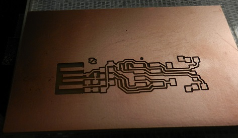
- Click "Send" in FAB modules
- Mill cuts the part traces.
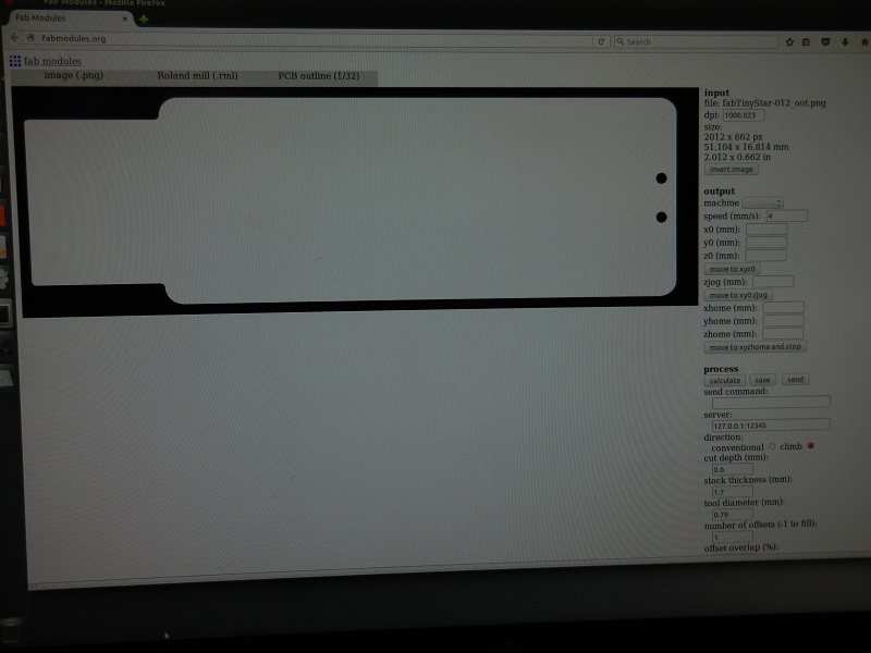
Use FAB modules to create the outline for a PCB.
Repeat steps to cut the outline of the PCB board.
Use file "fabTinystar-012_outline.jpg"
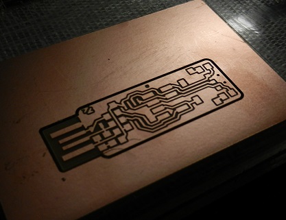
Clean circuit board with alcohol and brush.
Proceed with populating the board.
Practice soldering.
Next comes the task of populating the board with electronic
components. The first thing I did was to practice my
soldering technique. We used practice kits laid out in the
lab for us.

Solder the PCB.
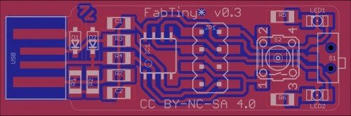
After some practice I felt that I could tackle the soldering
of the PCB board. We were given a picture showing the
placement and types of components needed for our circuit. We
organized all our parts by taping them down on a sheet of paper.
That should keep them from getting misplaced.

Here is a picture of the half completed PCB.
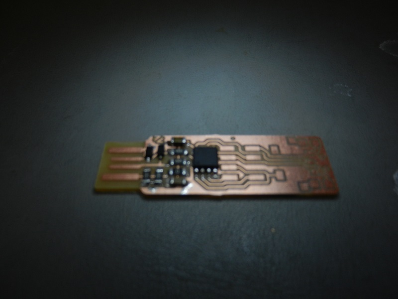
Here is a picture of the completed part.

Program the PCB.
Using the information from Zaerc's website we porogrammed our
new PCBs.
sudo apt-get install avrdude
sudo apt-get install gcc-avr
make -f hello.ftdi.44 echo.c.make
sudo make -f hello.ftdi.44.echo.c.make.program-usbtiny-fuses
sudo make -f ello.ftdi.44.echo.c.make program-usbtiny
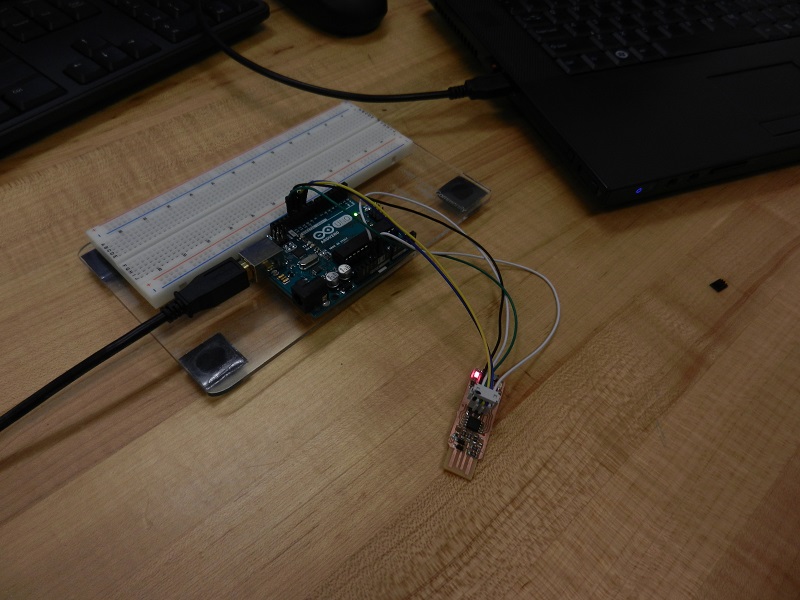
Test the PCB.
Here is a picture of the board test.

Document the process and list any problems encountered.
My documentation pretty much speaks for itself. As
far as problems I found that I needed to helped quite a bit along the
way. I am still a little fuzzy as to what exactly happened
when we programmed our PCB boards. I assue that we will get
further incite into the process as the class progresses.
Back
to index