
Unfortunately, because of my lack of knowledge of programming, I was only able to use c-programming.
The first thing needed was to find out what pin on the AtTiny44 is tied to the LED and Resistor 2 (PB2) and what pin on the AtTiny44 is tied to Switch 1 (PA7). I had to look at the original design for the board and my schematic back from week six.
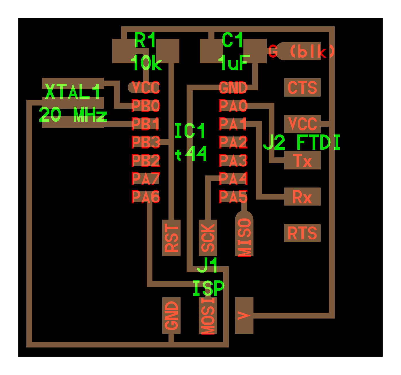
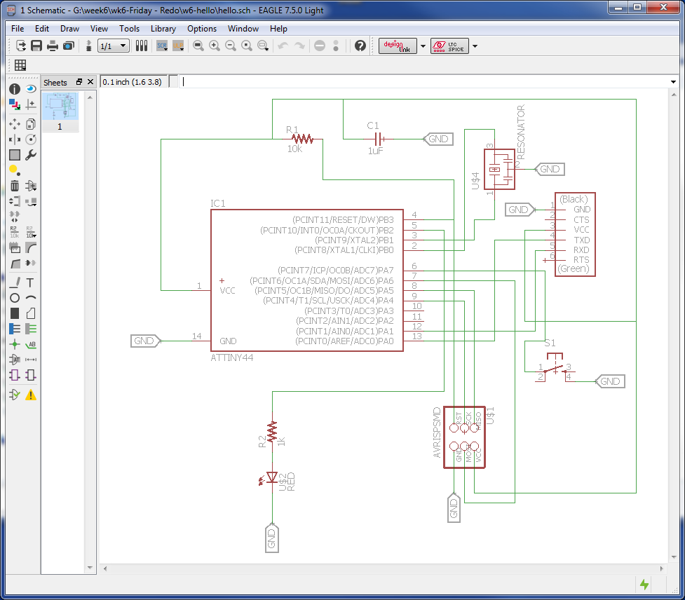
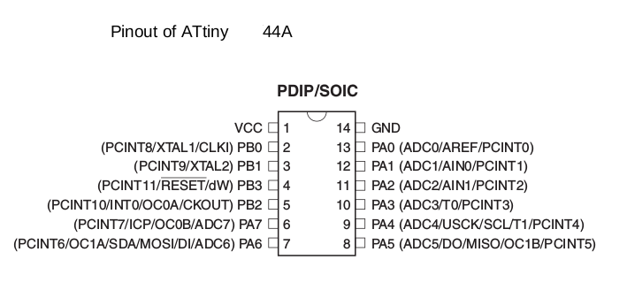
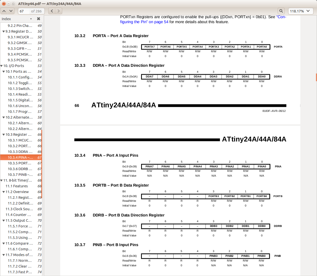
The images below show the Pinout of the ATtiny and the Data Registers and Data Direction Registers for Ports A and B. (PA pins are Port A, and PB pins are Port B).
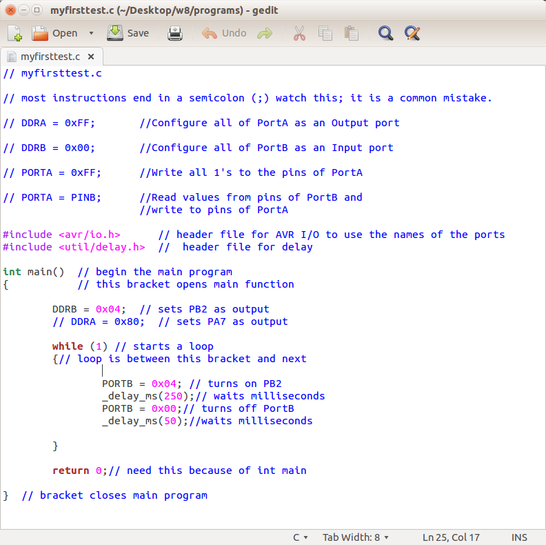
Write a C program: Write the C program using a text editor and give it a name "myfirsttest.c". I added plenty of comments before the actual program and after most of the code for my future reference. I had to confugure PB2 as an output port for the LED and then begin a never ending loop. The instructions within the loop turn on PB2 for 250ms and off for 50ms.
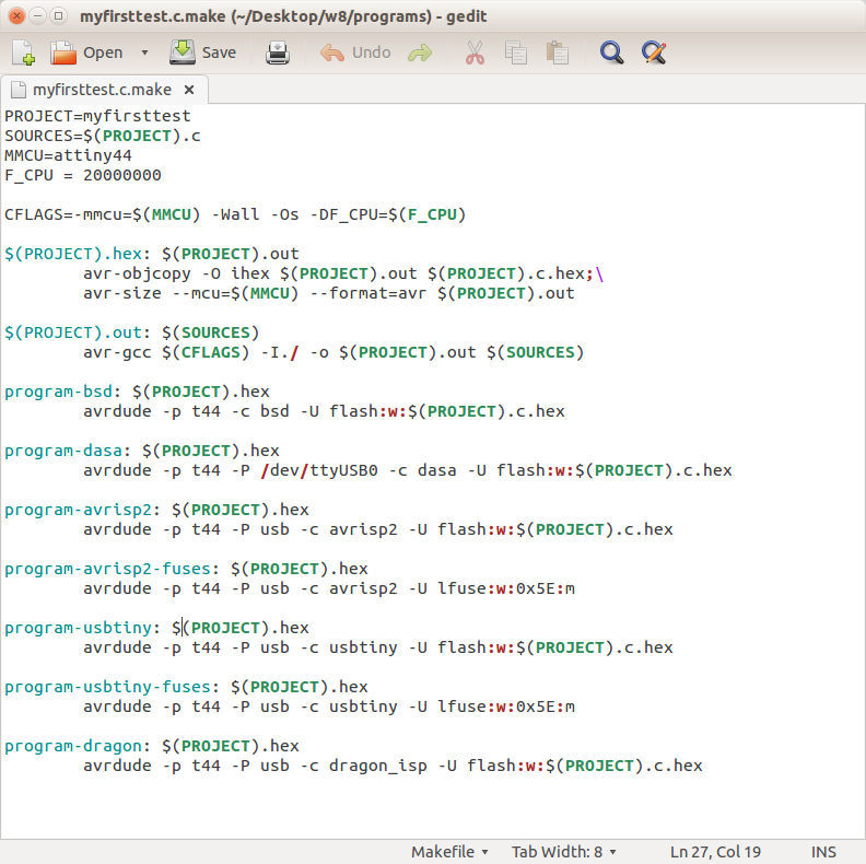
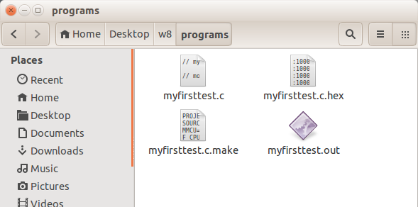
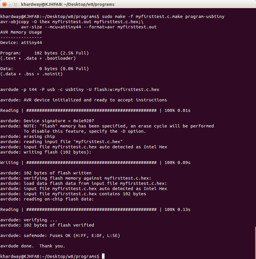
Compile myfirsttest.c: I modified this Makefile, changed the name to "myfirsttest.c.make". On the first line of the script, changed PROJECT = "myfirsttest". In a terminal window, type, "make -f myfirsttest.c.make". This creates myfirsttest.c.hex and myfirsttext.out.
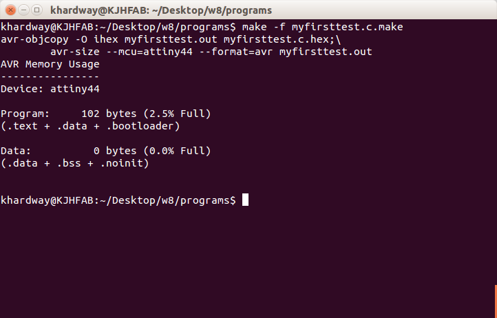
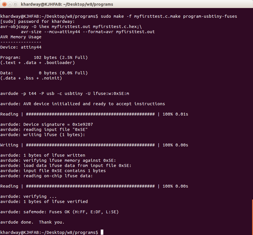
Run two more parts of the Makefile: This step was shown in the Programming on Fab's web page. The original file name has been altered to reflect my project this week.
First step completed ..... now on to the Pushbutton
Worked a few hours trying to configure this push button ....No luck at all ....... looks like I will have to consult the GURU.
Stay tuned.
Follow steps above with a new program "kbutton.c":
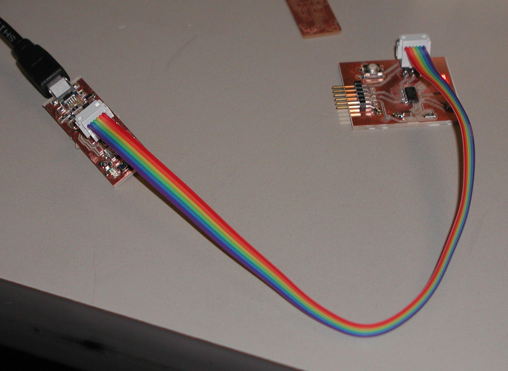
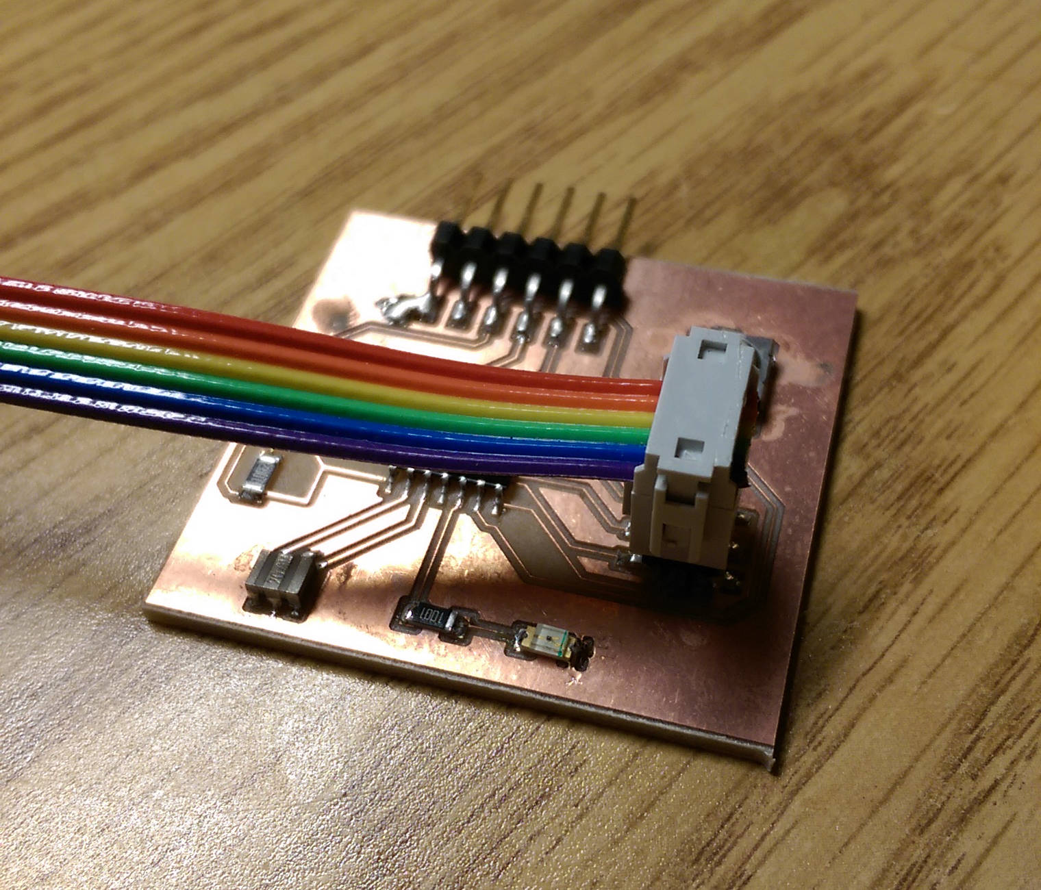
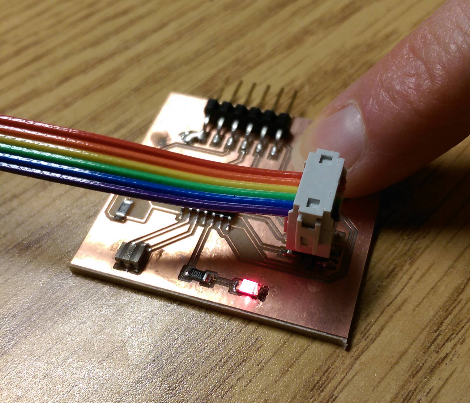
Debugging programs is very difficult with little or no clue of c programming language or circuit design, or soldering, for that matter. I did not know if the problem was with my push button on the circuit or with my program. Thanks again Chris for your assistance! The issue was not with the pushbutton. Below is the image with the button off and then depressed.
Blinking Programming Files
Pushbutton Files