
This week we were given the assignment to make something big.
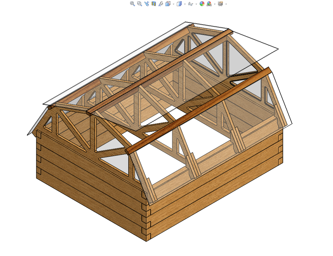
This is the week I decided to begin the construction of my final project; which is a seed-sprouting green house. The final design looks quite a bit different from the original idea at the beginning of this class.
Hardware, software and material list:
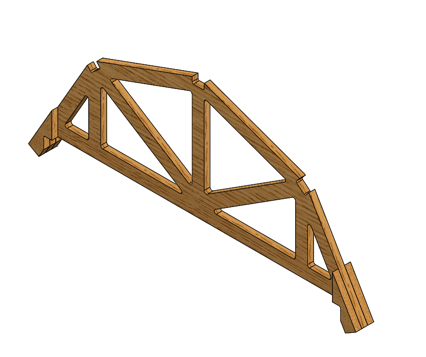
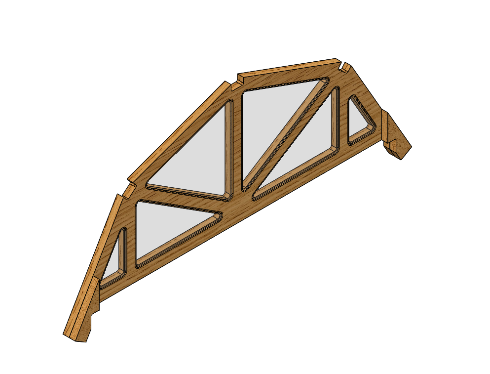
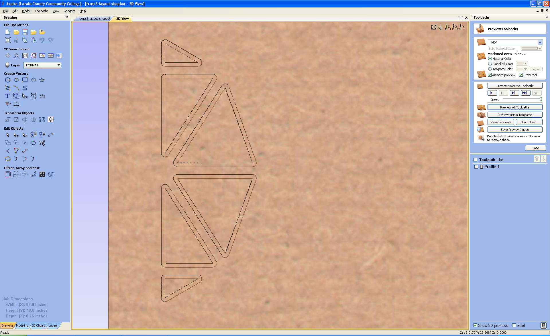
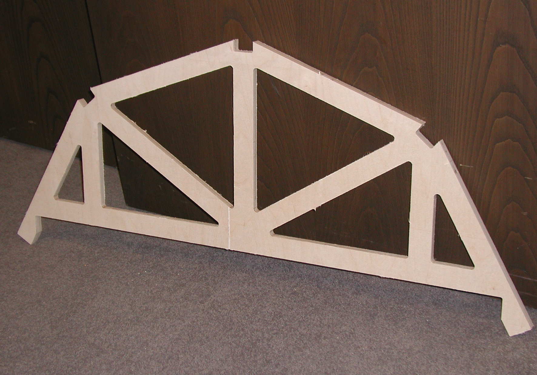
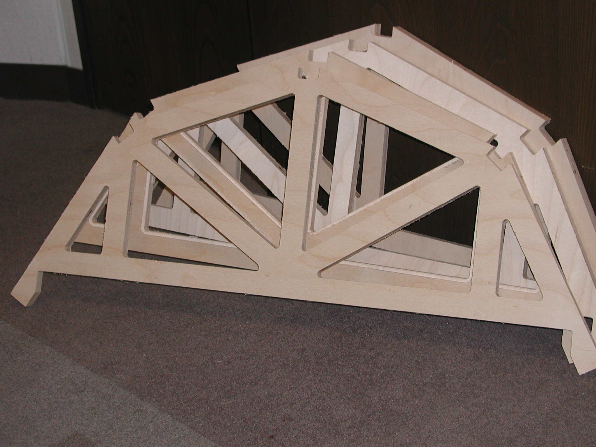
The first two images below are what I plan to cut this week from the Shopbot. I also plan on adding plexiglass windows to the exterior trusses. Two of the trusses will require a 1/4" wide by 3/16" deep pocket for the windows. The windows will be flush with the inside face of the trusses. The third image, one truss and side support, will be imported into Aspire as a DXF format. There are a total of four trusses to be cut; two for the exterior and two for the interior. There are a total of 12 supports that will be cut. The fourth image below shows the final design with a hinged, plexiglass roof.
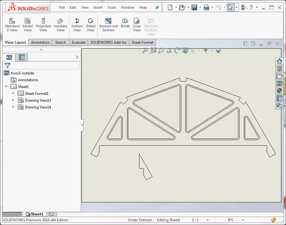
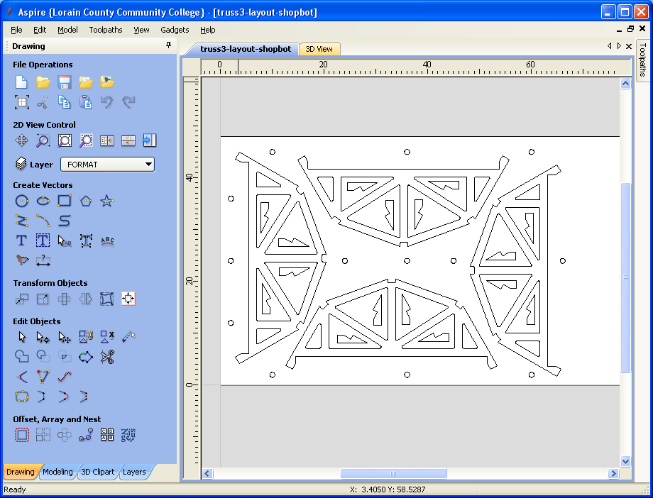
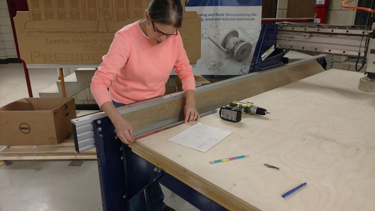
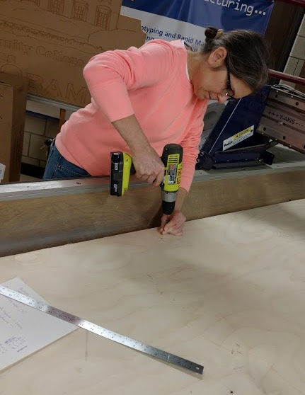
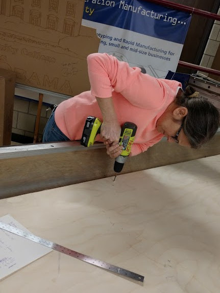
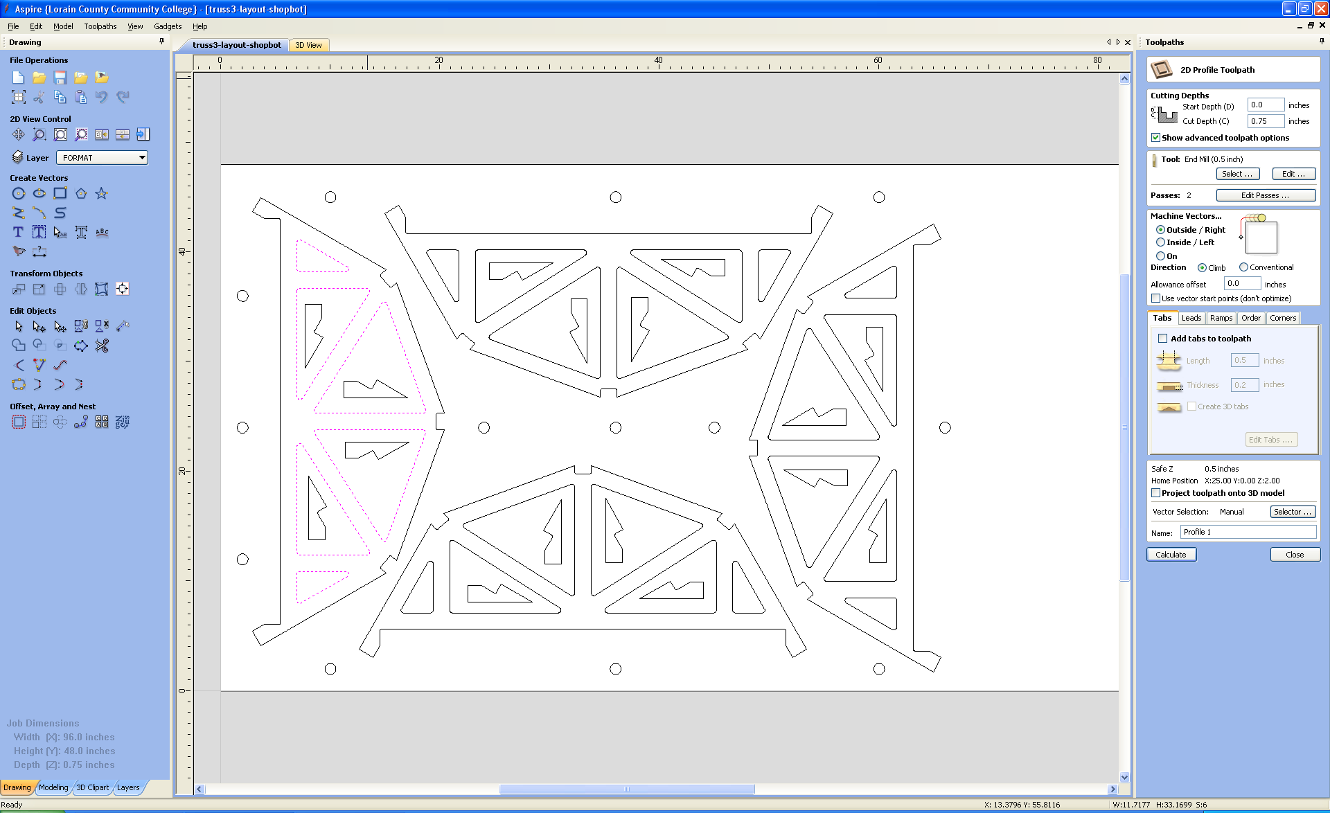
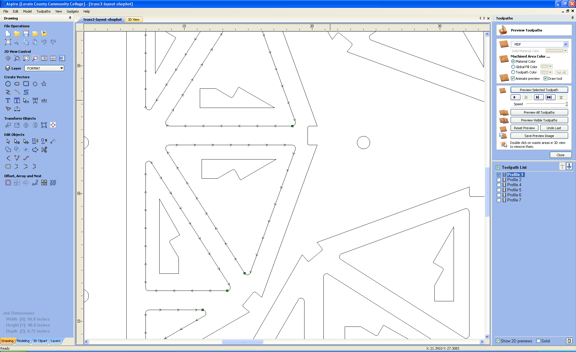
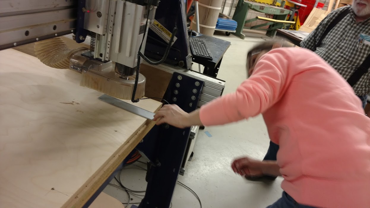
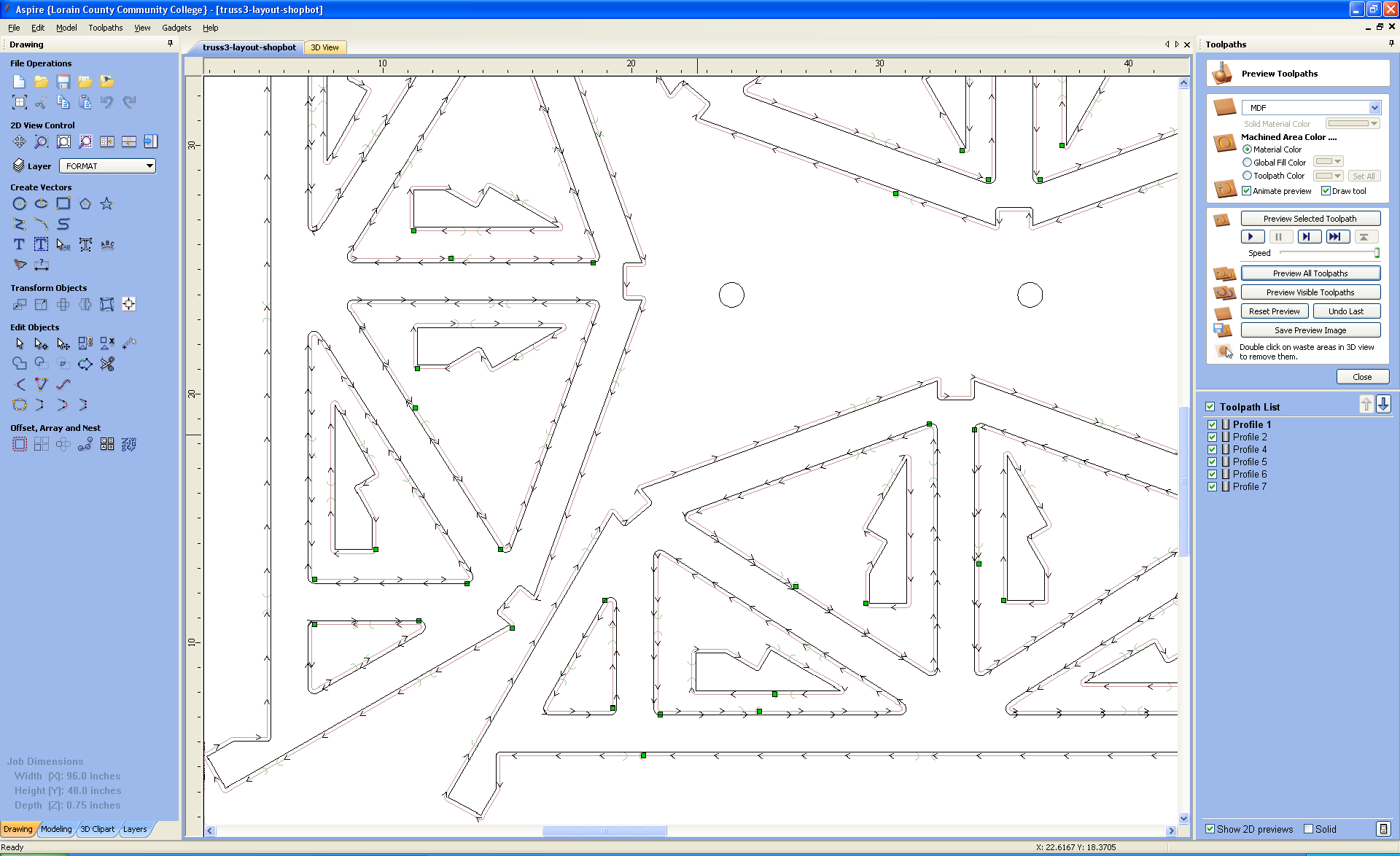
Locate where to secure the plywood to the bed of the Shopbot: The DXF files are imported into Aspire. Below is the layout of the four trusses and 12 (actually 16) supports in Aspire. The trusses are on a 4' x 8' sheet of plywood. I added circles on the image below to get a dimension from the origin of the machine for the X and Y locations ofr the screws. The screws are used to hold the plywood to the sacrificial layer on Shopbot. Before leaning across to secure the plywood with screws, make sure you wear an apron, or lay something across the side of the CNC machine. You will get greasy if you don't.
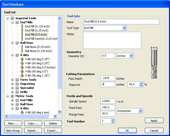
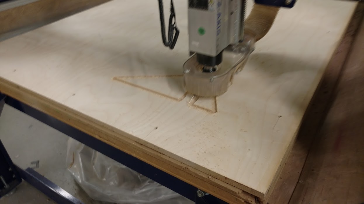
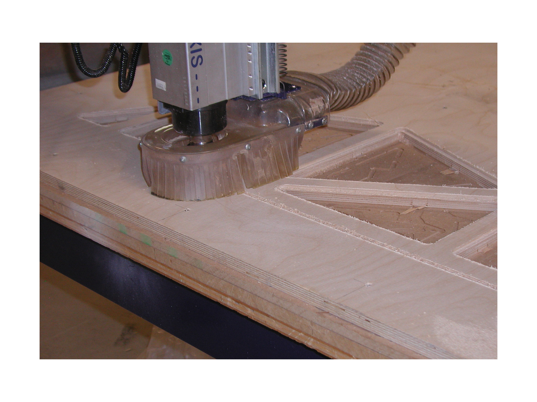
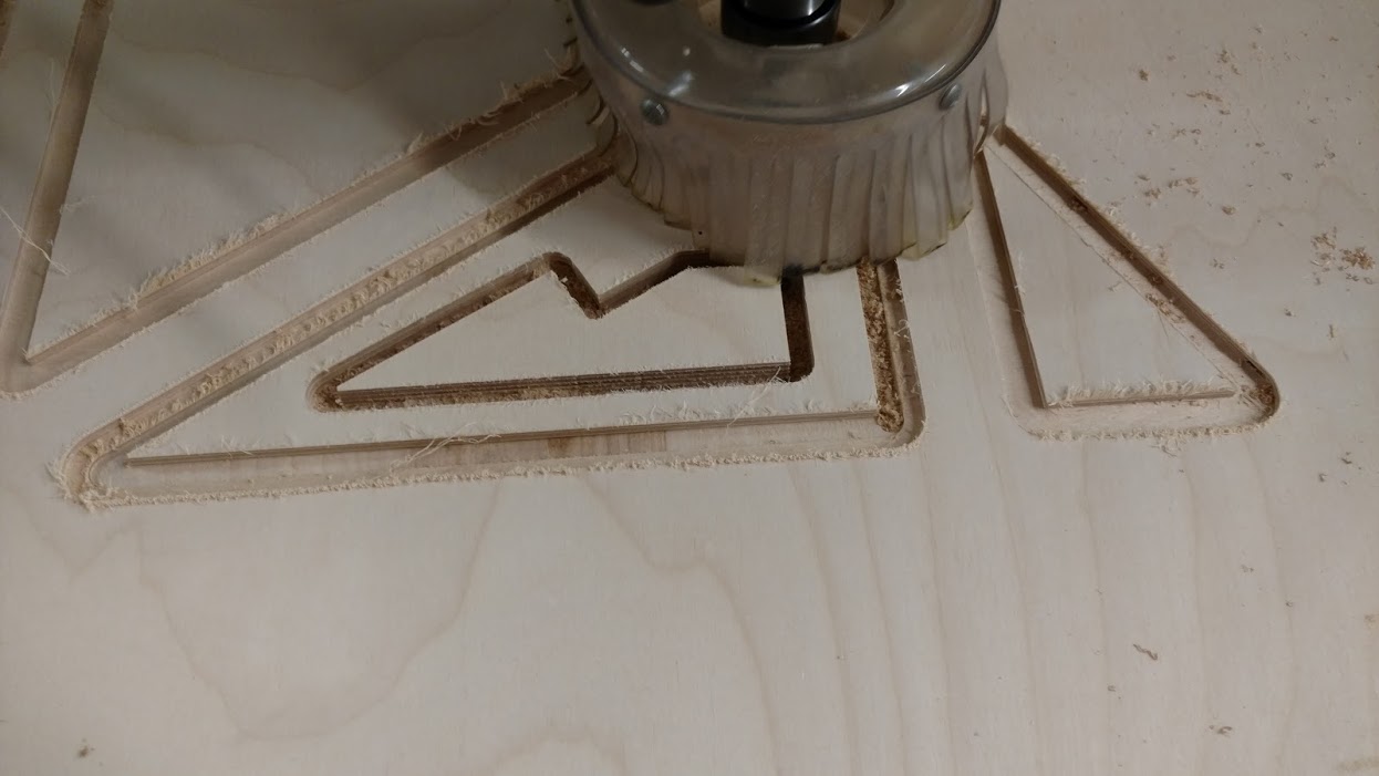
Create the tools: I used a 1/2" and a 5/16" end mill. The feeds and speeds, and cutting parameters are set on these tools. The 1/2" endmill is used for cutting the .1875 (3/16") pocket for the windows and are cut on the vectors as shown below. Cutting with a 1/2" end mill on the vector will ensure a quarter-inch on each side of the window area.
Set up the first cutting paths for the window cuts: The first cuts to make into the plywood should be the cuts that are not through cuts. In my case that meant cutting the window pockets. and setting the tool to cut on the selected vectors. The vectors are to be JOINED, not GROUPED. Joined vectors create a dashed line instead of a solid line when they are selected. Make sure to preview the tool path.
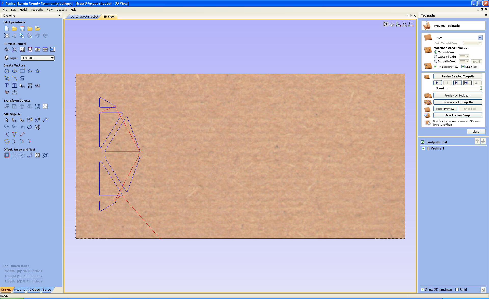
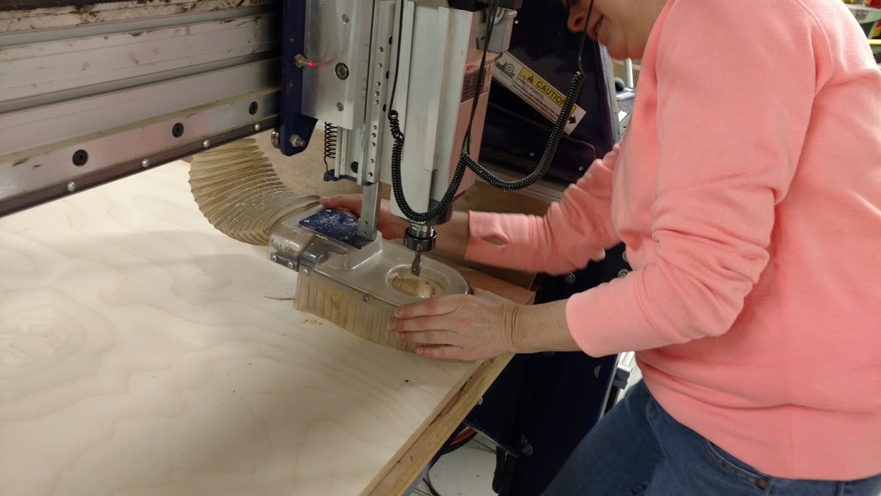
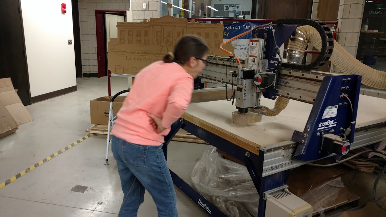
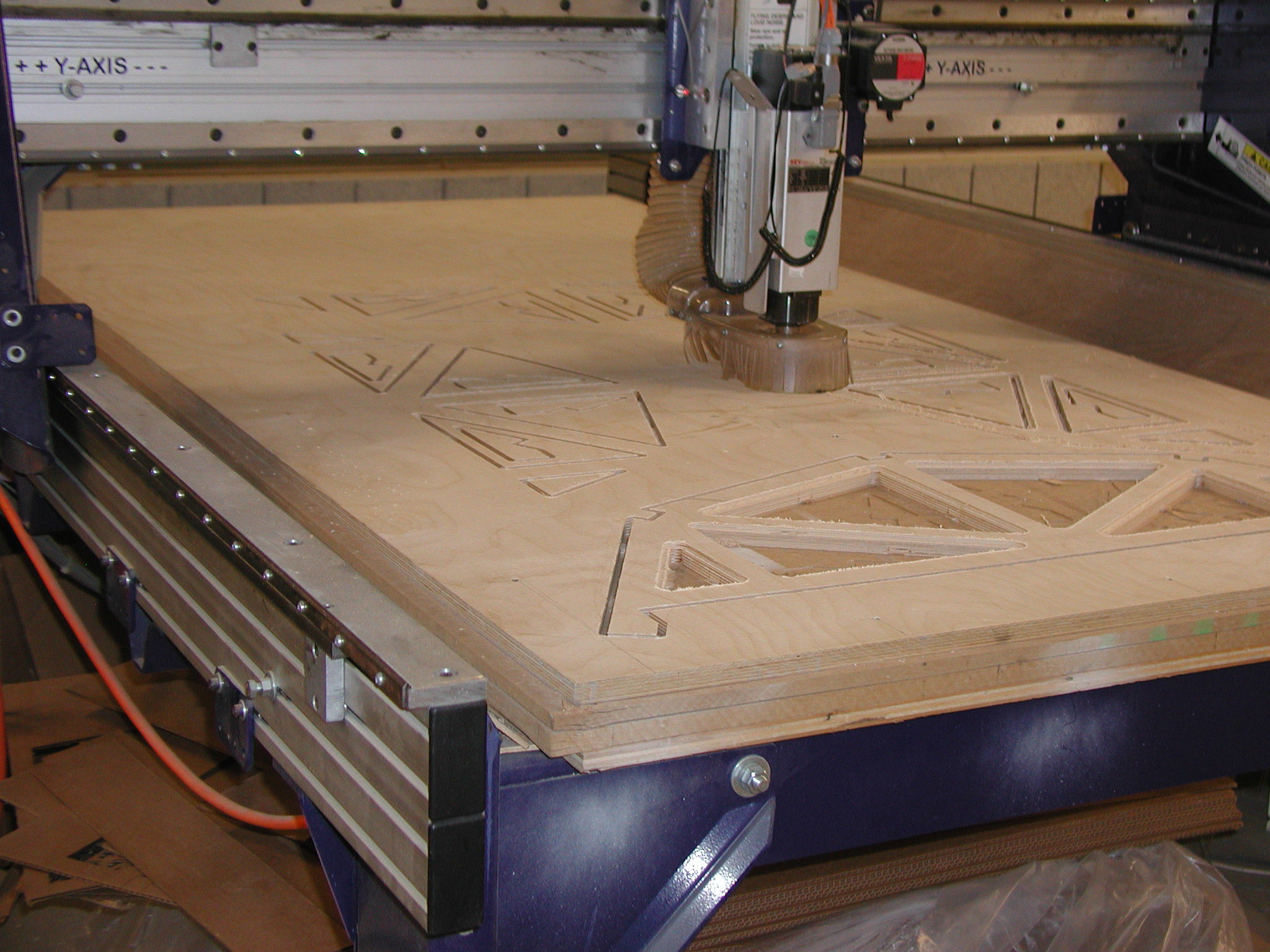
Set up the Shopbot: The existing tool was changed in the Shopbot, the machine was zeroed on the X, Y, and Z axis. The Z-axis was set at one inch above the plywood so one pass could be run as a trial. The spindle speed set to 12,000 rpm. When the trial was complete the Z-axis was brought to the plywood the the cutting began. The first cut was the 1/2" endmill on the vector of the windows. See see images of the setup and cuts below.
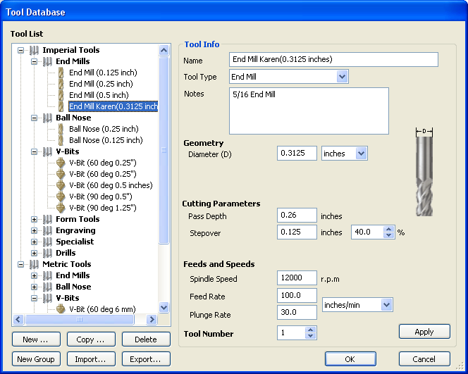
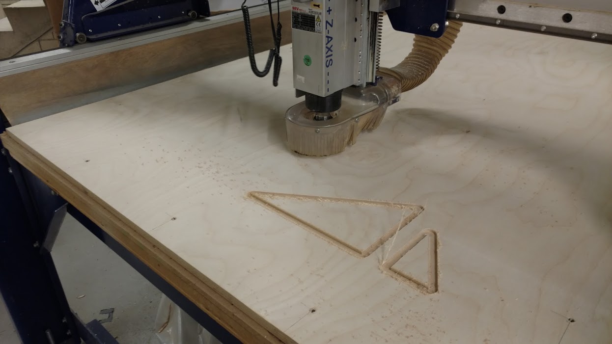
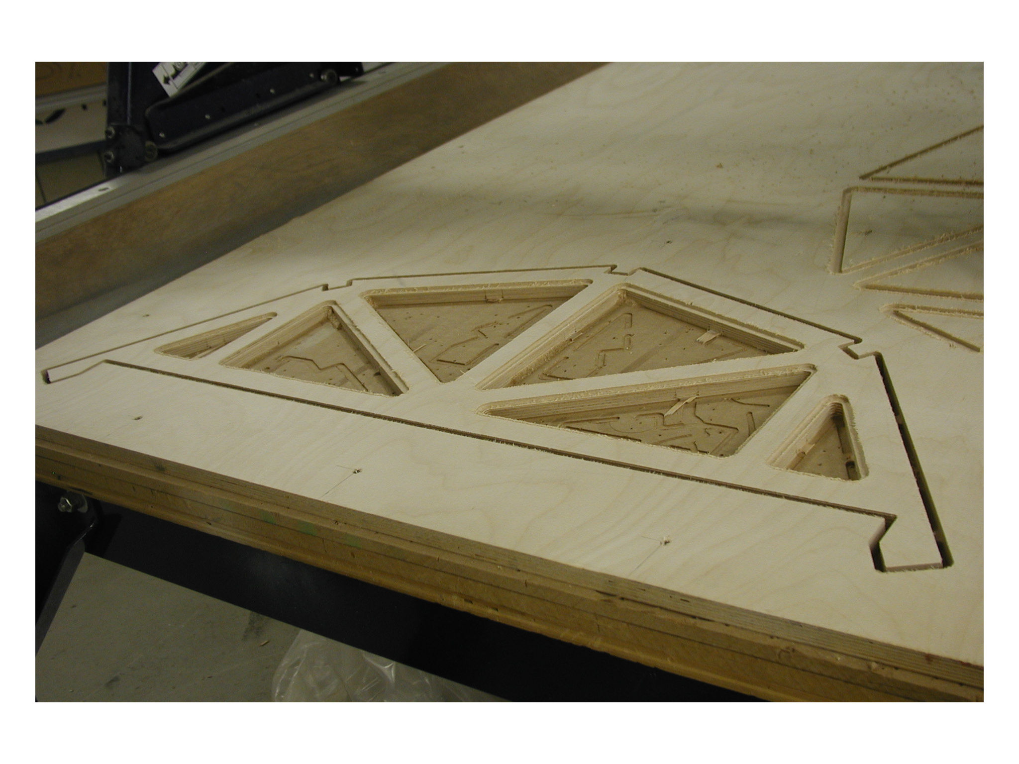
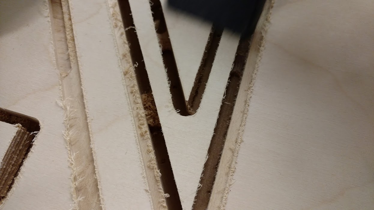
Create the through cut profiles: I used a 5/16" end mill for all through-cuts. The feeds and speeds, and cutting parameters were defined when the tool was edited. The Some of the vector cuts are on the inside of the vectors and some of the cuts are defined on the outside of the vectors. Be careful with nested vectors as I have on my layout.
Set up the first cutting paths for the theough-cuts: The 5/16" endmill is set to pass three times. The final cutting depth will be 0.78 inches to make sure the three passes (.26 inches times three passes) of the tool cut through the plywood into the sacrificial layer. The plywood is 0.75 inches thick. One truss was completely cut before the final three. I also added 1/8" thick tabs that were 1/2" long so the part would not fly out when the through cut was completed. I found the thickness of the tabs to be too thin because the pieces were able to be manually removed when each cut was complete. I used 1/4" tabs on the final three trusses.
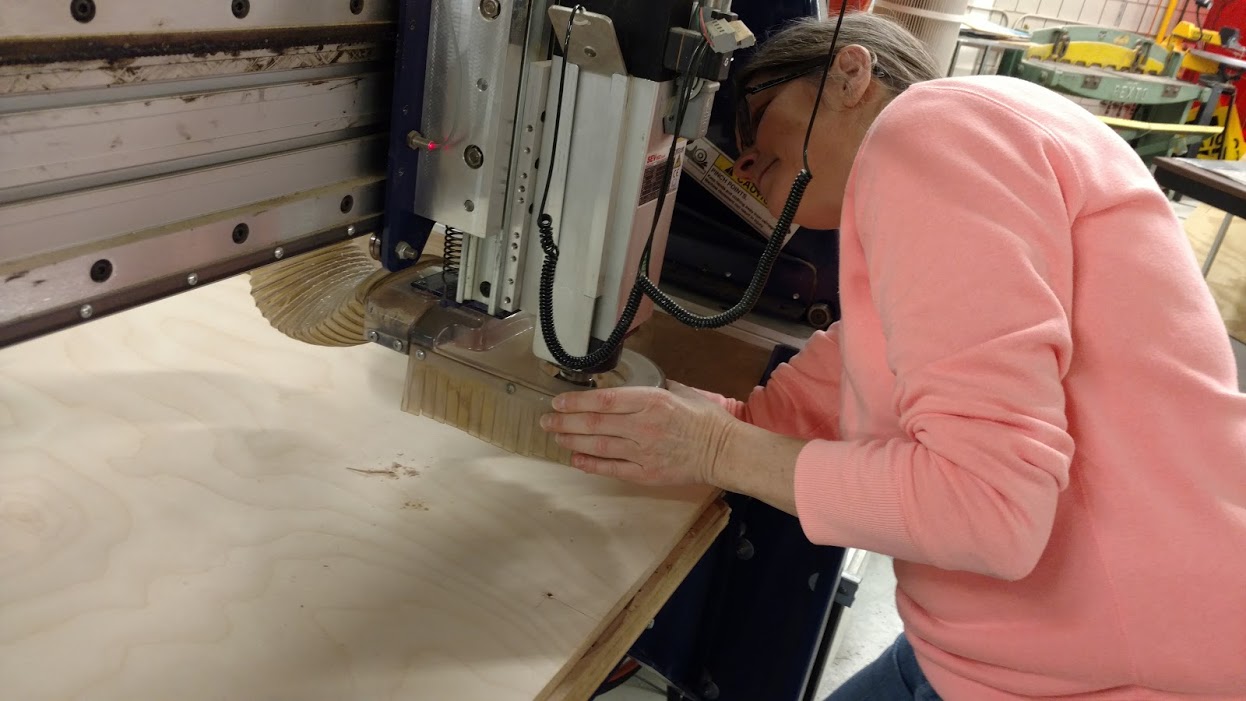
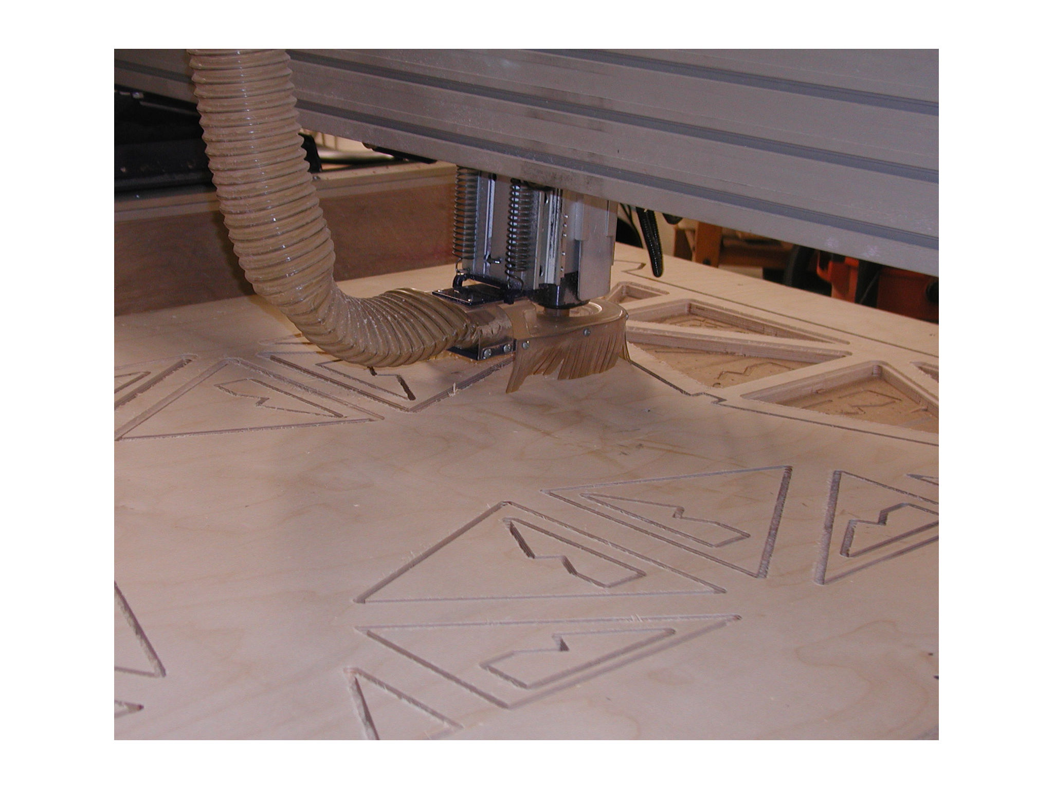
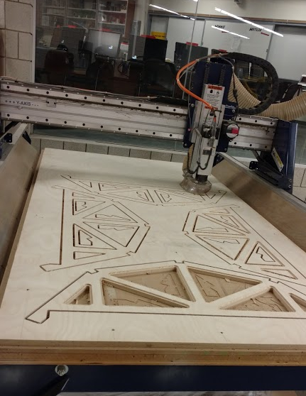
Set up the Shopbot with the 5/16" endmill: The existing tool was changed in the Shopbot, the machine was re-zeroed on the X, Y, and Z axis. The spindle speed remained set to 12,000 rpm. No trial was used during this run. See see images of the cuts below. Notice on the second image below the number of profiles that were actually used. Profile 1 was the first 3/16" window cut. Profile 2 was the second 3/16" window cut. Both Profile 1 and 2 were cut on the vector on two trusses only. Profile 4, 5, 6, and 7 were the through cuts. Notice some profile cuts are on the inside of the vectors and some are on the outside of the vector selection.
Solidworks Files
DXF files