
This week we were given the assignment to redraw the Echo Hello-World board with the addition of a button, LED, and 1k resistor on the schematic. After the schematic is designed we are to make the board and populate it with the proper components.
This is the first time I have ever done any board design or used any board design software. It took quite a while and many attempts to get a the completed assignment done for this week. I tried to design the board from the image in the link above as best as possible and I worked along with the following two tutorials on You-Tube. Following along with this tutorial allowed me to complete my board design.
Tutorials by Jeremy Blum
Software Used to create this board:
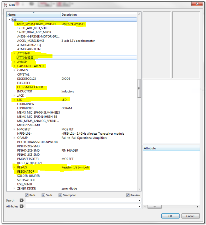
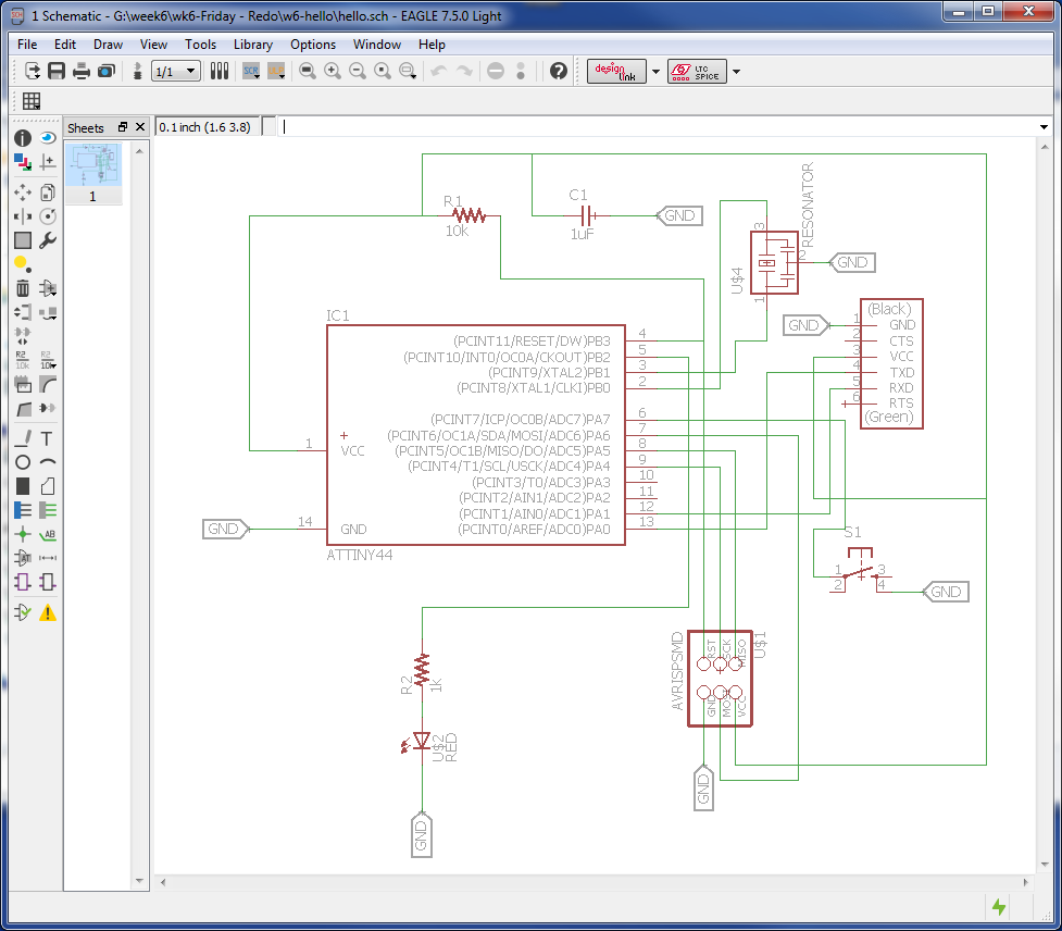
EAGLE was downloaded from the above link and installed. The FAB library (fab.lbr) was copied to the library folder within EAGLE. A new project was opened and a new schematic was started. The first step is to insert all of the proper components into the new schematic. The highlighted components below were the selections used.
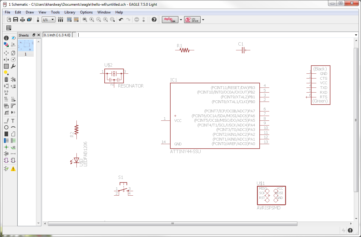
All components added into the schematic.
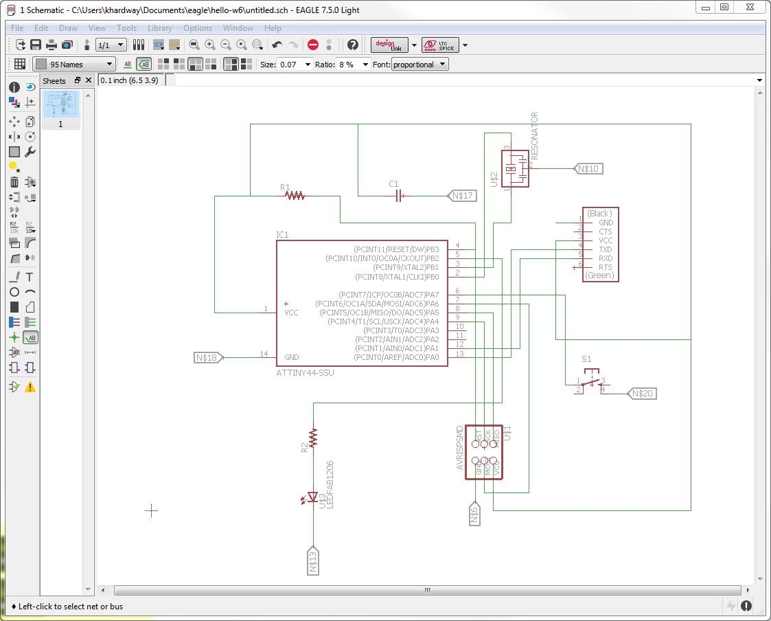
A wire is added between mating components. Select "Wire" from the Draw menu or make the selection from the left pane icons. Another option instead of adding a wire between connecting components, is to add a small length of "wire" and "label" and then give the label a "name". Wires with the same name are connected in the schematic You can choose to label and name all wires, or just a few as shown below.
The labels added below are named "GND", and all will be connected to the point of ground. Make sure all are labeled properly. You may notice that two labels were missed and still have the default names. After the board was made I had two components not attached on the ground plane and had to be jumpered to get there. Notice the capacitor (C1) and the ground pin on the header; both still have their original labels. Looking at the completed board at the end of this page, you can see the two extra large pieces of solder that were required to make the jump to the ground plane. Thank you Chris for that catch and showing me how to fix it!!!!!
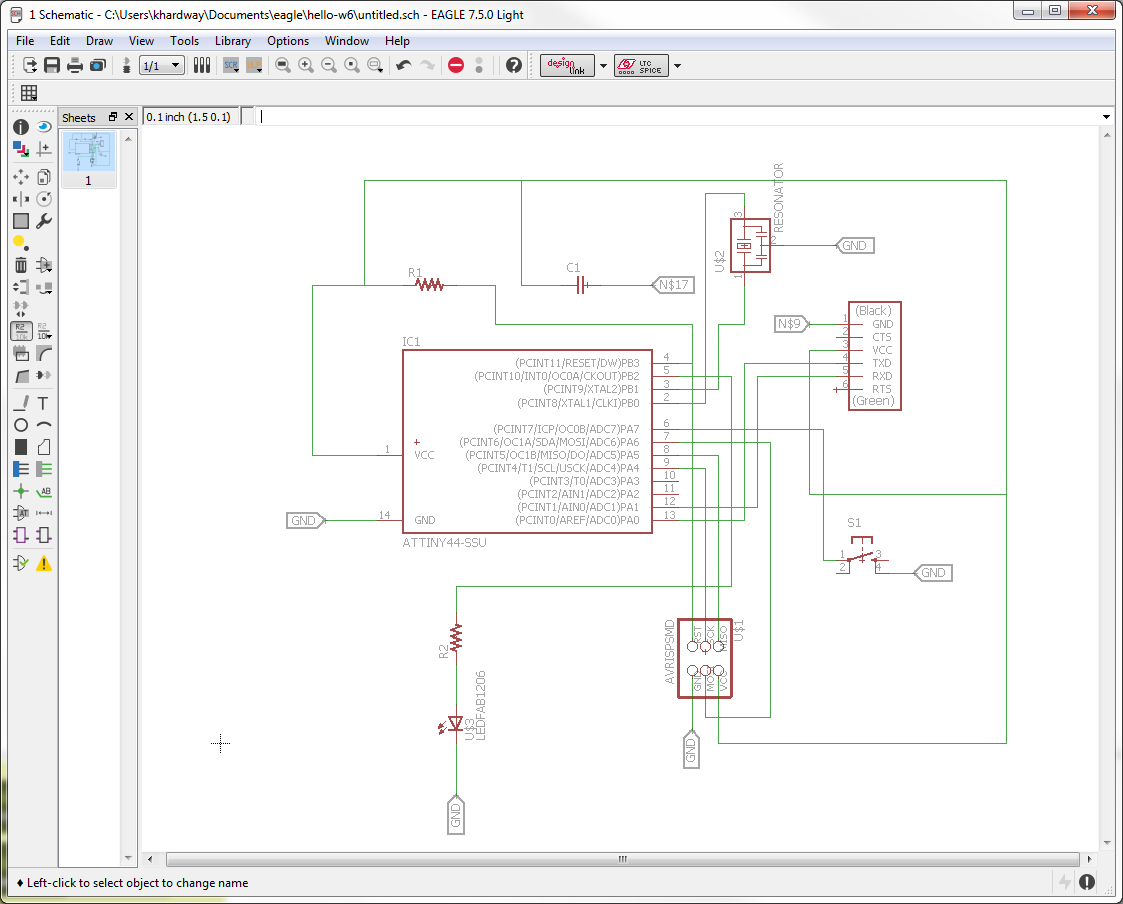
The schematic was fixed and now all ground connections are completed.
Select the File Menu and then Switch to Board command. Below are the connected components that need to be placed on the board.
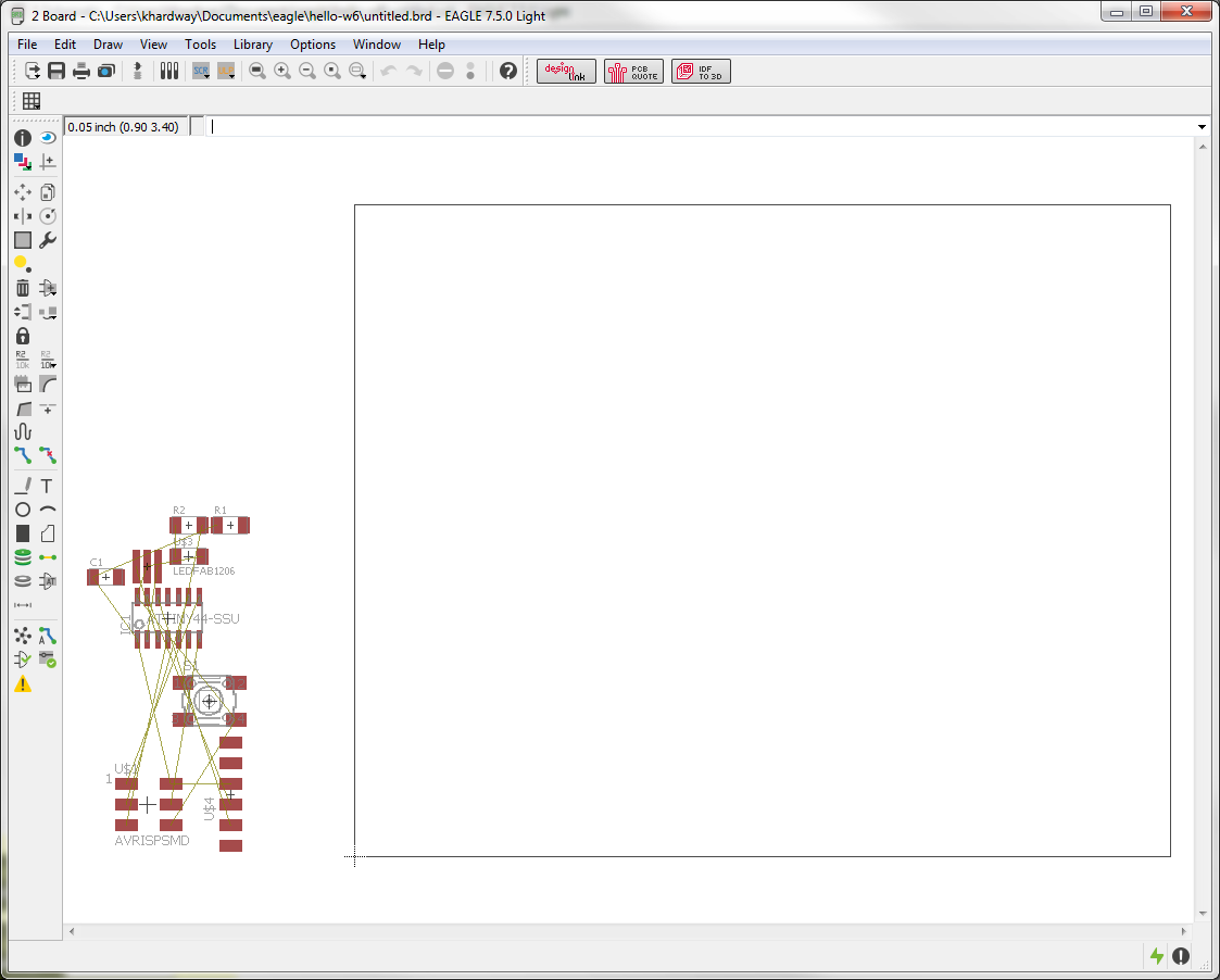
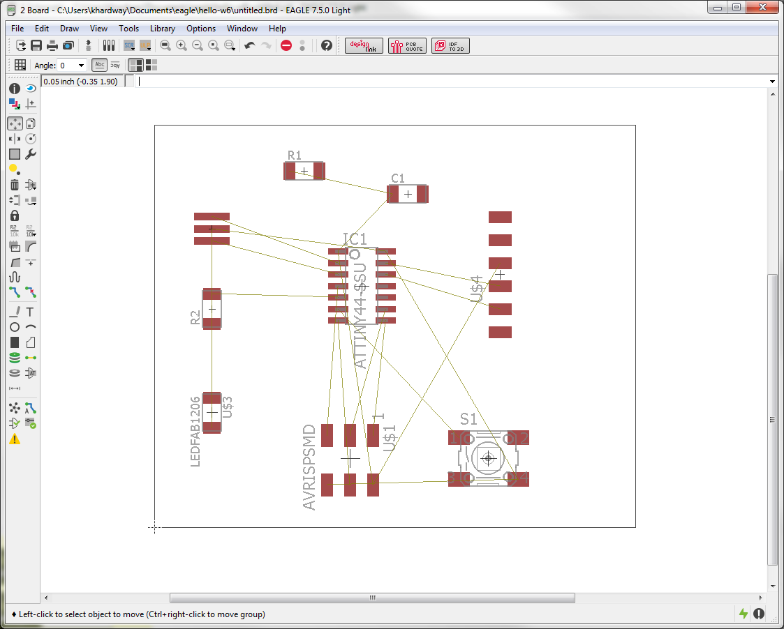
Move the components to the board area and rotate them as best as possible for the shortest distance between components and connection points.
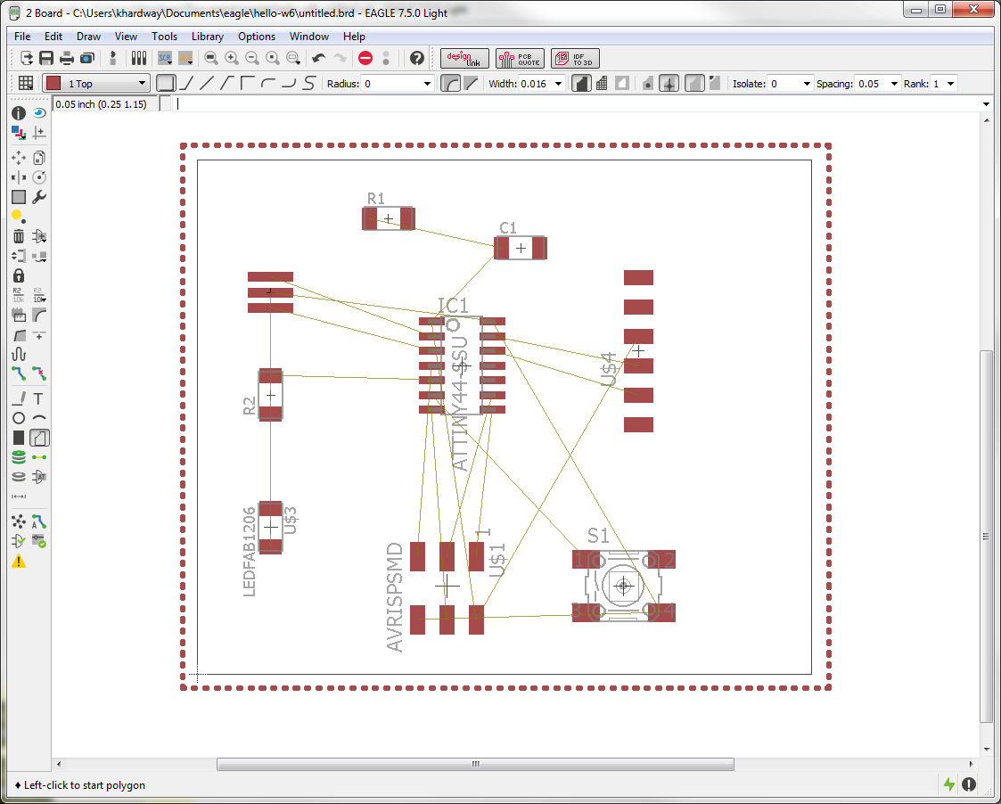
Once the comonents are moved and rotated, resize the board and draw a rectangle on the TOP layer that will represent the ground plane. Add the name "GND" to this rectangle. Notice there is no connection to ground on the capacitor and header. My board was made without two ground connections and had to be jumpered to ground, as explained above.
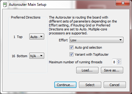
I used the autorouter in EAGLE. The tutorial I was working along with suggested "netclasses" be set before starting the autorouter. I added a couple of millimeters to the suggested settings while following along with this tutorial by Jason Blum.
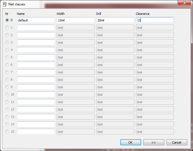
AutoRouter can be selected from the "tools" menu or selected from the left icons. The only change made here is to set the bottom layer as N/A.
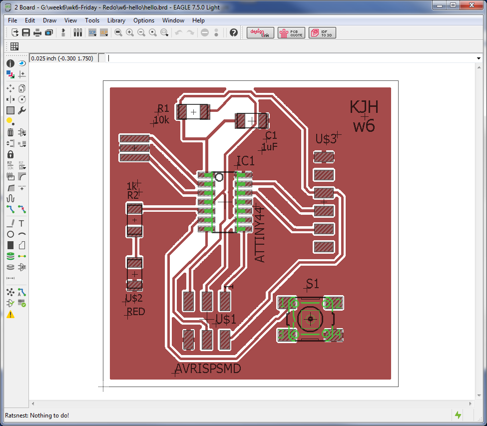
Here is the completed board. I did change a couple of layer colors for more clarity. Notice there is a connection to GND on both the capacitor and header. This is the corrected board, but not the one that was cut. Make sure the ground plane is continuous throughout the board.
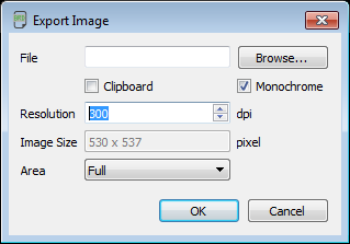
To export the traces as PNG, turn off all layers except for "Top". To export the board as PNG turn off all layers except "Dimension". Make sure the resolution is the same for both files. Mine is set to 300 dpi.
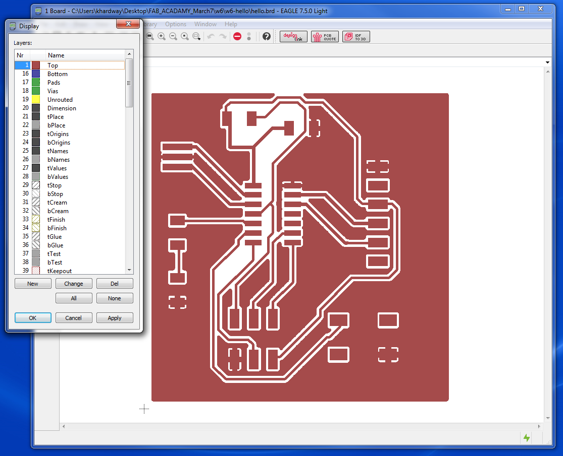
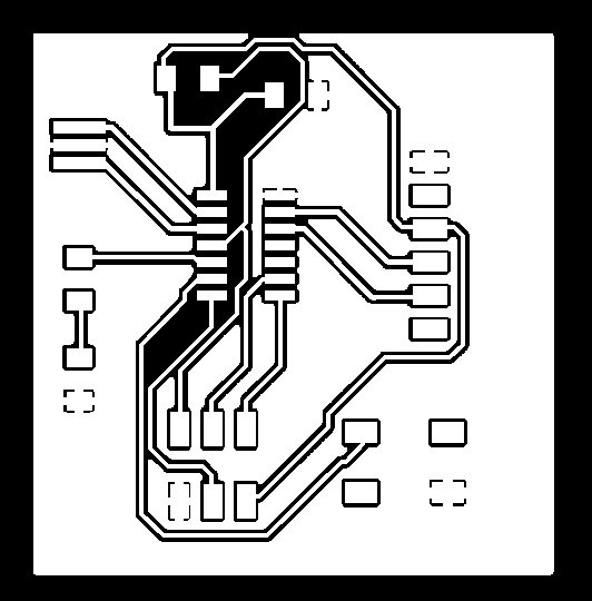
Here are the images for the traces and the board outline. The board outline needs to be filled in order to be cut.

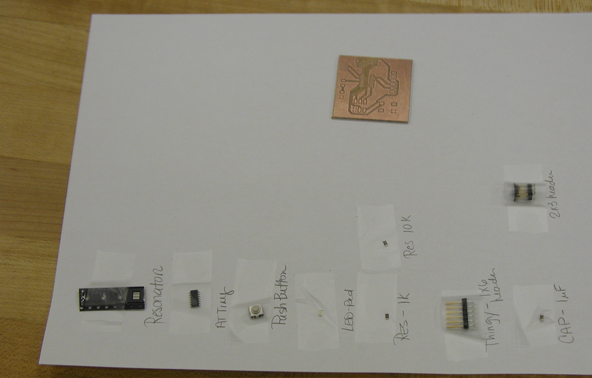
Below is the board and components required to solder. all components were taped to a piece of paper for organization.
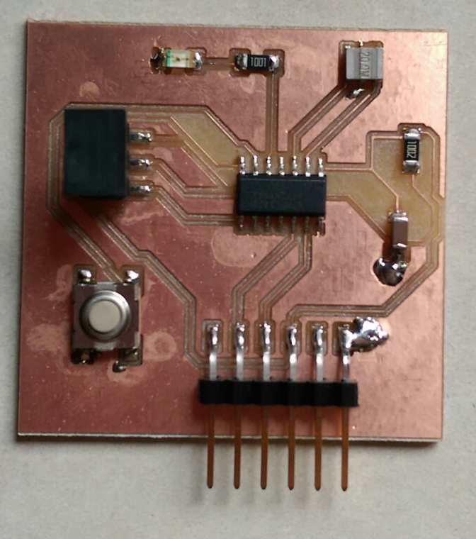
Here is the completed board with the two large blobs of solder on the capacitor and header in order to bridge to the ground plane. I still have the protector over the AVRISPSMD.
