This week we were given the group assignment to test the limits of our 3D printer and to print something that could not be made subtractively. I printed out a door hinge, intact; the pin can't be removed from the two hinge sections.
We were also given the task of scanning an object and optionally printing that object. I chose to scan a model of a toy horse.
Hardware and Software Used:
MakerGear: link
Dimensions SST 122es: link
Models Used:
In the model below, the middle cylinder revolves around a shaft. the clearance was originally set at 0.02 inches. This was successful on the Dimensions printer, but not on the MakerGear. The support material could not be broken away from the internal mates. I also tested this on the Maker with a 0.05 gap between parts ...... the part failed to successfully print the middle cylinder and the print had to be stopped.

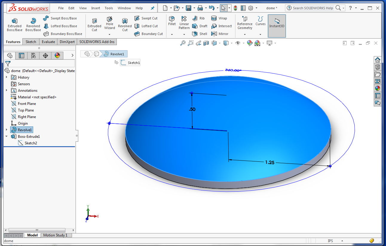
A dome feature was created and 3D printed. On both printers is was better to print this model vertically because of the "steps" on the surface on the orientation below.
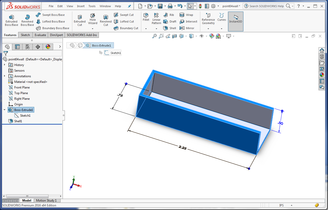
A box (2.75 x .75 x .5) was created and 3D printed. The wall thickness was created at 0.050 inches. On both printers there was no substantial shrinkage of the external size of the box. However on the wall thickness the Dimensions measured just over 0.050 inches and the Maker measured just under 0.050 inches.
I created a hinge in solidworks with 3 separate parts; the left side of the hinge, the right side of the hinge, and a pin. All three pieces were assembled and output as an STL file as a single assembly. This hinge can't be taken apart. The clearance between the mating parts has to be 0.02 inches (or one half millimeter), which is the limitation or the Dimensions printer (anything less than this measurement will cause the assembly parts to be melted together). This hinge could not be printed on the MakerGear printer because of the type of support material and where the material has to be placed within the assembly. It is impossible to "break away" the support material from the interior of the hinge and pin.
The image below shows the three hinge pieces and the assembly that were created with SolidWorks.

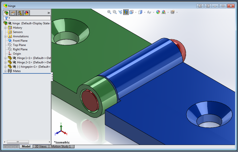
The image image below is a cross section showing the clearance in the assembly. The clearance, in order to have a successful print, is to assemble mating parts with 0.02 inches in clearance or one-half millimeter. If this value is less, the assembled pieces will be fused together.
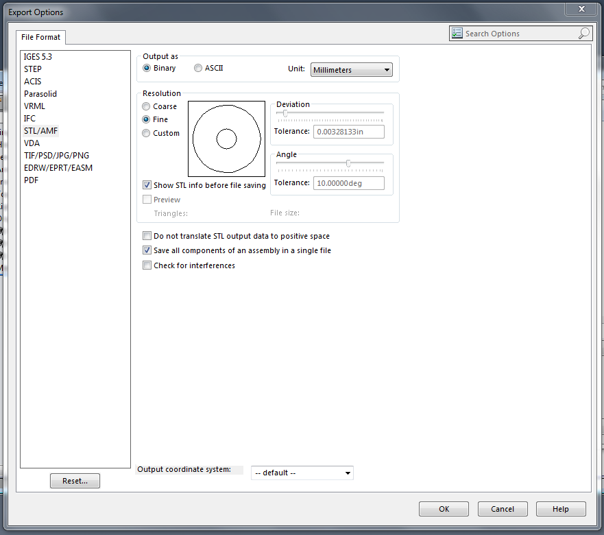
SaveAs STL and options button. Set output as Binary and the units as created. In thic case, the hinge was built using millimeters. Make sure all components are saved as a single file. This way they will be printed as a complete assembly instead of individual parts This hinge, if printed as individual parts will never be able to be assembled.
Preview the STL file. there are 4588 triangles. Solidworks (FYI) has a limitation of 20,000 triangles.

Open the STL file in CatalystEX. This is not the optimum orientation for this hinge to be printed.

The important part of this hinge is the hinge pin and the mating cylinders on each hinge section. The best resolution for cylindrical features is to be printed vertically instead of horizontally. Printing cylinders horizontally results in steps on the surface. The best rotation for hinge to be printed is shown in the image below:
STL being processed. The dissolvable support material (gray) is added where necessary. The individual layers can be viewed by selecting the "Layer View" buttons on the right side of the Orientation tab.

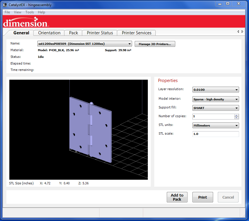
The hinge is then added to the pack to be printed. The pack details are on the right. The pack can contain anything that fits in a 10 inch by 10 inch square surface. The height limitation is 12 inches.

Units of the pack changed to inches for my understanding. This model took almost seven cubic inches of model and support material combined. It is much cheaper to purchase brass hinges than to 3D print them. If I would have scaled this model down, the spacing between the mating parts would also decrease and the assembly would fail to move. Everything would be fused together.

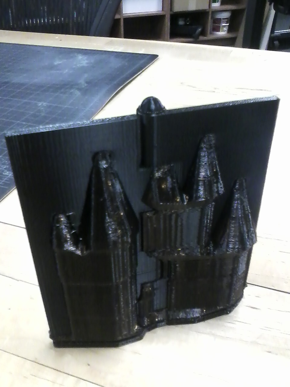
Took over 12 hours for the print to be complete. The hinge is standing vertically on a table. The support material is not yet dissolved.
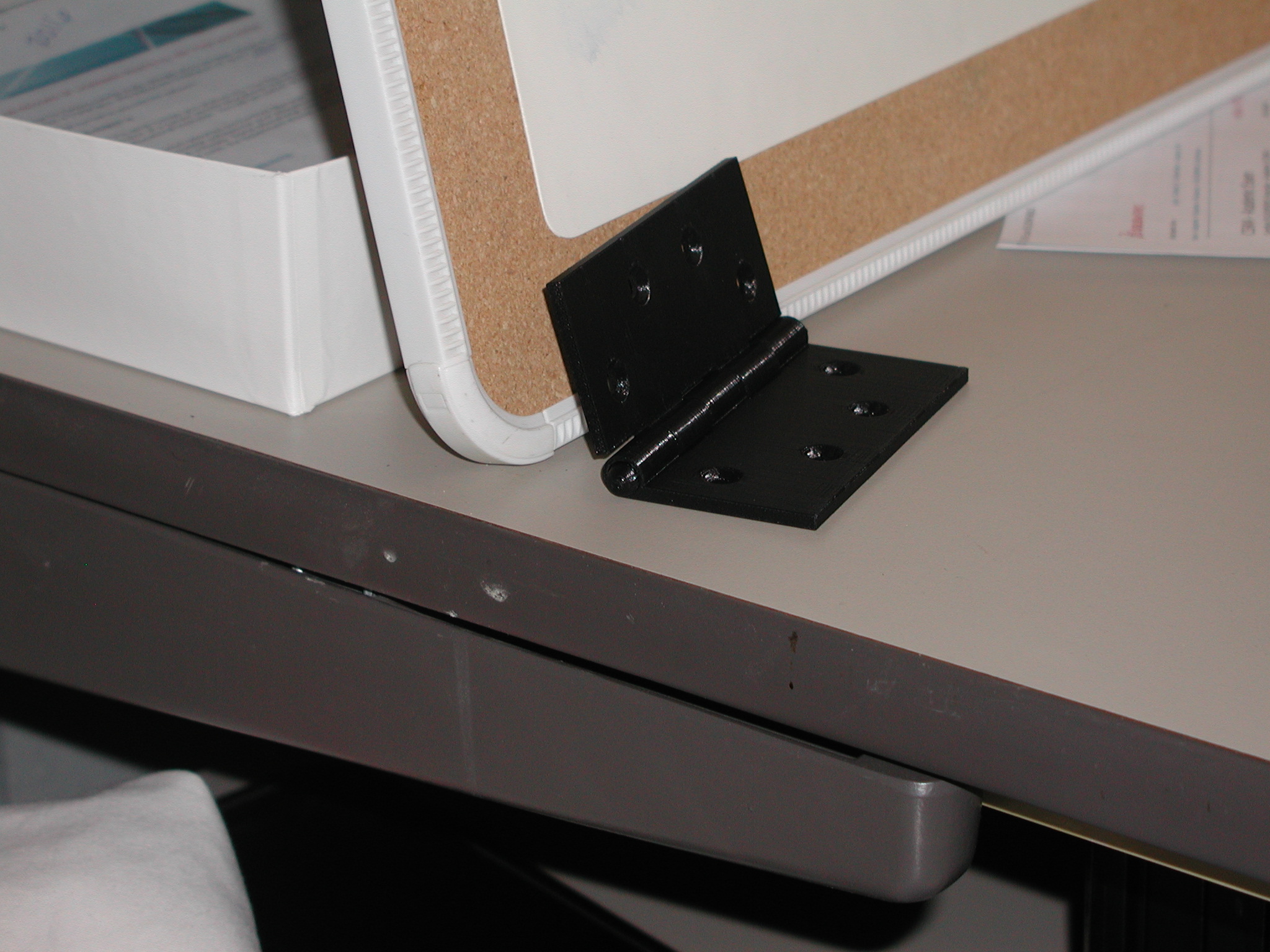
Support material dissolved and hinge complete.
The first step to a successful 3D scan is to properly prepare the model. Shiny surfaces need to be dulled, clear and black surfaces need to be painted with a dull paint or powder. I have found that powder does not work very well, but in some cases you have no choice because the model is too valuable to completely paint. The best way to prepare a model is to spray paint with primer. I used a gray priner on this horse. Black and clear objects do not scan.
Another good practice for a good scan is to put the model on a piece of black plexiglass over a turntable. The plexiglass will not be picked up in the scan. If possible, use the reflective, randomly-placed dots. This particular scanner needs to be able to see four dots at a time for optimum scanning. You can scan without the reflective dots, but you always have a point of reference when they are used. The model can be moved, laid down, or turned in any direction and still achieve a successful scan.
The image below shown the properly prepared model and the scanner. The tail and mane will not scan and must be moved out of the way as the horse turns around on the table.
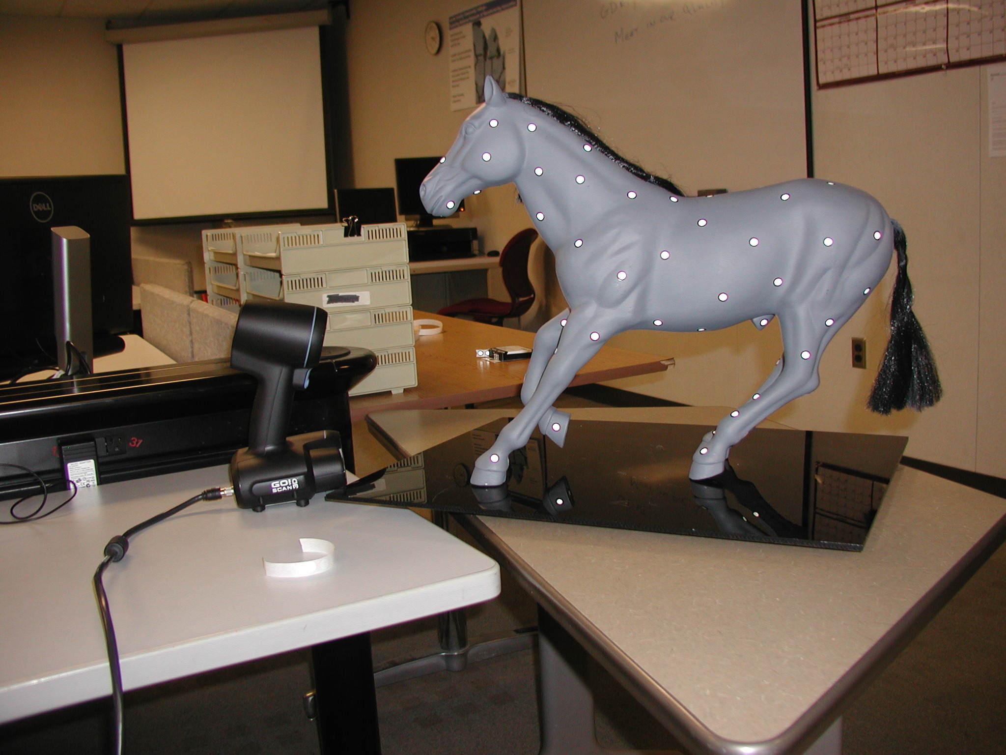
This particular scanner has to be held at a 15-inch sphere from the model and can't scan small items. the recommended size of the model is to be "bigger than your head". Notice the horse appears to be standing on nothing. The scanned did pick up some of the table top under the plexiglass, but that is easily removed.

The scan is complete and a mesh is created. Over 181 thousand triangles are created and yes, there are some holes that need to be patched.The top of the neck leaves quite a large hole where the mane was attached. If the model is properly prepared there are only a few holes, no spikes, and no reverse normals, in the mesh.
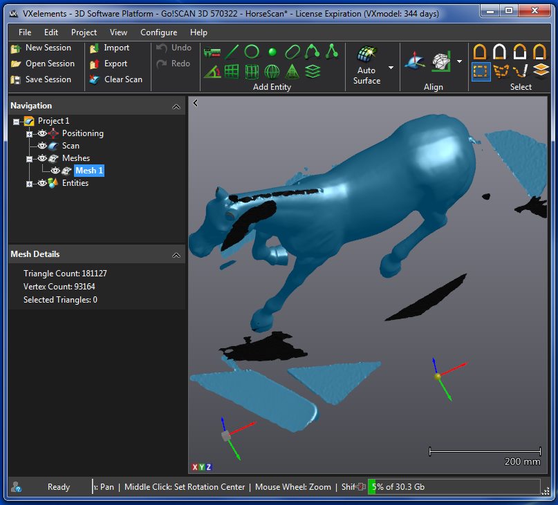
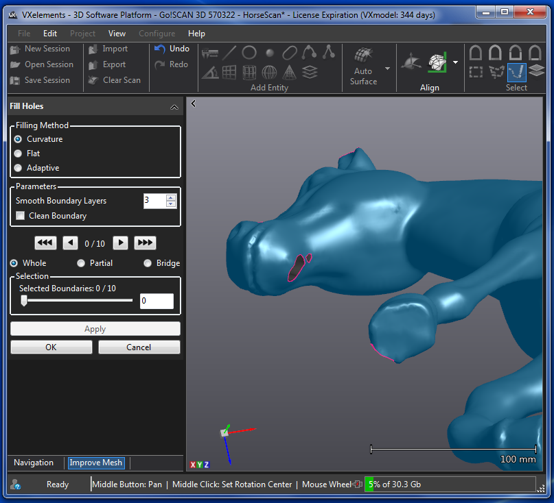
The mesh that is not attached to the horse can be deleted and the holes can be patched. You can see three holes below. This software can estimate the curvature of the area and does quite a good job at filling holes. Sometimes bridges need to be built with splines so surfaces can be built up. This was not the case with this model.
Here is a close up of the 2mm triangles that make up this horse.
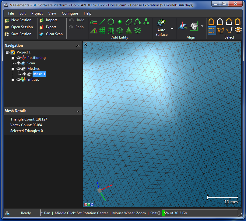
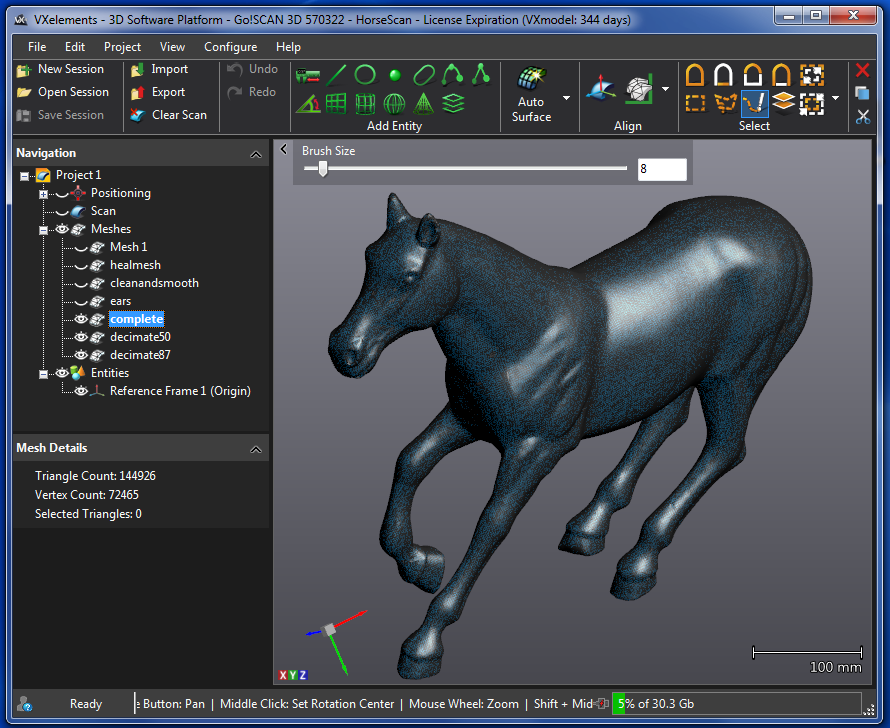
The completed horse shown as a surface and mesh. There is no reduction in this mesh of over 181,000, 2mm. triangles. The STL file created with this mesh is just over 7MB.
The image below shows the mesh at an 87 precent decimation. Larger triangles are created on the body and the smaller triangles are reserved for the details. This file is 3.5MB in size and over 72,000 triangles.
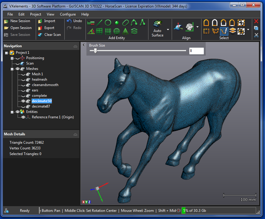
The image below shows the mesh at a 50 precent decimation. Even larger triangles are created on the body and the smaller triangles are reserved for the details. This file is under a MB in size and just under 19,000 triangles. This is the STL file to be printed.

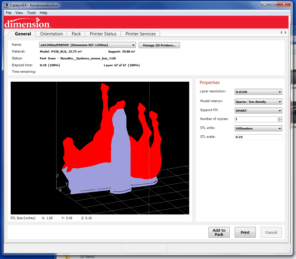
Here is the horse in the CatalystEX printer software. I wanted his legs as vertical as possible to print with the best resolution and show no steps in the surface of the legs. This model is printed at quarter scale.
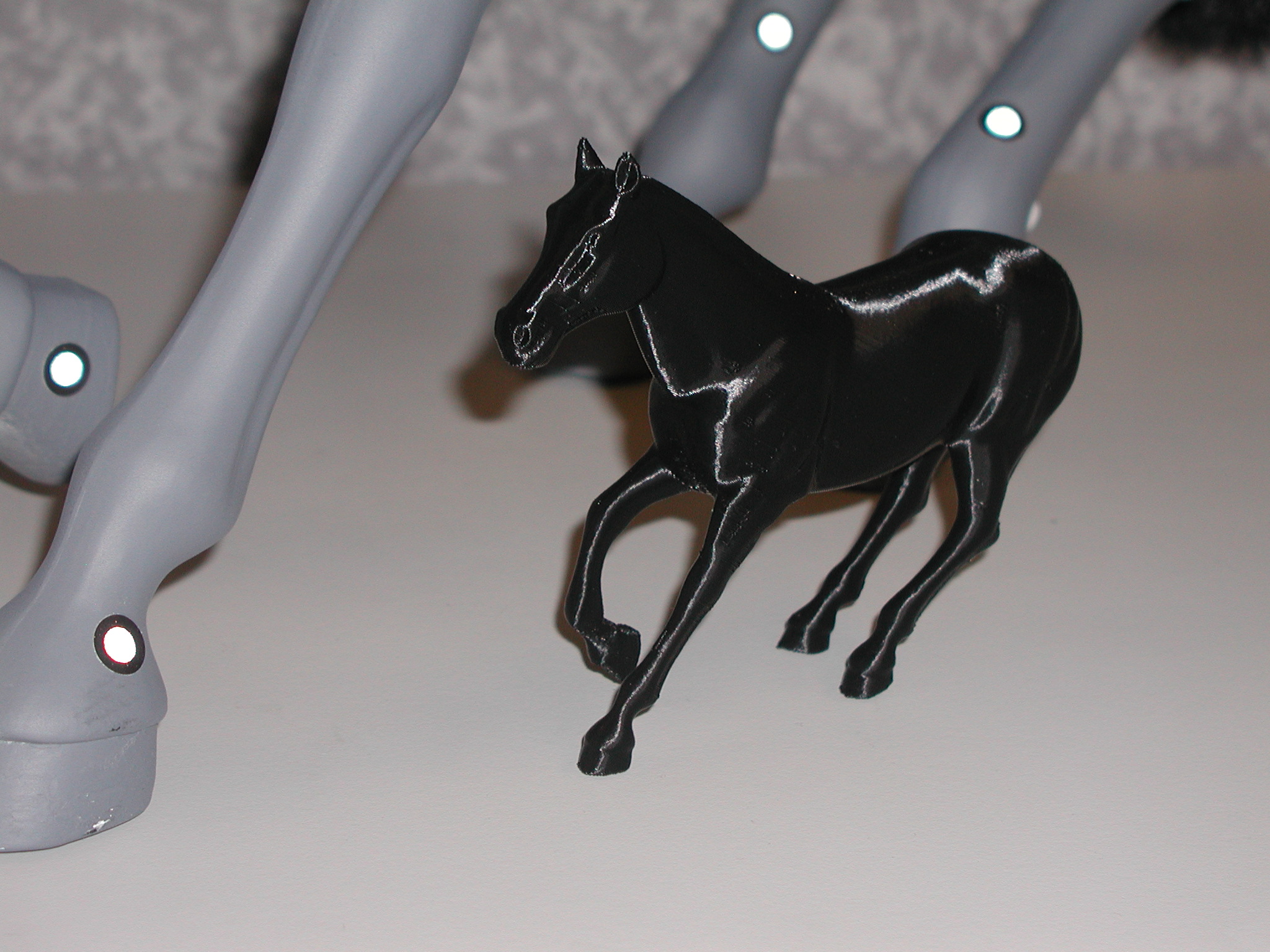
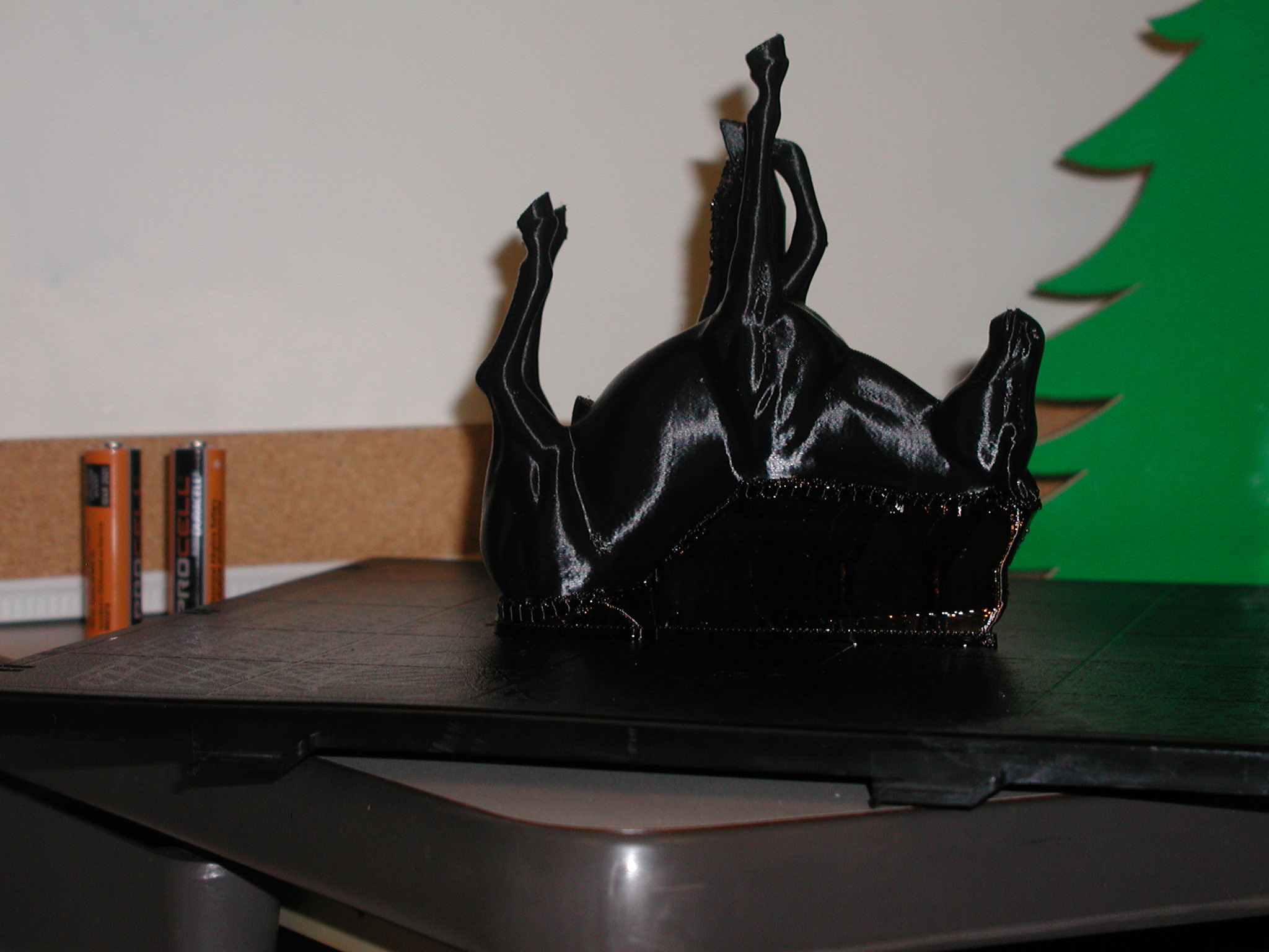
This is the model just as it came from the printer.
Standing next to the original.

Close up.