
This week we were given the assignment to make an In-Circuit Programmer.
My first attempt at this assignment was unsuccessful and had to be redone. The starting-over steps for this weekly assignment is on the bottom of this page, along with the image of the second, and successful, ISP.
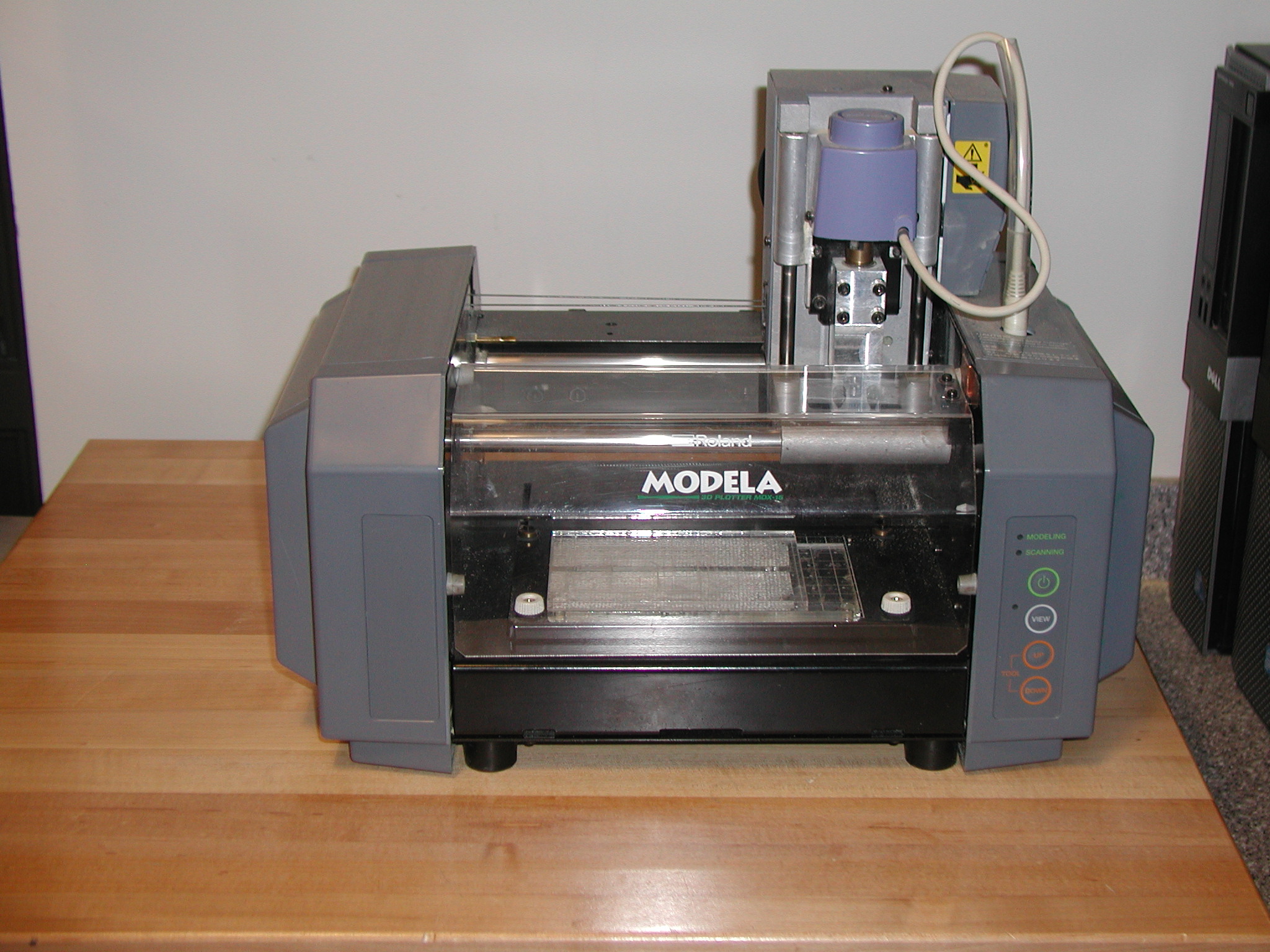
The following link was followed to mill the board on the Modella. It is importnt to read the entire document before proceeding. Make sure special attention is paid to the workaround. When using the 1/32 inch bits, be very careful not to crash the tips into the top of the board. This is a fragile bit and breaks easily.
Other important links for downloading files and running the Modella :
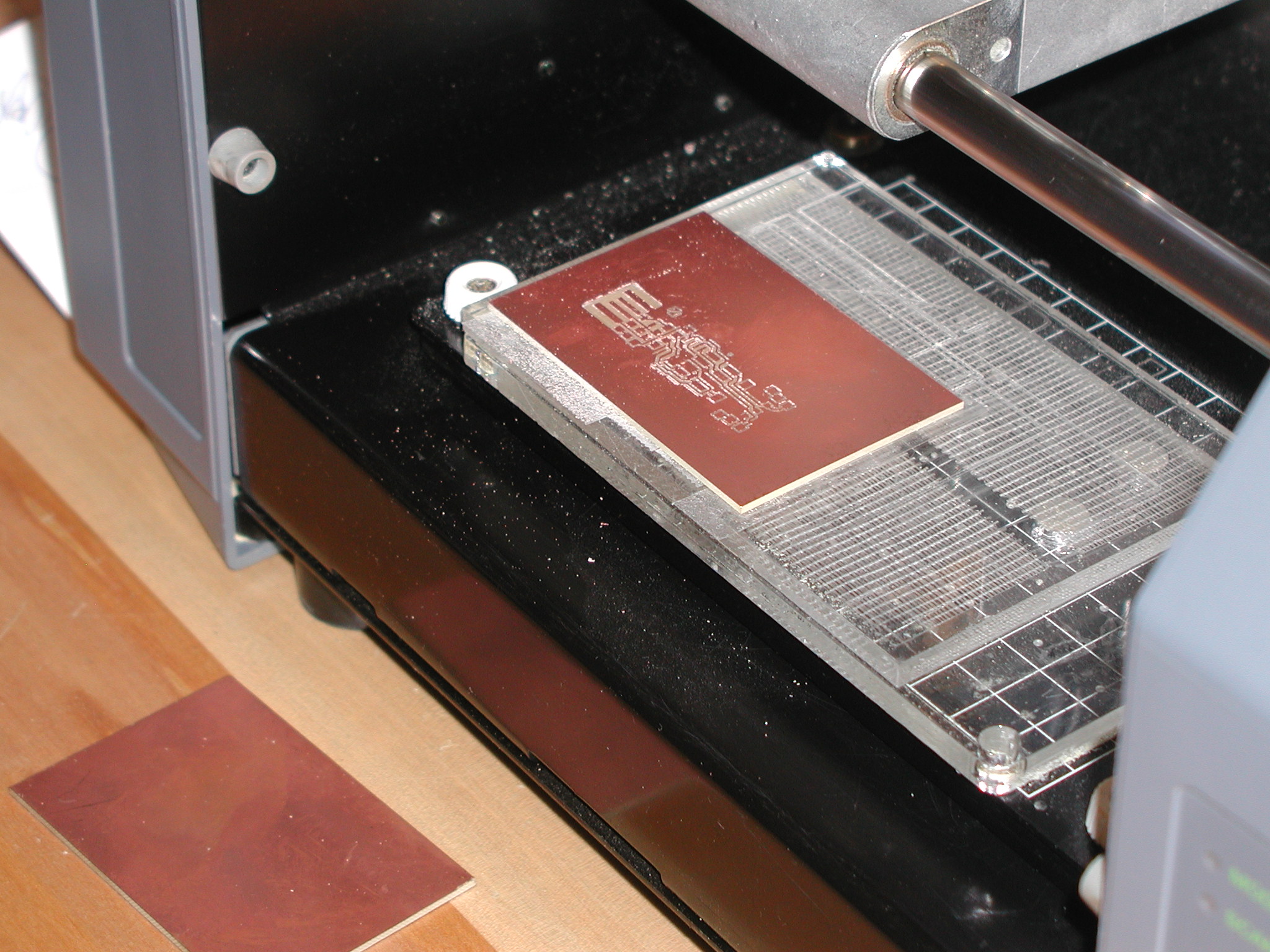
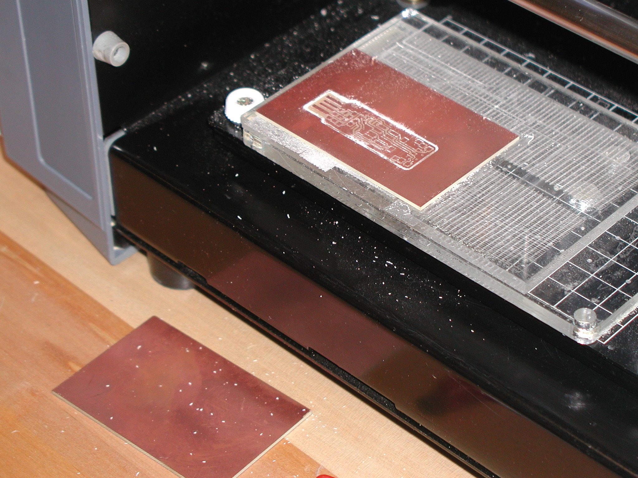
The following images show the process of the board cutting. The detailed explaination is on the page "Milling the Board" on the above link "FabTiny*ISP". The board is secured to the Modella with double-sided taped to the sacrificial layer with special care not to crease or double up the layers of the tape. The board needs to be as level as possible in the Modella.
Securing the material in the Modella with tape.

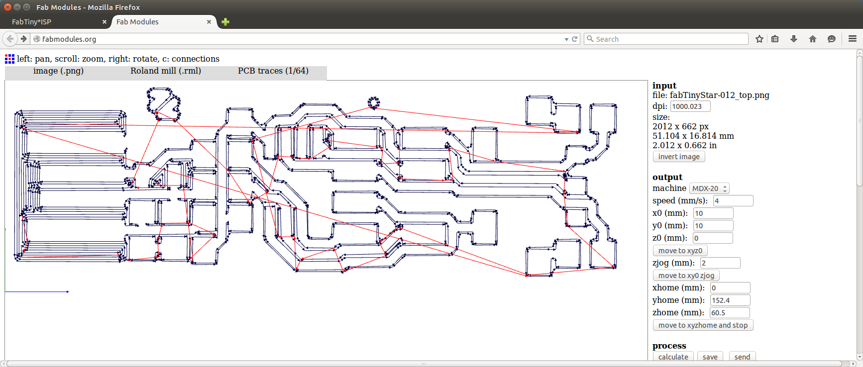
The fillowing image shows the movement of the bit with the 1/64 inch end mill. Note that the settings here are the same settings as shown on the "workaround" on the web page. There is an issue with cutting angled traces unless the diameter of the end mill is changed. The black lines are cutting and the red lines are movement of the tool above the board and not cutting.
After the traces are completed do not remove the board; set up the Modella to cut through the material with the 1/32 inch end mill.
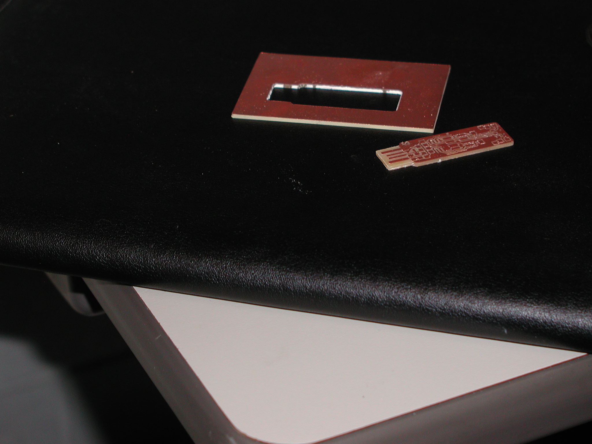
Completed cuts. Board is ready to de-burr by washing with soap and water.
Ready to solder the components
The following link was referenced in order to populate (stuff) the board with the components.
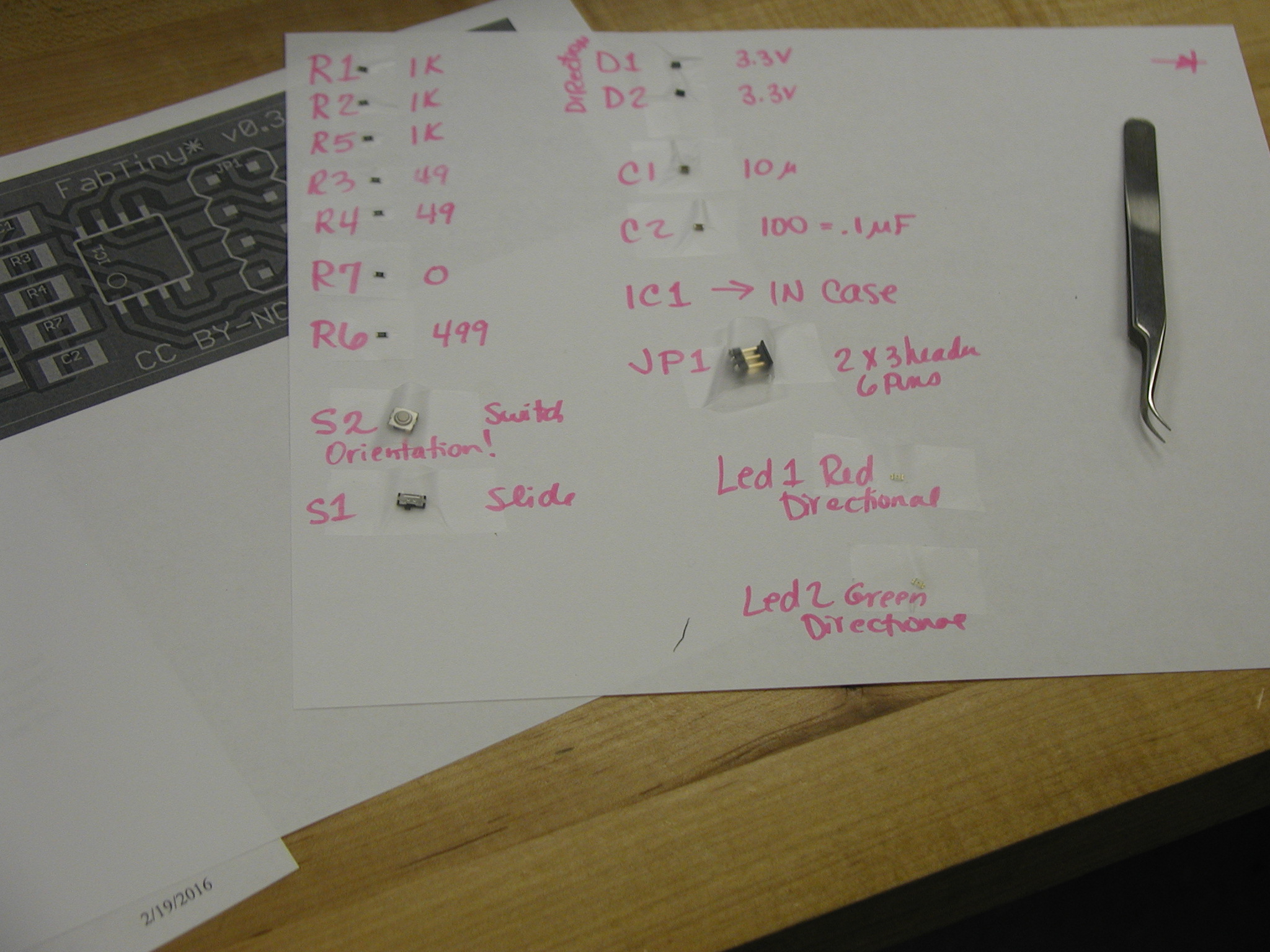
The list of componets are on the link "Stuffing the Board" above. It was decided to tape every component to a piece of paper to keep things organized.
Everyone hard at work
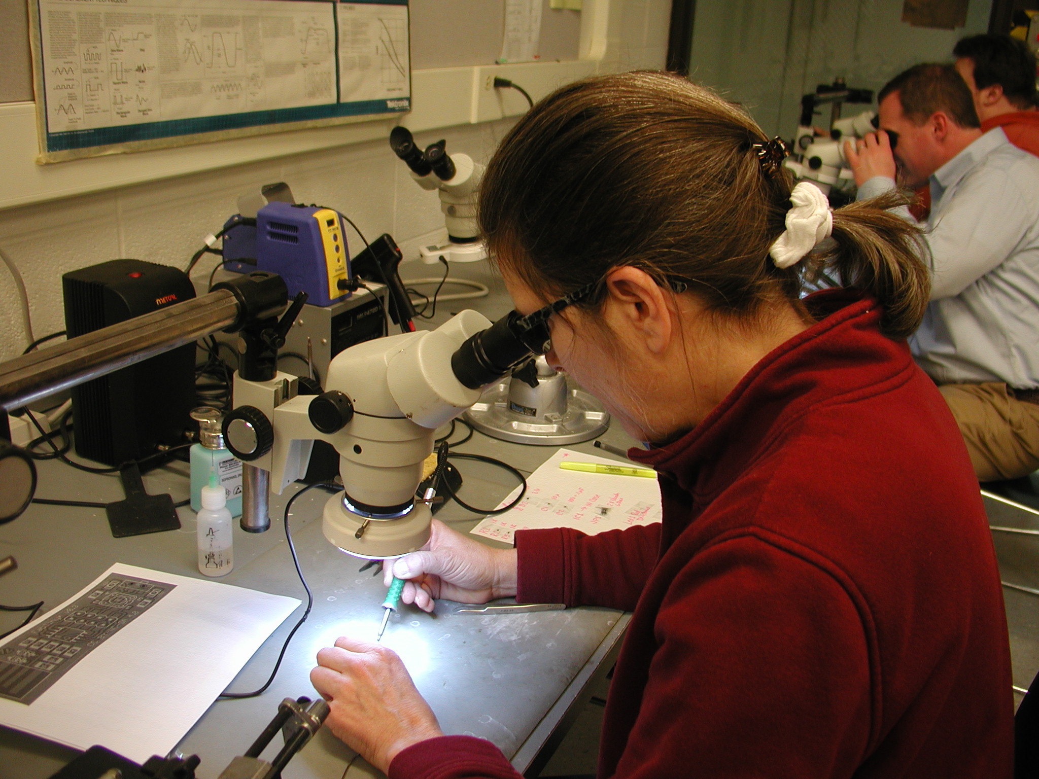
Got a couple of components soldered.
A couple hours later .... a completed board ..... now on to programming!
The following link was referenced in order to program the board. Steps were followed on the link below. This section on programming was not successful.
This is the point where things stopped working. The firmware would not flash. It was determined that I had unsuccessfully soldered a component or fried a component. I am not sure what happened. Anyway, I tried to remove the processor chip using a copper braid to absorb the solder. The trace came apart from the board. Total frustration today, but I did learn a bit about soldering and how much time it takes. Hopefully I will get better on the next board!
I will have to start over and cut a new board.
Stay tuned for updates.
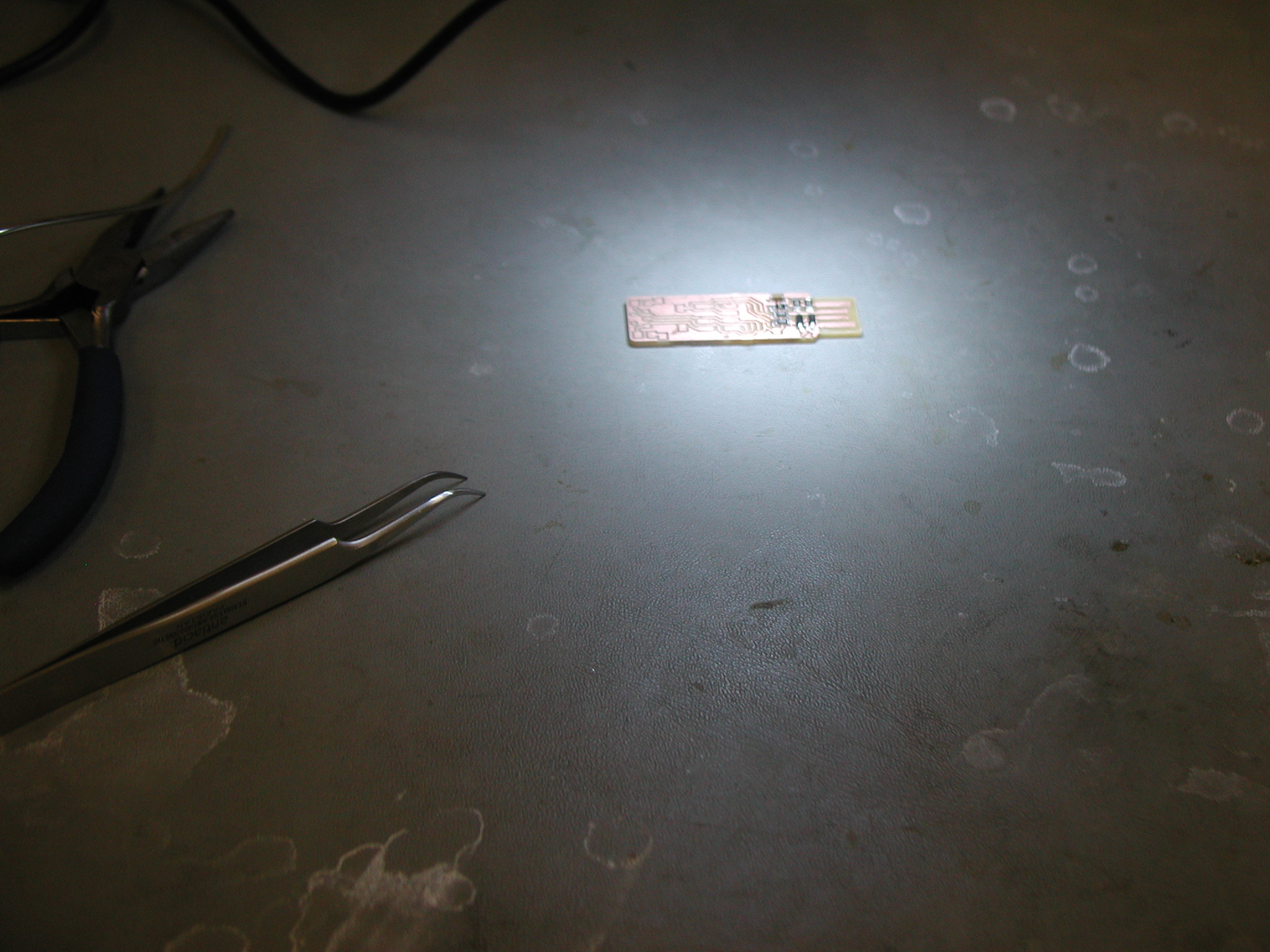
The above steps were completed for the second time. The board was re-cut on the Modella Mill and components were soldered to the board. This board now needs to be programmed.
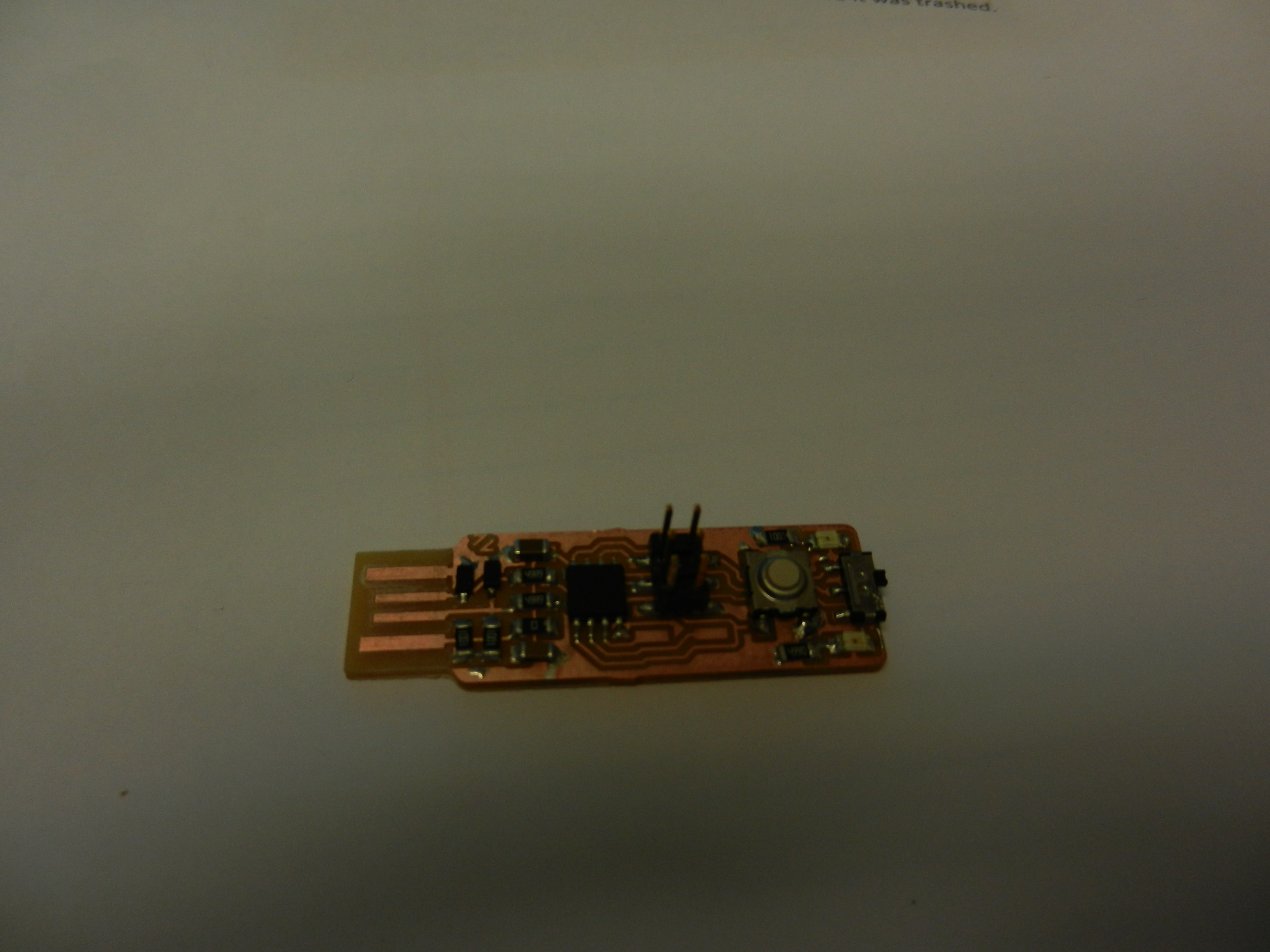
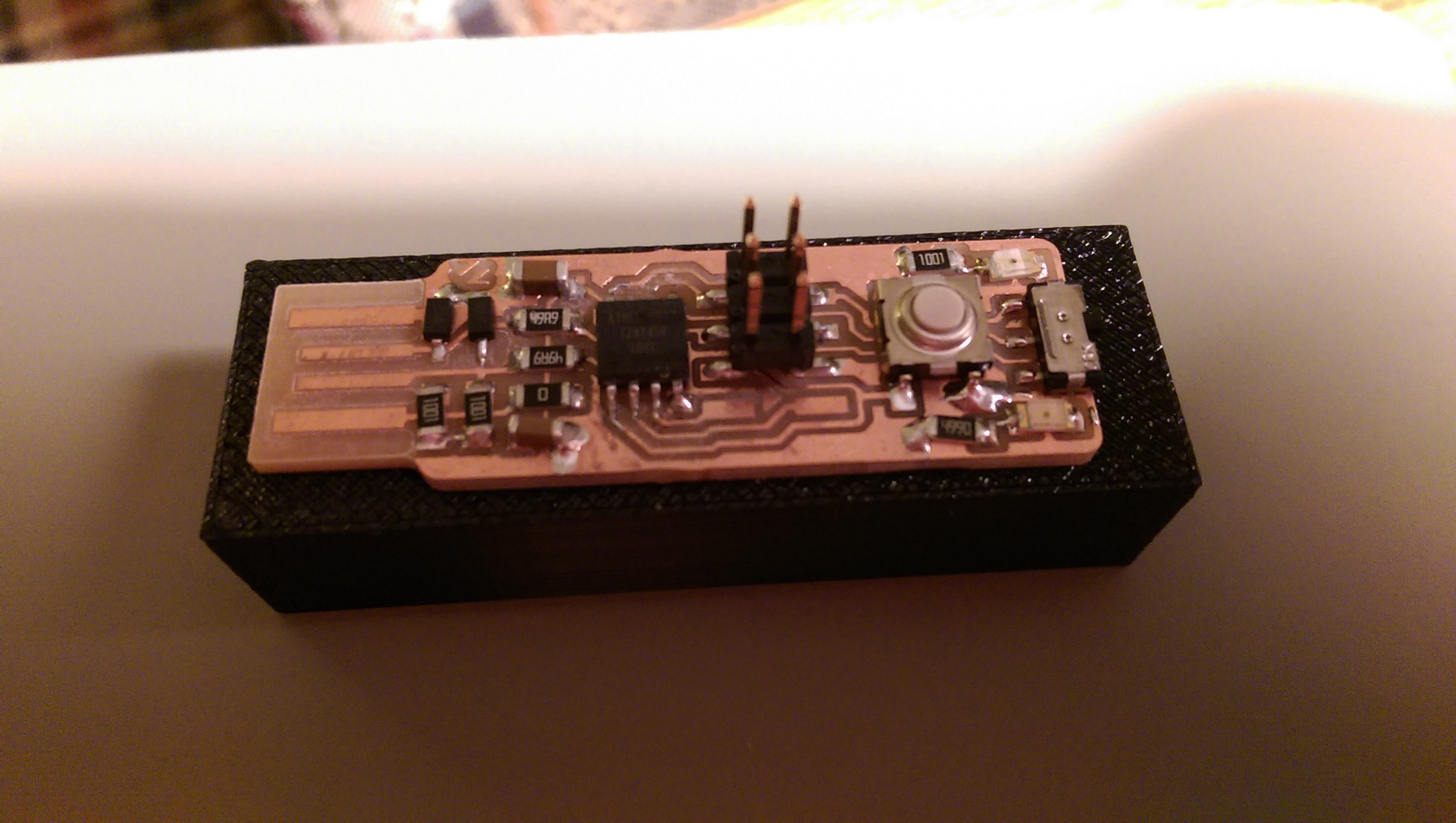
Below is an image of the second board.
The following link was referenced in order to program the board. Steps were followed on the link below.
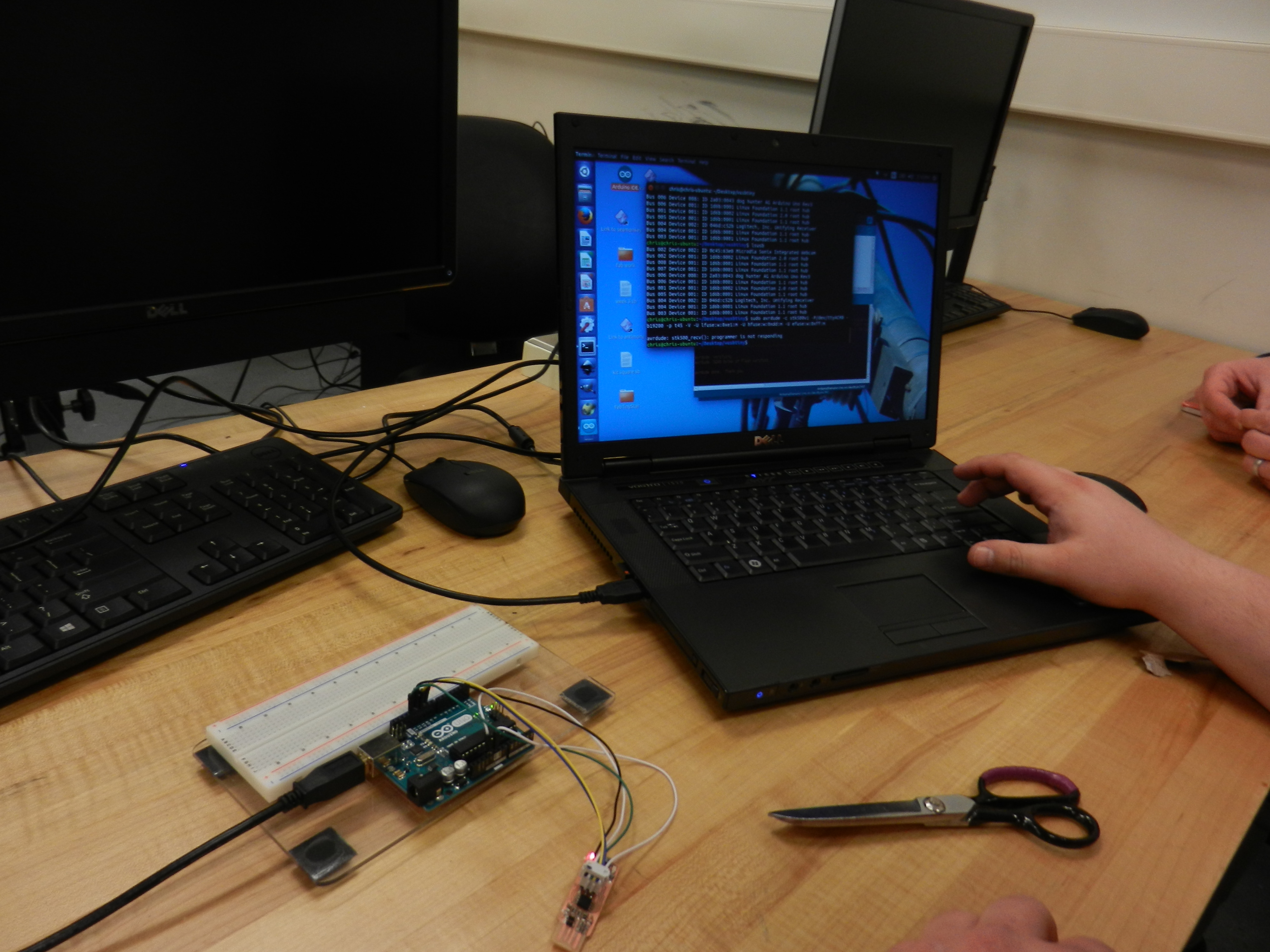
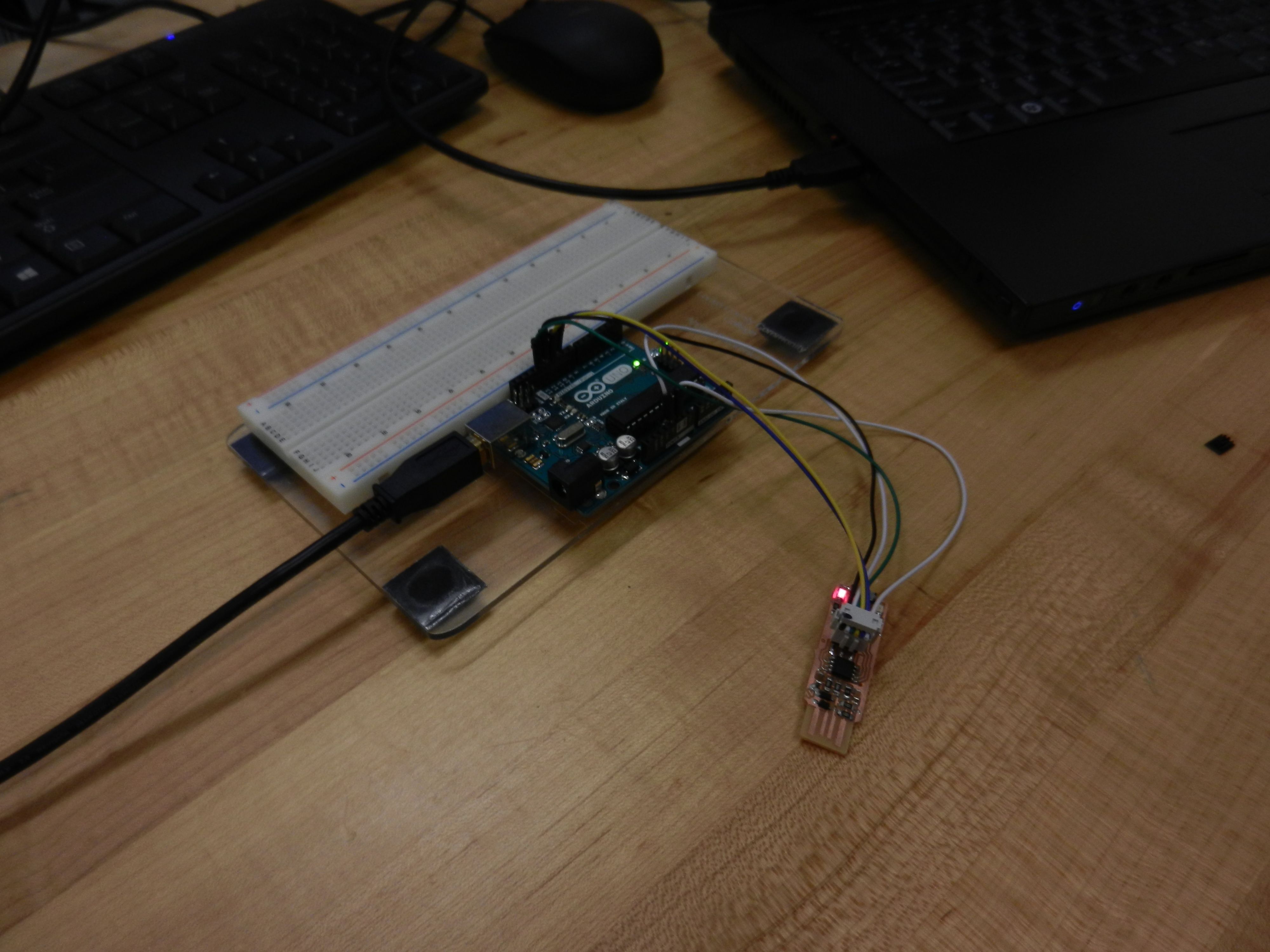
The Arduino was connected as described in the instructions and the following command was executed.
avrdude -c stk500v1 -P/dev/ttyACM0 -b19200 -p t45 -V -U lfuse:w:0xe1:m -U hfuse:w:0xdd:m -U efuse:w:0xff:m