
This week we were given the task to review and use as many computer aided design packages as possible. I thought I would begin by trying out one from each category. The final outcome is to create drawings of the final project design.
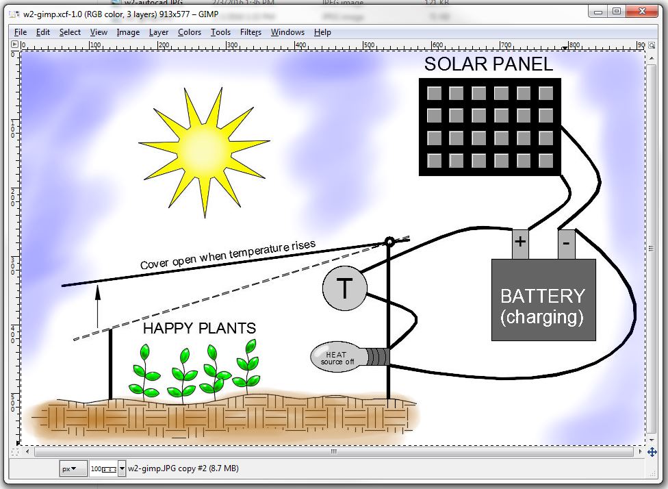
After many unsuccessful attempts to draw a straight line with a mouse as the input device, I decided to use the image of my original design that was created in DraftSight. I modified the file from night to day using AutoCAD (images are both shown below). The image was then captured and painted using GIMP. Using GIMP as a paint package is the only use I have for my design.
This is the result using GIMP:
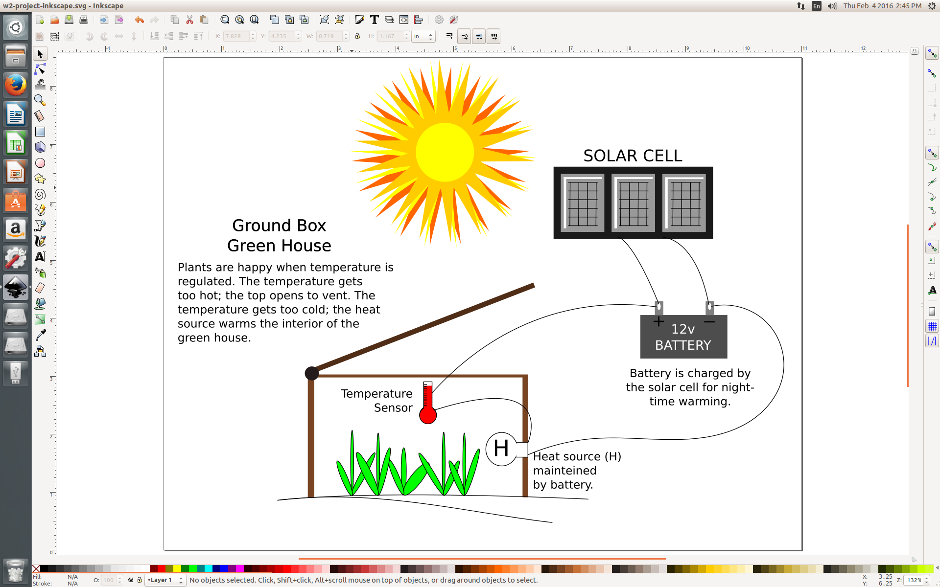
Using Inkscape, I was able to completely recreate the design drawing of my project. Drawing straight lines, circles, rectangles, text, and splines was much easier than in my previous attempt with GIMP. The objects can then be grouped together and moved as a single unit to place them around the drawing. For example, the sun shown below was created using three 18-point stars and an ellipse (with equal X and Y values) that were grouped together. The solar cell was created using only rectangles that were grouped together. When text is entered using Inkscape it acts as a single paragraph that can be copied and edited.
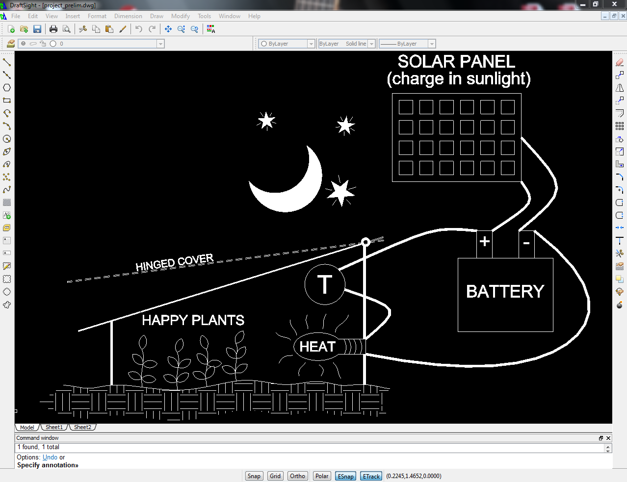
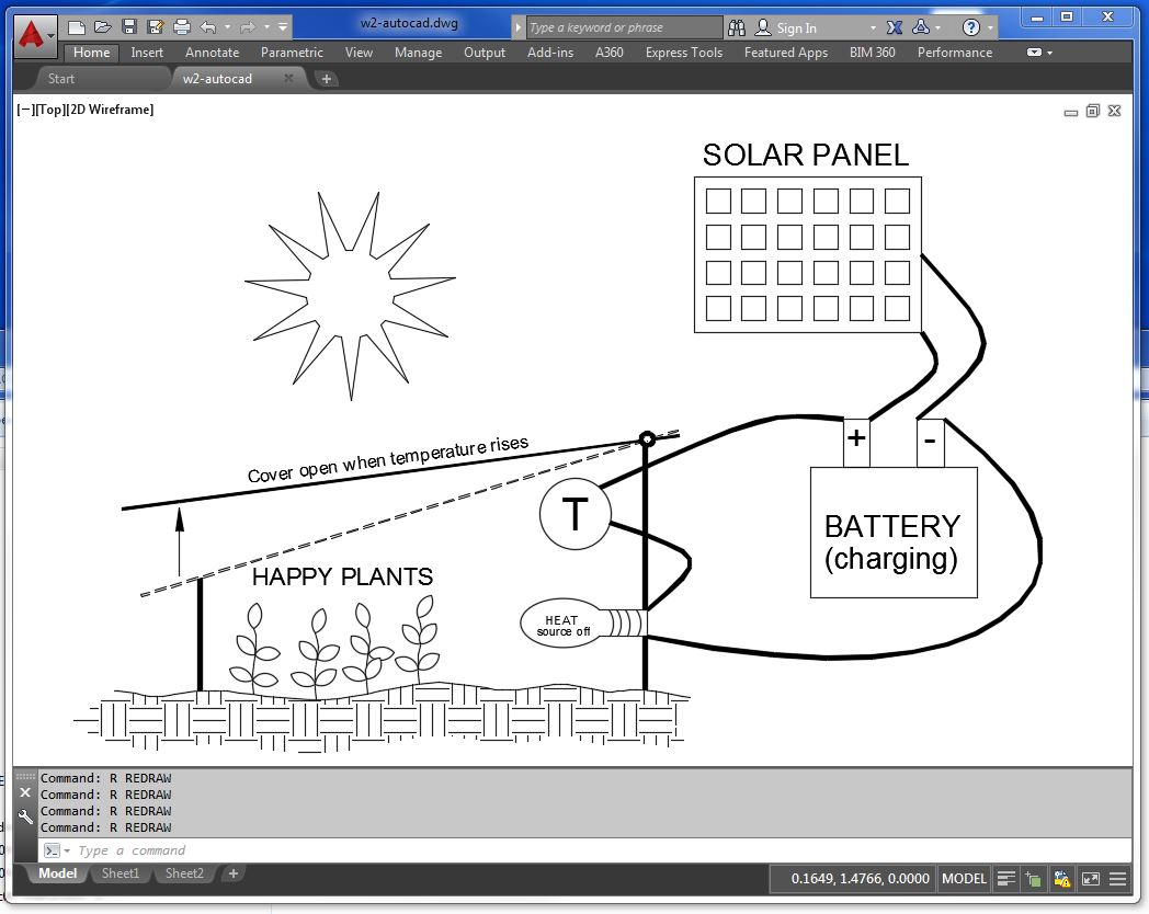
I am including drawings with Draftsight and AutoCAD in this section because they are also being used for 2D vector software for drawings. The objects (lines, circles, and text) in AutoCAD and Drastsight have starting points, ending points, center points, insertion points. Similar objects in Inkscape have bounding boxes and are much harder to determine actual sizes. For example: drawing a rectangle in AutoCAD requires the user to input two coordinates. These coordinates can be 2,2 and @4,1. This would result in a rectangle that is 4 units long and one unit high, with the lower left corner of the rectangle at the coordinate (2,2). The same rectangle drawn using Inkscape would be described at a location of x: 2, y: 2, width: 4, height: 1. Circles in Autocad require an input for the center coordinate and the size of the radius. Circles in Inkscape require the lower left corner of the bounding box to be identified and then the size of the circle.
This is the result with InkScape:
This is the result with DraftSight:
This is the result with AutoCAD (The drawing background is changed using the "options" command.):
I have modeled only the greehnouse. I am beginning to think about how things are going to be constructed.
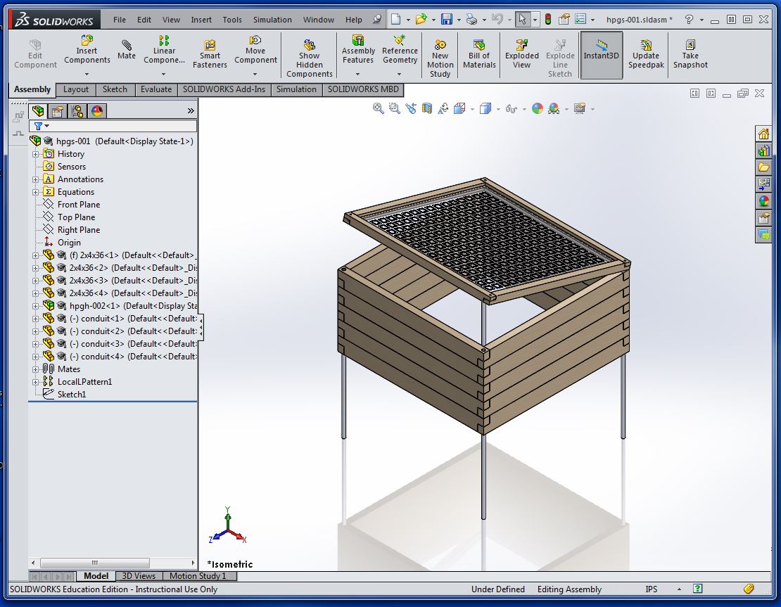
This is the assembly in Solidworks. The images below the assembly are the part models that were required in this assembly. I wanted to model this green house so that it can be disassembled quickly when the plants have reached maturity and are ready to be permanently placed in the garden. The 2x4's have holes drilled at the ends to take a piece of half-inch conduit that is secured deep enough in the garden to hold the green house in place. The cover plexiglass will have cuts in the acrylic to as to diffuse the sunlight. Each part has to be modeled separately (see the three images below the assembly) and then put together using assembly mates (coincident, parallel, distance) to create the green house.
Green House Assembly (conduit secured deep in garden soil) ..................
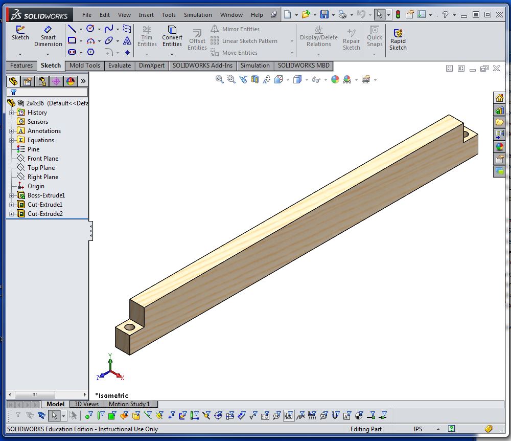
2x4x36 board required to construct the box...........
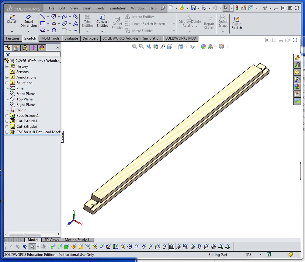
2x2x36 framing board for top ..........
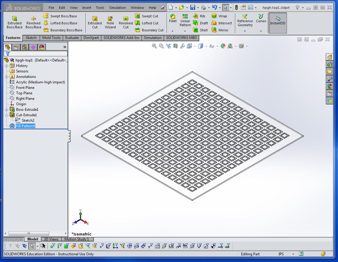
Plexiglass with cut pattern to diffuse sun .............
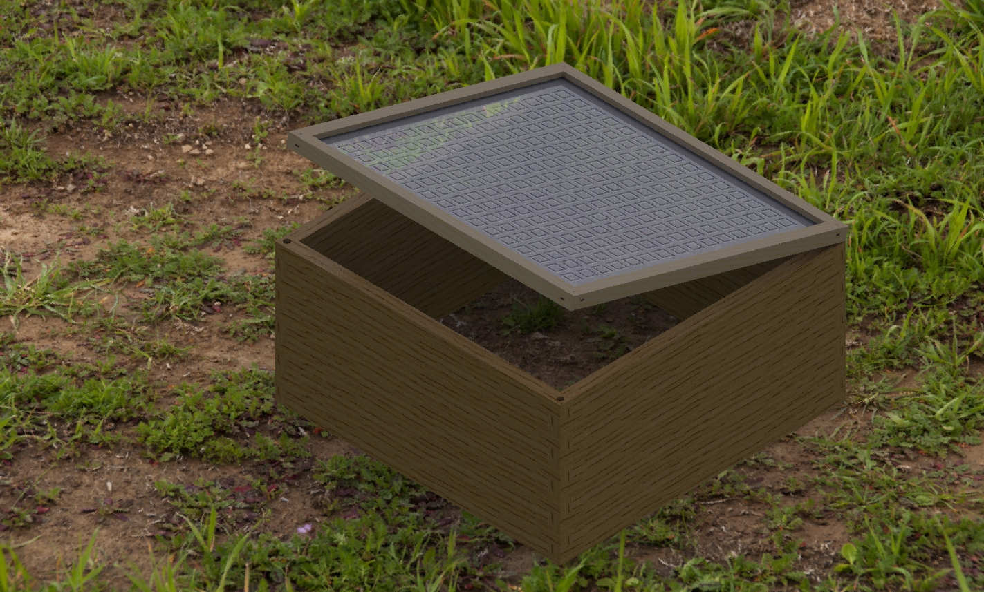
The following image is the rendered model of the green house. There is an add-on package for rendering with solidworks called PhotoView 360. Once the add-on is activated (Tools menu ..... Add-on ..... Photoview 360) I added a scene in PhotoView 360 called "Landscape 1" It looks quite like my garden in the early spring with all the weeds. The material for the box is pine and the top is acrylic. Once the material is assigned and the scene is created, the final render is ready. Select "RENDER" from the Render Tools menu and the result is below.
