
This week we were given the assignment to add an output device to a microcontroller board we've designed and program it to do something.
For my assignment this week I will be re-designing the hello.H-bridge.44 board to take input from the NTC Thermistor hello.temp.45 board used during week 11. When the temperature gets too high a fan (or some other 12-volt device) will be activated. For this week I will use a fire-alarm light and siren, but for my final project it will be a cooling fan.
After consulting the data sheets for both the ATtiny44 and ATtiny45 and looking at tables that give the generic description of overriding signals for alternate functions for the pins; it was determined that the PA0 and PA1 open set of pins on the Tiny44 will give the same functions as the PB4 and PB3 pins from the Tiny45 board below. Resistors R2, R3, R4, and R5(NTC) from the hello.temp.45 will be added to the H-Bridge circuit on pins PA0 and PA1.
hello.H-Bridge.44:
hello.Temp.45:

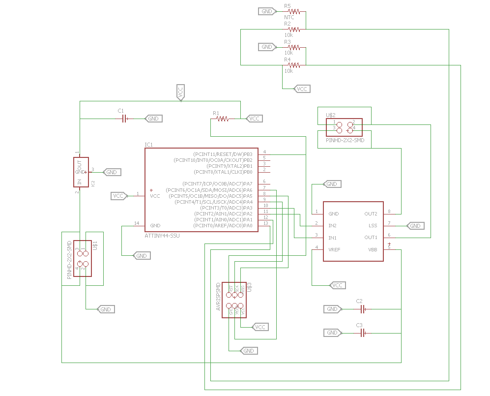
Schematic:
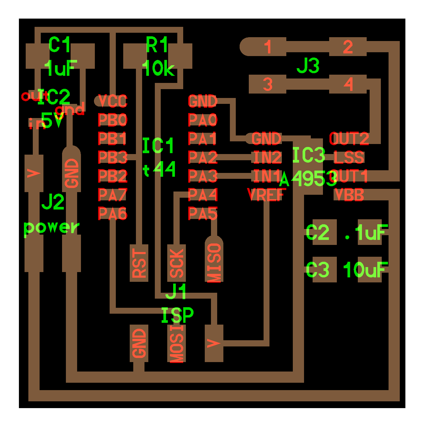
Board:


The w13.c program used for this board was taken from both the hello.temp..45.c and the C program used for the hello.H-bridge.44. With a little help from a friend I was able to come up with a working program. When the temperature gets too high it will activate a 12-volt device. For my final project it will be a 12 VDC fan, but for this week I am using 12 VDC battery powering the board and activating a siren/strobe fire alarm. The video below shows the working board. Since the location of the setup was done on a warm evening, the NTC had to be quickly cooled with a glass of water on the chip. The sound heard at the end of the video is the cat thanking me for turning off the siren.