This
week’s task was to read a micro controller data sheet and get the board
we
created a few weeks back to do something.
The hardest part this week was reading and understating
all the
information in the data sheet. The
programing I found fairly easy since I teach basic c programing for
computers
which is very similar just have more restrictions on how much memory
you use
and that you are reading physical port not just keyboard or file inputs.
The
almost 300 page data sheet for the attiny44 has a ton of information in
it. It is
overwhelming the amount of
information in the sheet. The
data sheet
covers everything from what the pin out is to how the micro works with
the
different function on the pins. For
this
week I found the information on the porta and portb the most useful. There are three register
associated with them
a direction register and the porta for output and the PINA for the
input on the
port. The few thing
I would like to
learn more about is the Analog to digital converter and the timers.
This
week for programing I used both the Atmel studio 7 and Linux with
gcc-avr to
compile the code. Below
is the work flow
for using Linux to compile and program an attiny44 using gcc-avr and
avrdude
with the help of make files.
The
first step for trying to use linux for avr embedded programing is to
install
the required software. For
linux you
need to install avrdude to communicate with the programmer and download
your
code to the board. The
next are all part
of the software to compile the program.
Number one is gcc-avr this is the c cross compiler for
avr, avr-libc and
binutils-avr these are both librarys for the gcc-avr compiler.
To get all these applications I did sudo
apt-get install and
then the name of each item.
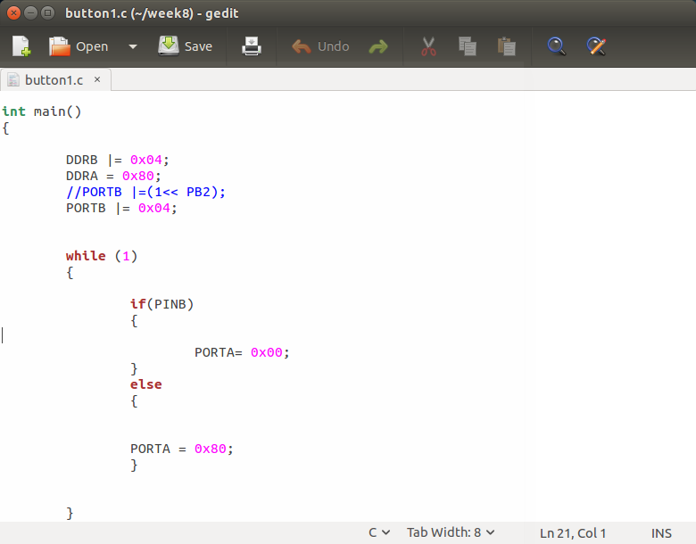
To
start a program you need to make an empty file with a .c extension and
use your
favorite text editor to write your code.
I usually use eclipse but for this week I just used gedit
the write the
few lines of code. To
get started you
need to add a few basic lines the most important part is the main
function. This
function is the first
function the compiler looks for since it has your main code.

The next lines of code I added were the avr library and a library for delay. The delay library allowed me to set a millisecond delay so I can flash my led.
Now I created a while loop that ran forever so the micro always will blink the led. Inside the while loop I turned on Porta 7 using PORTA = 0x80 which sets PA7 high. The next line of code runs a one second delay before turning off the led or setting PA7 to 0 (low).

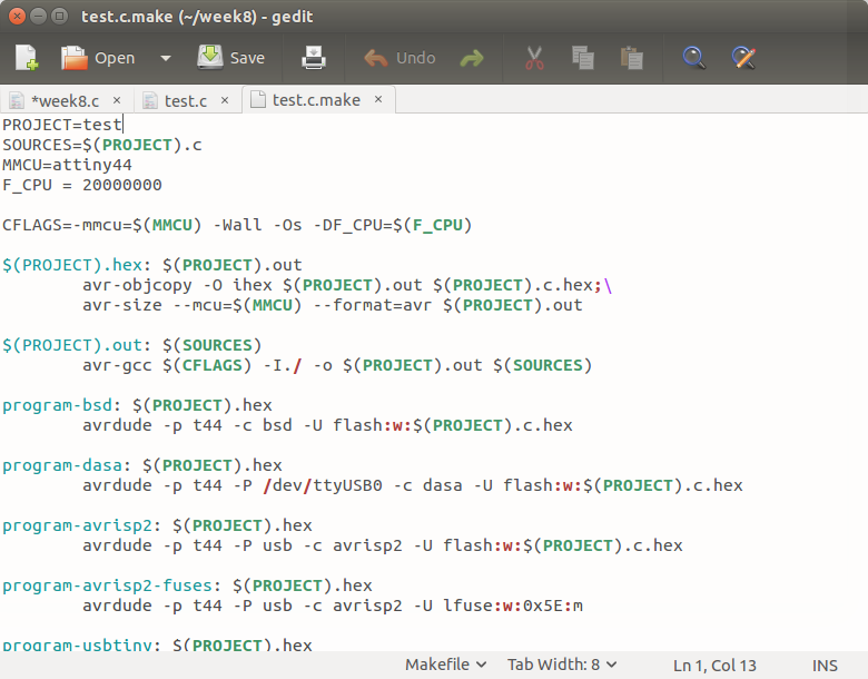
Once the code looks good and you don't think there is any errors it is time to compile. To compile you can either use gcc-avr through the terminal or use a make file. The make file is nice because once you have it made all you need to do is change one to two lines and it can compile and load your program. To get started with the make file I downloaded Neil's Hello44 project and edited the make to run my c code. To make my code run I changed the project = to my file name
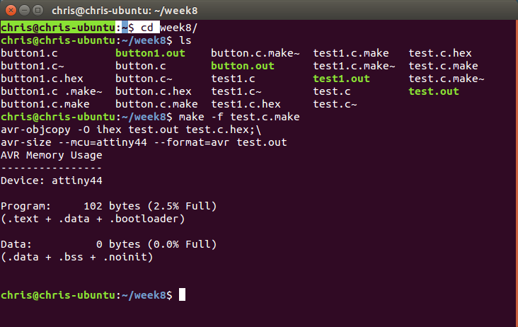
After saving
the make file I ran the command to compile the
code
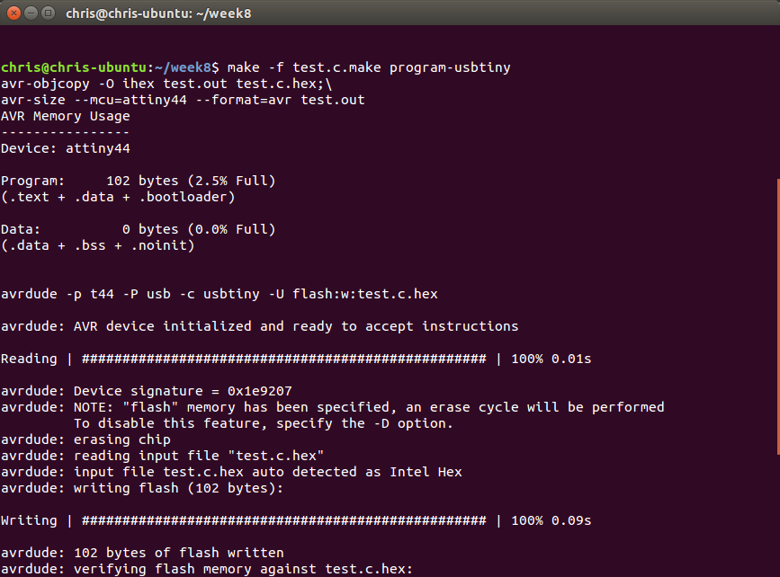
The next step is to use the program-usbtiny-fuses if the fuses have not been set. After the fuses have been set the next command is the program-usbtiny to send the hex file to the micro.
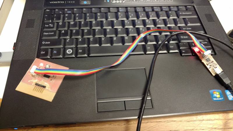
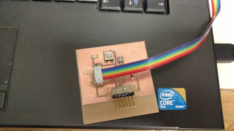
After getting
the led to blink I decided to try to turn on
the led with the push of the button that was added to the board. To do this I had to set
port b 2 to an input
and make sure the pin was tied to VCC internally so it was not floating. This took a few tries but
finally got it to
work.


Once you start atmel studio 7 you need to create a new
project.

Select GCC C executable project and then name it something
meaningful.

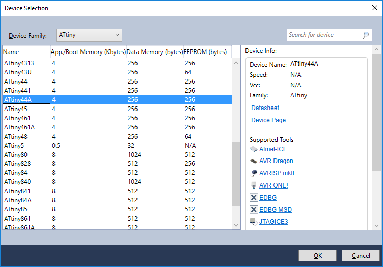
Once you click ok this screen will open and you will have to
select your product you want to program.
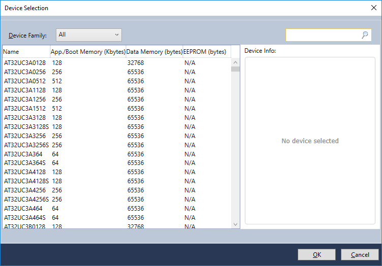
In this case we will select attiny family and then attiny
44a. In the right window it shows all of
the features availed to you like wire debug and what tools are supported like
the atmel ICE debugger.
Once your device is selected it will open to a blank C file
so you can add your code.

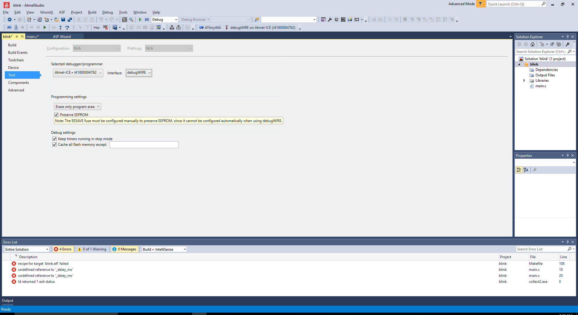
Once you add you code you need to tell it what tool you are
using in this case the atmel ice.
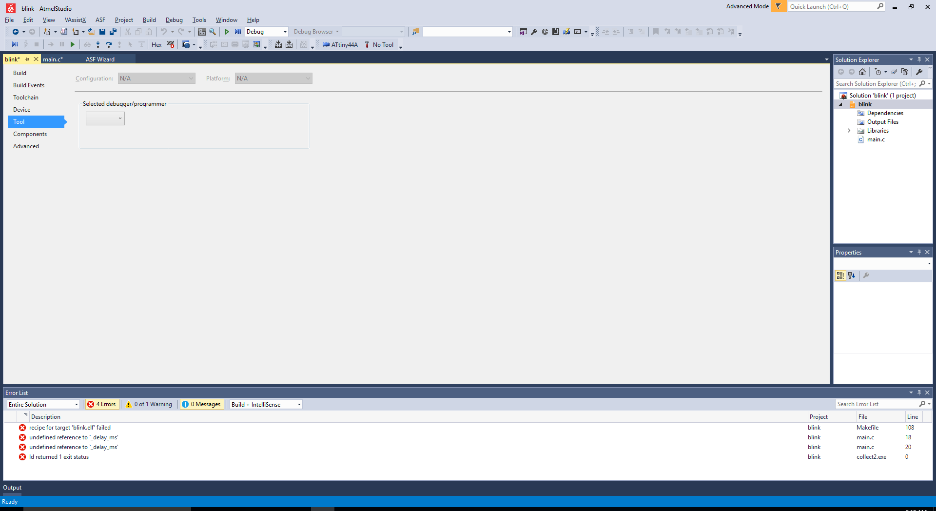
There are two options when the ICE is selected on is ISP
which is the normal programing way.

Or you can select debugWIRE that is what I choose. It allows you to set break points and see
what is happing in your code.
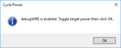
When you first click on the debug this message will appear. You will have to click yes to enable the
debugWire be setting the DWEN once this is set you have to have the program
disable it before you can use the normal ISP programmer so you have to be
careful.

Once you click yes you have to power cycle the board and now
you are in the debug mode.
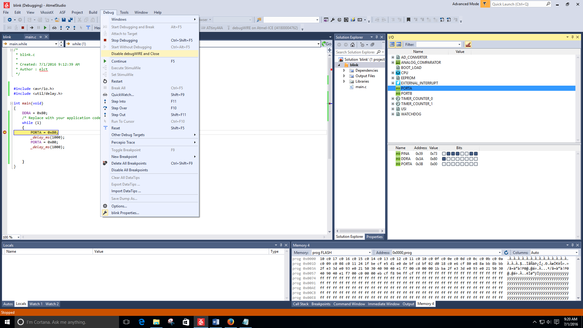
If you click on a line of code you can add a break point to
stop your program and then you can look at all of the registers and ports to
see what is happening.

Once you are done with debugging you have to make sure you
choose disable debugwire and close from the debug menu so that you can use your
normal ISP programmer if needed later.
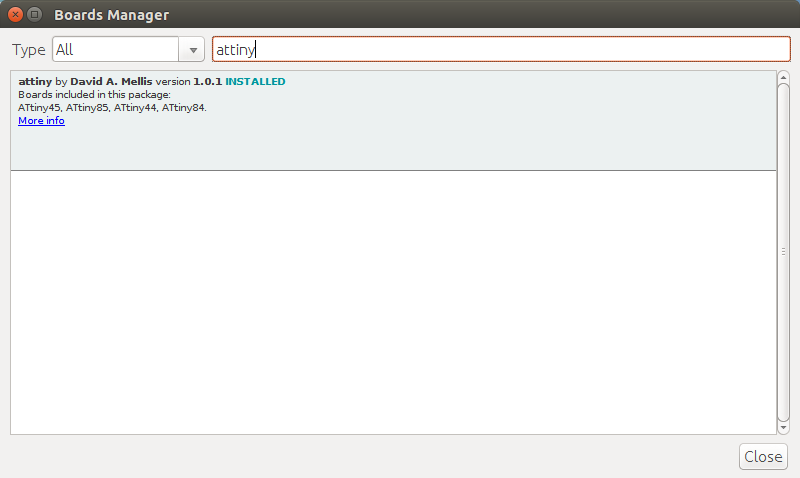
Once the adrunio IDE is installed and opened to get it to
work with the attiny’s you need to add boards via the board manager.

If you search for attiny it will bring up the attiny cores
from David Mallis
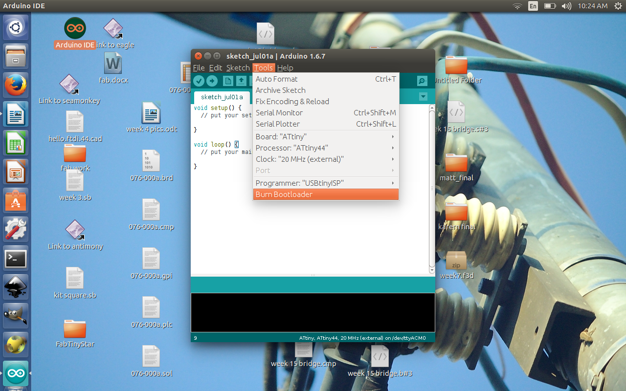
Once the attiny cores are installed you can select that and then what attiny and then what clock speed and the programmer. In this case it will be the attiny 44 at a external 20 MHz clock and using a USBtinyISP that we made in an early week.
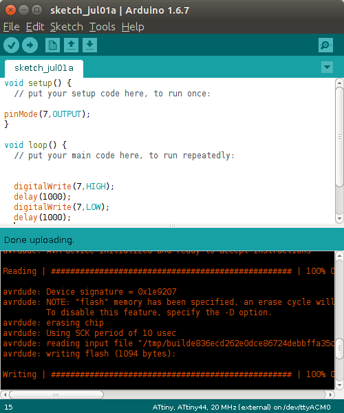
When using the Arduino IDE the code is very C like and is
based on that and Wiring. Instead of
having an int main there is a setup function and a loop function. The setup only gets run once at power up and
the loop function keeps running over and over.
To make a simple blinking led program you need to set the pin to be an
output or input and the pinout is a bit different then the data sheet and in
this case I will be using pin7 or PA7. To
turn the pin on the digitalWrite function is used and you tell it what pin and
either to be HIGH or LOW. The HIGH and
LOW are keywords that have a value of 0 or 1.
Once all your code is written it time to load the code to the board you
can do this by using the upload button. If
everything is ok it will program and you board should work. This IDE is very easy to use and easier to
understand what is happing but there is a lot of overhead compared to the
native C programing via avrggc or atmel studio.