This week’s assignment was to make something big on the
shopbot or similar machine. I decided to
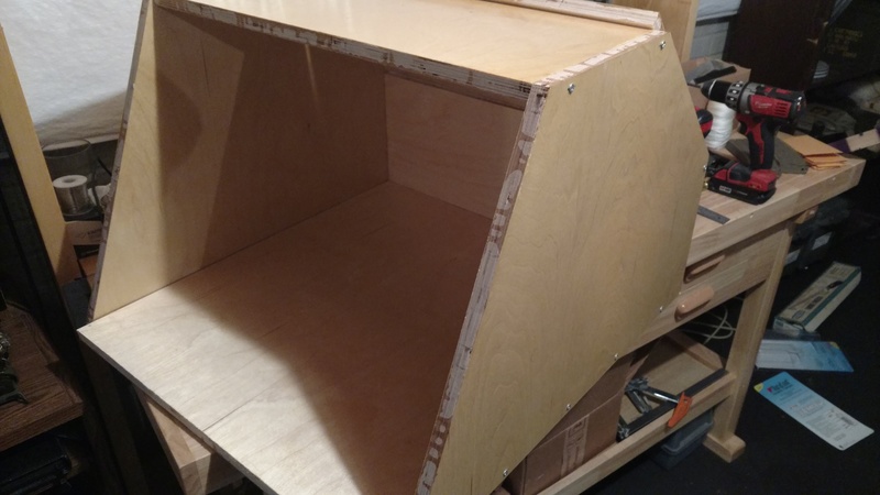
make a table top spry booth. To start my
design I used Autodesk’s fusion 360 to create the parts and make a 3d
rendering.
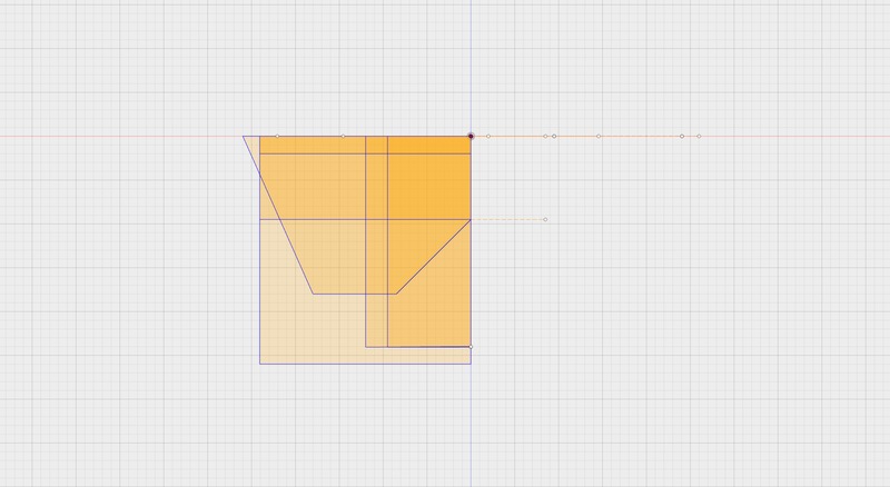
In fusion 360 I first started by creating a sketch of all
the parts.
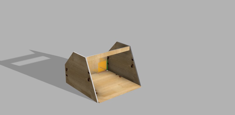
Once I had all the parts I made a 3d model and render so I
could see how everything fits.
In fusion 360 you are able to export the sketches to dxf
files. After all of the files were
exported to dxf I had to being them into Aspire to make the shopbot tool
paths.
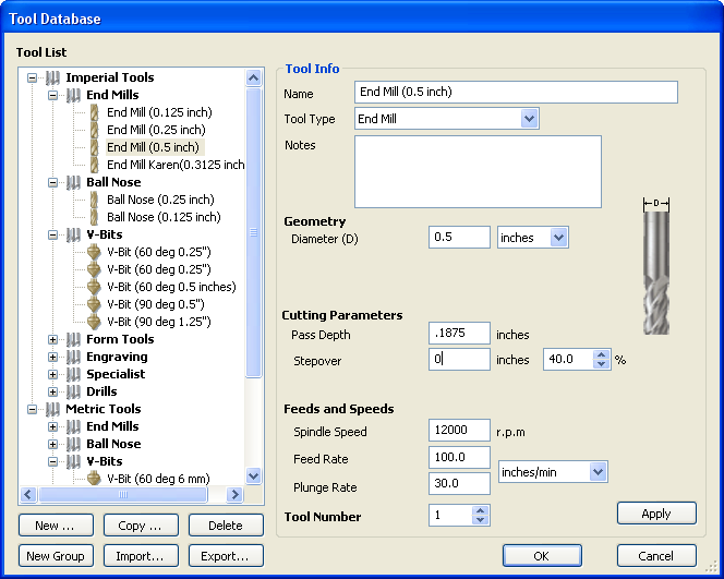
In aspire there was a few thing that needed to be set up. The first and main one is the tool, you need to select what tool you are going to use and then make sure the speeds and feeds are set for the material you are cutting. To cut out my design I used a half inch end mill with a rotation speed of 12000 rpm and feed rate of 100 inch pre min, the plunge rate of 30 inch pre min and the pass depth was set to .185 inch. Now that the tool is setup you can have the programs generate the tool path and then save it as a shopbot file for cutting.
Once the tool path is created it time to setup the material
on the shopbot and then zero all the axis.
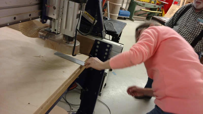
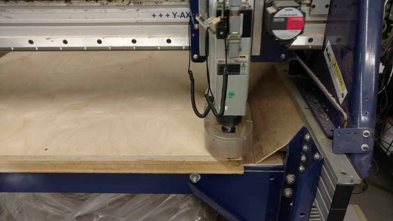
The pictures below show Karen setting up her project I was there to
learn the steps on how to do it and take pictures for her. There was no one around to take pictures of the
set up but I do have pictures of the cutting process.
The first step is to zero the x and y axis. This is done by positioning the tool at your zero point and setting the machine settings to zero. After that you can zero the z axis for this we have a metal plate that make contact with the tool for the zero.
Now that everything is zeroed you can run the tool path with
an offset so it runs above the material to make sure it runs. After that it’s time to warm up the spindle
this can take some time especially if you are the first person to use the machine
that day. To do this you run the spindle
at a low speed for a few minutes and then add some speed like 2000 more rpm
from where you were at and then let it run for another 5 minutes and this process
is continued until your final speed is reached.
Here is the zero of the x and y axis
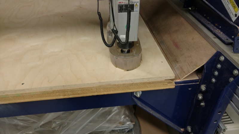
The now for the cutting
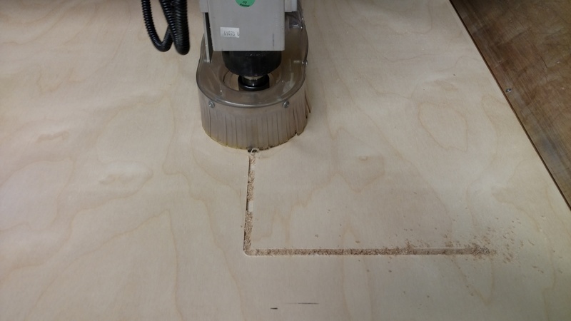
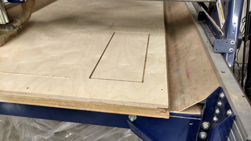
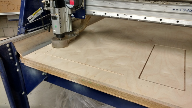
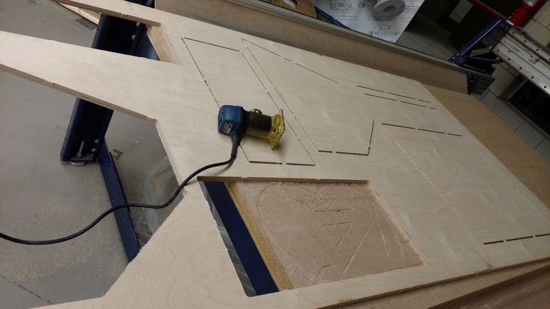
After all the pieces were cut I had to take them out. I put small tabs in when I generated the tool path to keep the parts in place while machining so I used a hand held router to remove the parts.
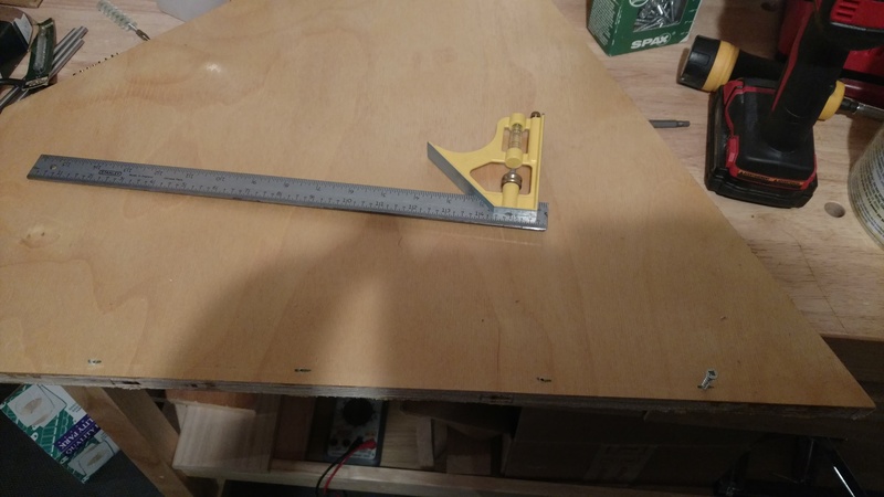
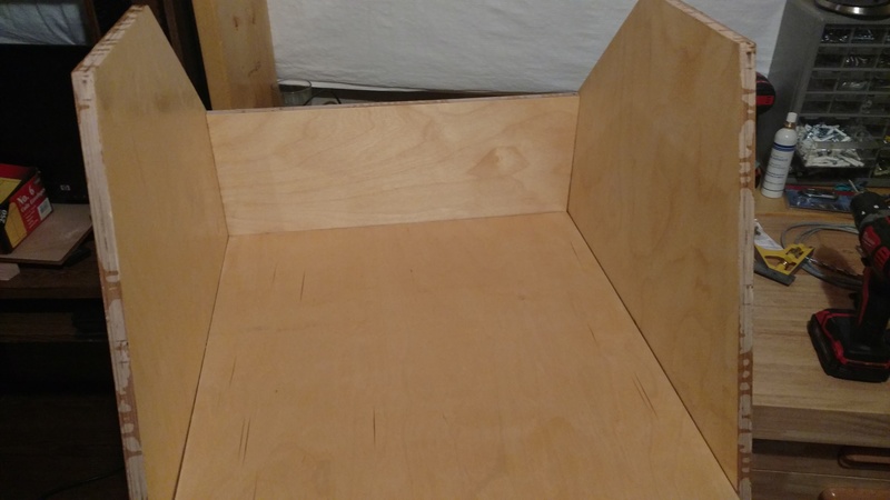
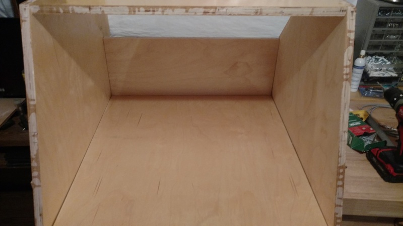
Once all the pieces were cut I sealed them with some polyurethane to protect the wood and then it was time to assembly. First I laid out the screw placement I did this by hand but could have used the shopbot to drill the holes but at the time I did not know where I wanted all of the drills.
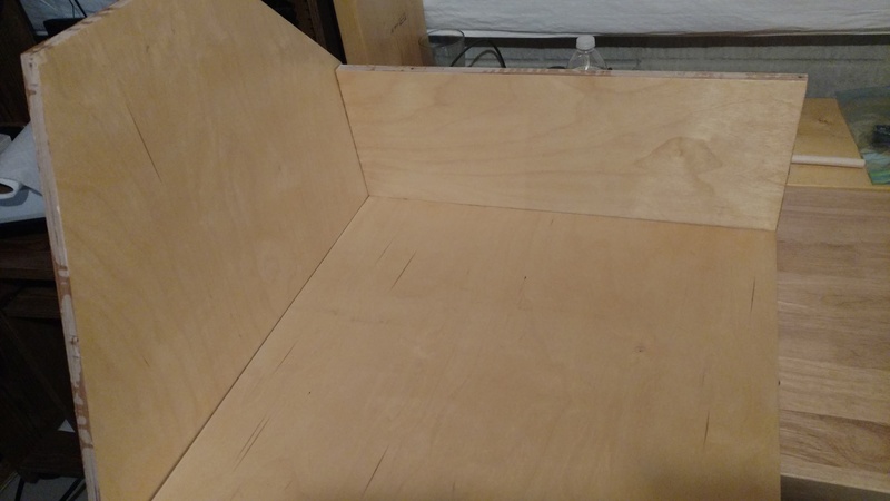
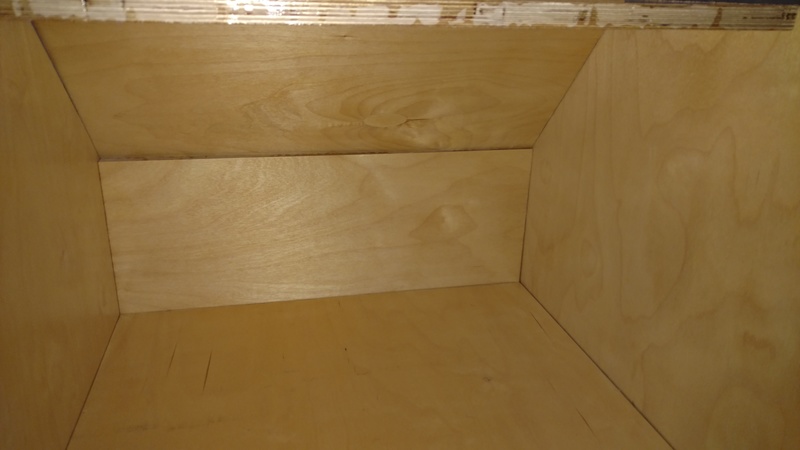
After that it was assembly time.
One of the last parts is I need to buy a good high volume blower to exhaust the paint fumes out. I am currently looking at a few but they cost $150 to $200 so I have to wait a bit to get one. I also have to mount a furnace filter to help catch some of the over spray. Once I have the rest of the parts I plan to add some leds for light.