The 3d scanner
we have at the college to use was the
Go!SCAN 50™ from
Creaform.
The table below
is for both the go scan 20 and 50 we have
the Gocan 50 but it is the previous gen so it will not map the color.
|
|
Go!SCAN 20™ |
Go!SCAN 50™ |
|
WEIGHT |
930 g (2.05 lbs.) |
950 g (2.1 lbs.) |
|
DIMENSIONS |
154 x 178
x 235 mm (6 x 7 x 9.2 in.) |
150 x 171
x 251 mm (5.9 x 6.7
x 9.9 in.) |
|
MEASUREMENT
RATE |
550,000 measurements/s |
|
|
SCANNING
AREA |
143 x 108 mm
(5.6 in x 4.3 in) |
380 x 380 mm
(15 in. x 15 in.) |
|
LIGHT
SOURCE |
White light
(LED) |
|
|
RESOLUTION |
0.100 mm (0.004 in.) |
0.500 mm (0.020 in.) |
|
ACCURACY |
Up to 0.100 mm
(0.004 in.) |
|
|
VOLUMETRIC ACCURACY* |
0.300 mm/m
(0.0036 in./ft) |
|
|
POSITIONING
METHODS |
Geometry
and/or color and/or targets |
|
|
STAND-OFF DISTANCE |
380 mm (15 in.) |
400 mm (15.75 in.) |
|
DEPTH-OF-FIELD |
100 mm (4 in.) |
250 mm (10 in.) |
|
PART
SIZE RANGE (RECOMMENDED) |
0.05 – 0.5 m (2
– 20 in.) |
0.3 – 3.0 m (1
– 10 ft) |
|
TEXTURE RESOLUTION |
50 to 250 DPI |
50 to 150 DPI |
|
SOFTWARE |
VXelements |
|
|
OUTPUT
FORMAT |
.dae,
.fbx, .ma, .obj, .ply, .stl, .txt, .wrl, .x3d, .x3dz, .zpr |
|
|
COMPATIBLE SOFTWARE |
3D
Systems (Geomagic® Solutions), InnovMetric Software (PolyWorks),
Dassault Systèmes (CATIA V5 and SolidWorks), PTC
(Pro/ENGINEER), Siemens (NX and Solid Edge), Autodesk (Inventor, Alias,
3ds Max, Maya, Softimage). |
|
|
CONNECTION STANDARD |
1
x USB 2.0 |
|
|
OPERATING TEMPERATURE RANGE |
5-40 °C
(41-104 °F) |
|
|
OPERATING HUMIDITY RANGE (NON-CONDENSING) |
10-90% |
|
The first thing to be able to scan with this system is you need to prep the item with reflective dots for references.
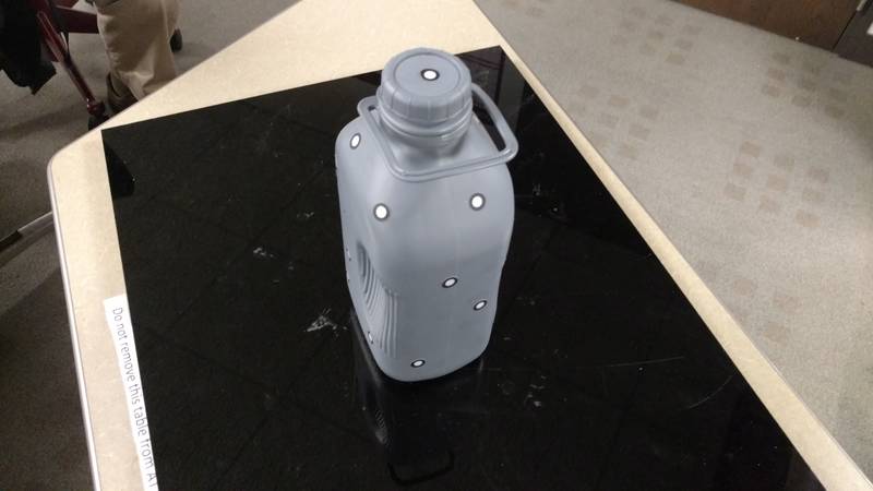
After the item
was prepped the scanner was hook up via usb
and the software was started.
VXeleamints is the scanners software it has a blank screen
and when the
button of the scanner is pressed the software registers the item. When scanning you need to
rotate and scan all
side, the dots help for referencing when the item is moved. When every part is scanned
and the model in
the computer looks complete and has very little to no holes the
scanning
operation is complete and then you can go to the next step of clean up.
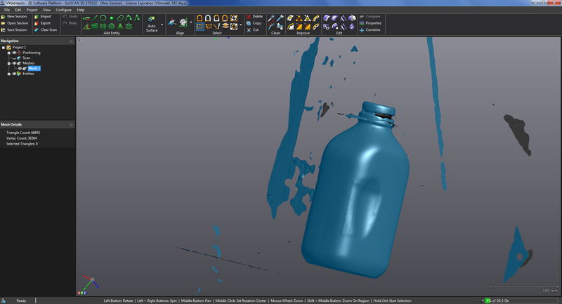
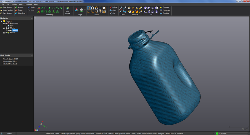
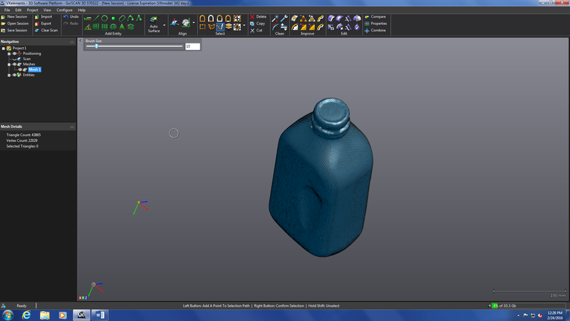
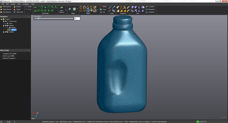
The picture above is the model generated with a lot artifacts. The next step is to clean the model up with the tools in the software. There is a tool that you can highlight items you do not want and delete them. You can also select the main item and inverse to get rid of the artifacts.
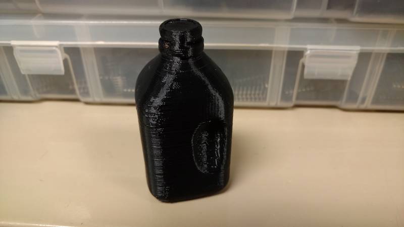
After the cleanup there was a thin handle on the milk bottle that I scanned and it did not full come out so I got rid of that piece.
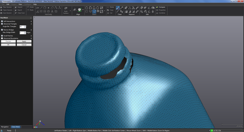
After all of
that you have the fill any holes that were left
in the model this program has a built in heal button that will do its
best job
to fill the holes. In
this case I had
very few holes and they were small so the program worked very well but
it does
not always do that some manual filling may be needed.
After all the holes are filled like the one in the picture above and the object looks good it usually has too many triangles to import into soildworks or other programs so you need to decimate the object to reduce the number of triangles. In this software there is a button to decimate and it has a few options one is how many is the max number of triangles and it also show how many there are at this time. In this case I forced it to be around 18 thousand.
After all the
work you can export the file as a stl so you
can import it into a 3d printer software and print it.
I printed my scanned object but at a very
small scale.
Week 5 3d scan Bottle by crohal on Sketchfab
In the fab lab at LCCC we have two 3d printers one is a MakerGear M2 the other is a Stratasys Dimension 1200es. Below is what we have come up with for the tolerances of each machine.
MakrerGear:
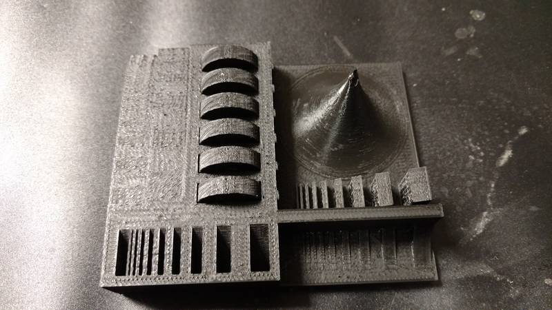
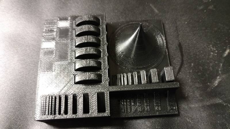
Below is the
test part that a former Fab Academy student
made for testing tolerances. Both
machine
did ok but the parts that were supposed to be moveable were not.
MakerGear M2
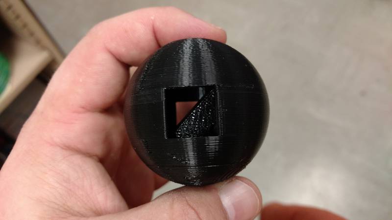
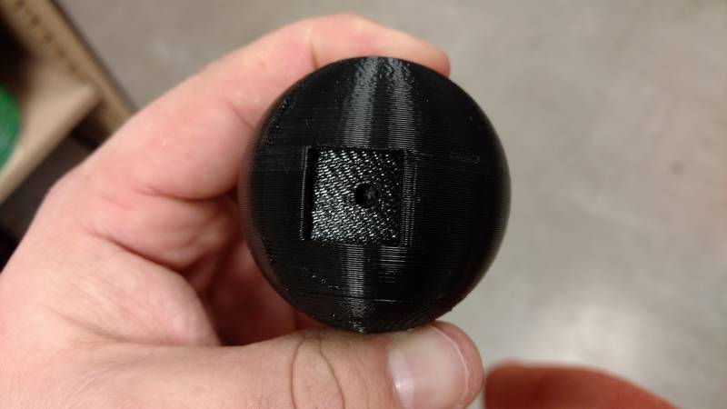
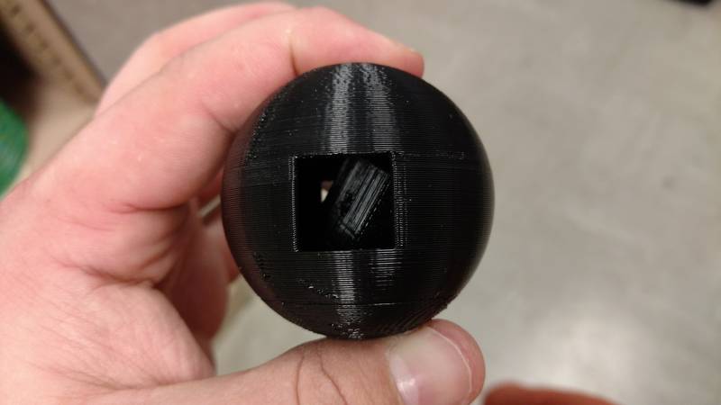
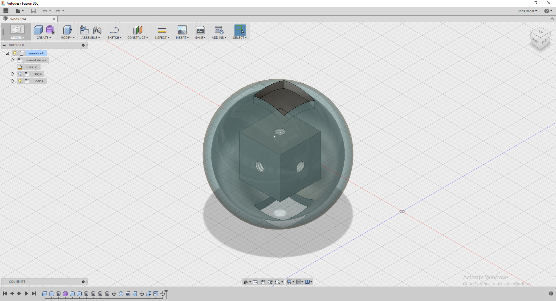
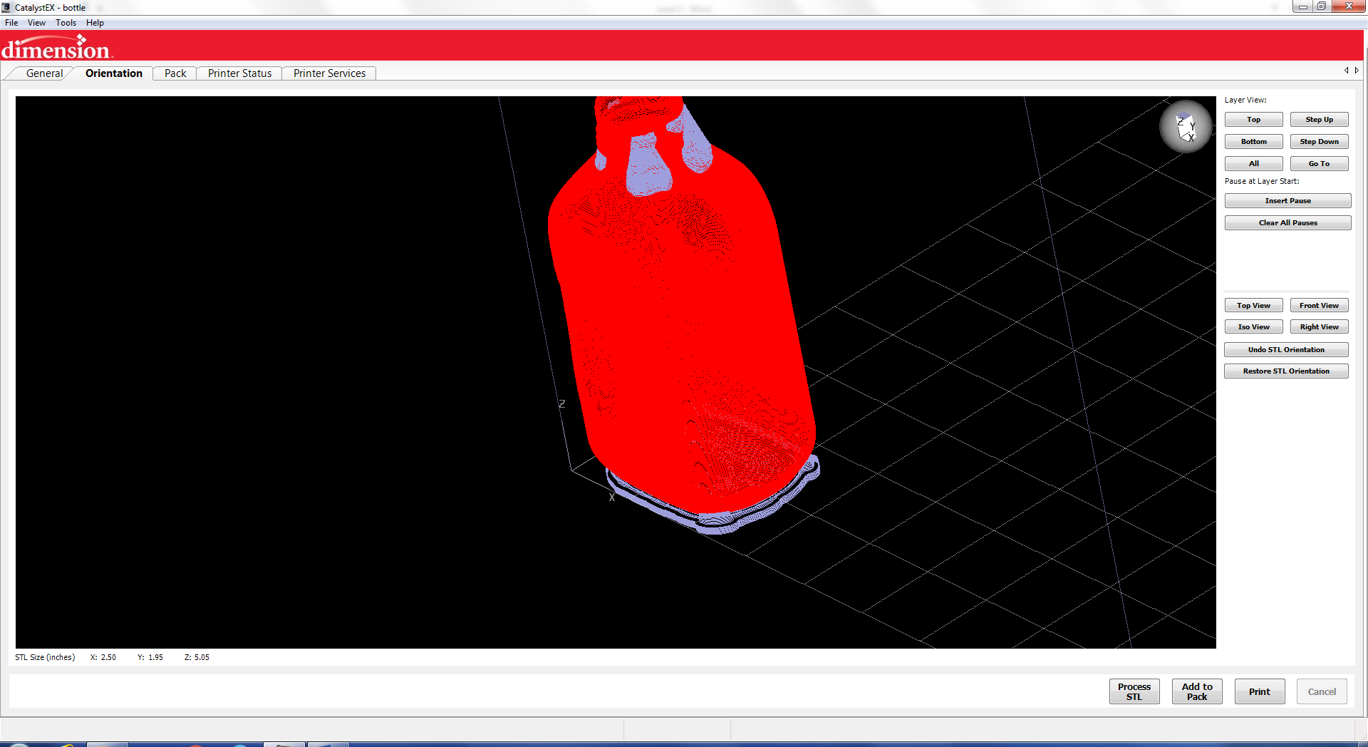
For my 3d printed part that cannot be made subtractively I decided to make a cube with holes on each face and then put it inside of a sphere that has two squares cut out that are smaller than the cube inside. I used Autodesk Fusion 360 to make the object and then printed it out on the Dimension 1200es using the catalyst software. In the below screen shots for the printer software I used the bottle that I scanned for the step thru but the process is the same for the sphere I created.
Week5 Add by crohal on Sketchfab
The first step is to load your stl.
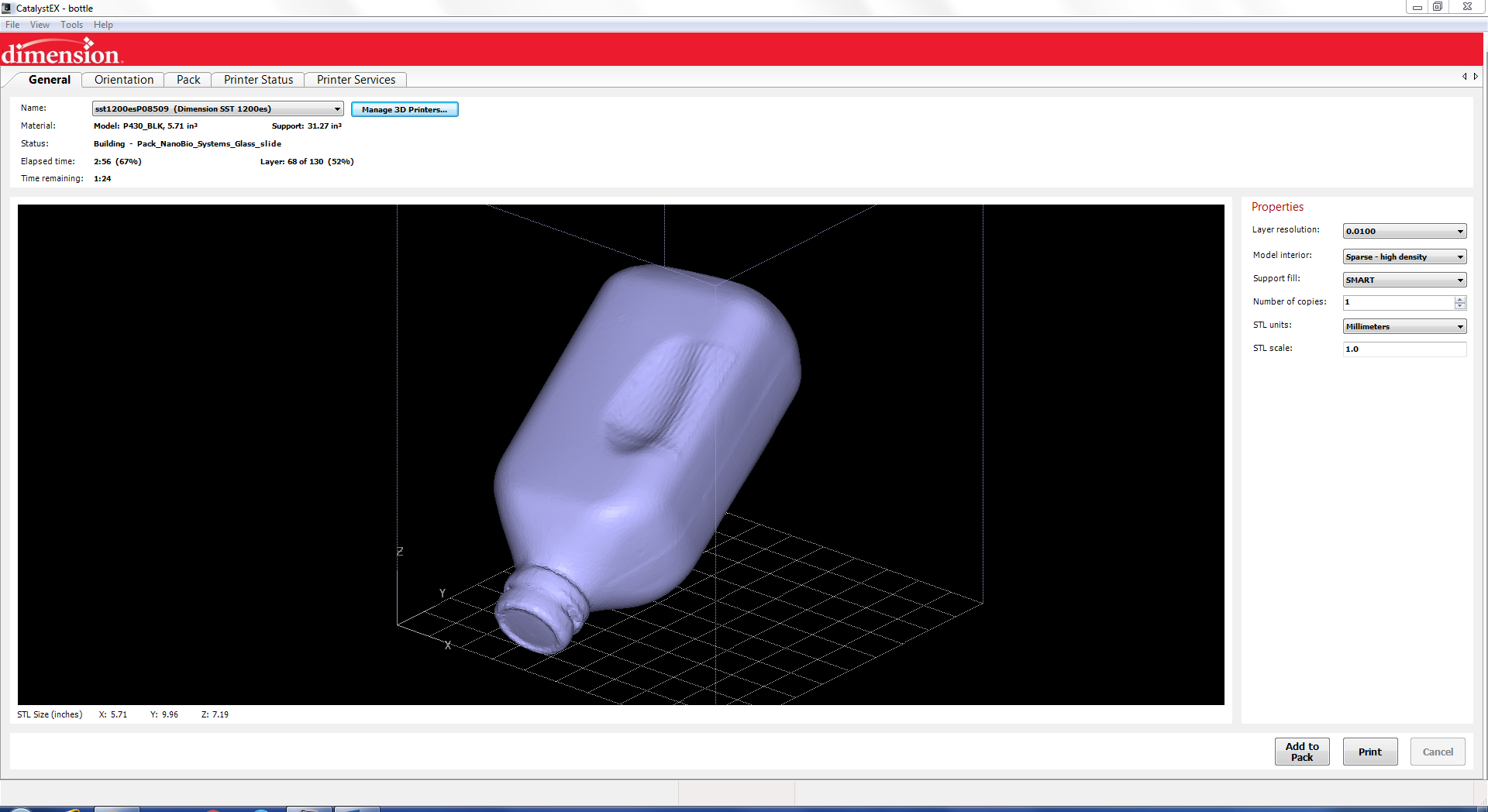
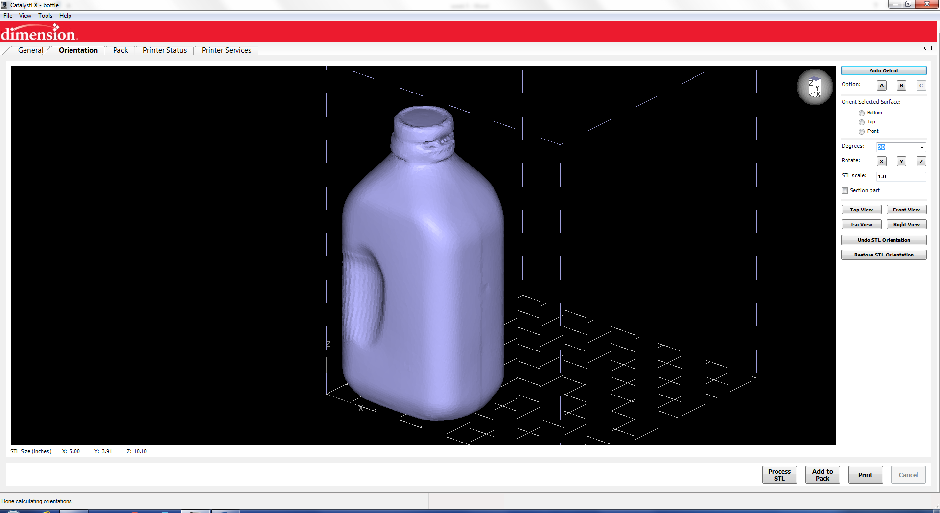
Next you can oriented and change how the printer prints like if it is solid or is spare low density.
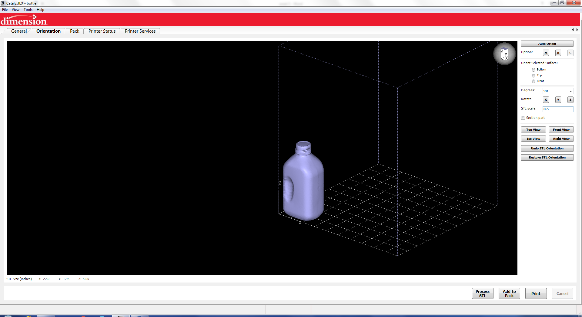
Then I scaled it to make a smaller version
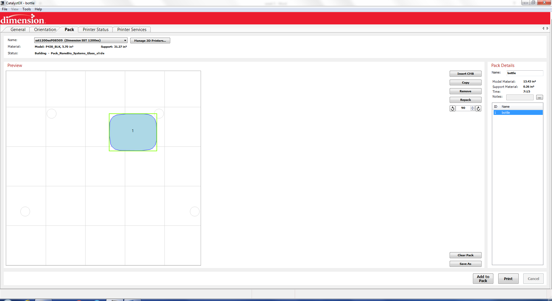
The next step
is to let the software process the stl to
generate the tool paths.
After the toll
paths are created you can add it to the pack
and then print.
After the part is printed it must soak to dissolve the support material