This week’s
assignment was to create an ISP so we can program circuits later in the
class. There was a
few different versions
on the lecture page I went with Zaerc
because
I liked the features of it. The
target
power led and the data led are nice to see if the programing is doing
its
job. The other main
reason I choose this
design was the very nice and helpful website that steps you thru the
whole project. There
was only two big issues this week the first
was when Karen and I tried to cut a board it cut out but some of the
traces
were gone. After
reading all of the
milling documentation on the website we learned you had to change the
tool size
to a smaller diameter to have the software calculate some of the paths. The other problem was when
I tried to use the
programmer it would not send the code.
After some troubleshooting and use of an oscilloscope I
saw the data
being sent but then stopping so I decided to try and reset the fuses
from the
last step. This
work and the programmer is
fully functional
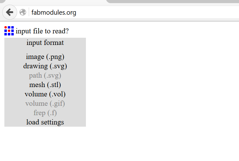
The first step to using the fab modules is to load the settings for the local lab for communication and other settings.
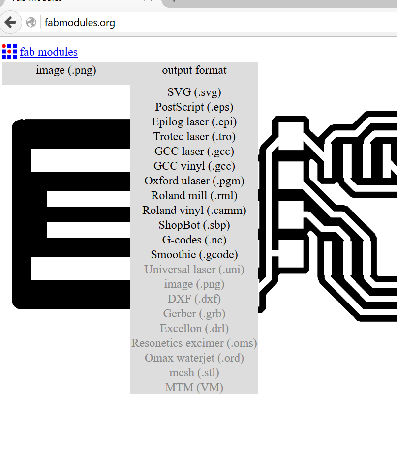
After the setting are loaded you need to select an input file format and in this case it is a .png. The png that you load first is the top traces. After the file is loaded you need to select an output format in this case it was the roland mill.
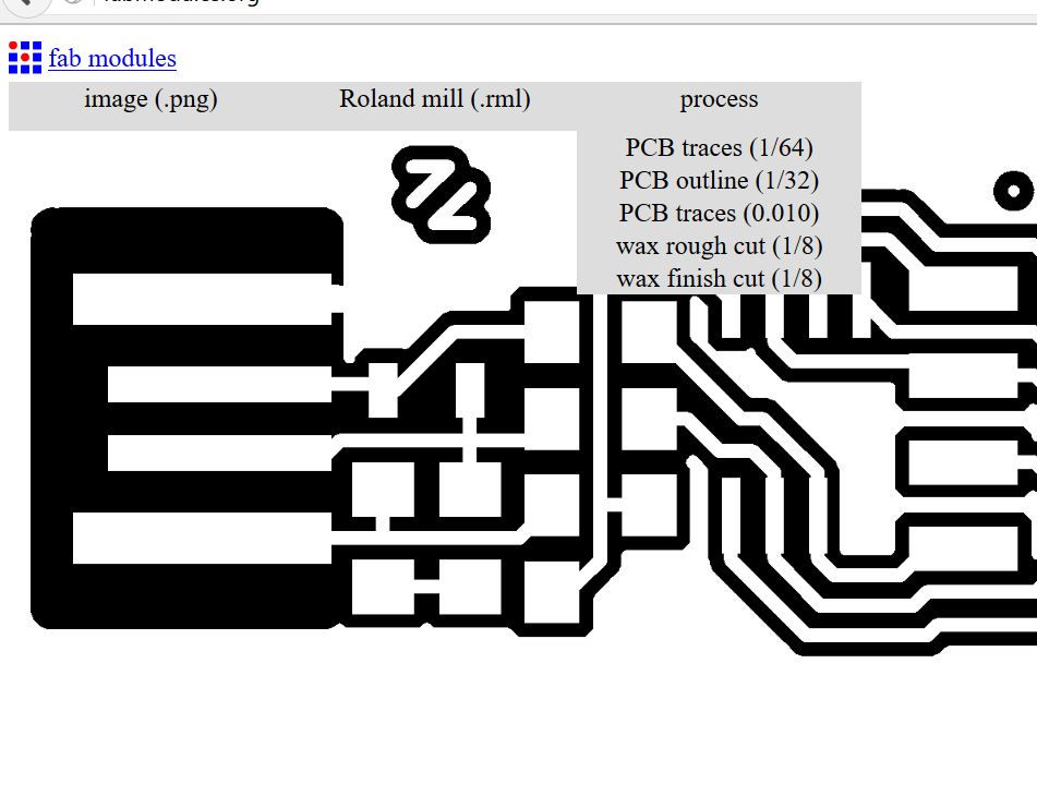
After the Roland mill was selected you need to choose the process and since it is the top of the board you need to select PCB traces (1/64).
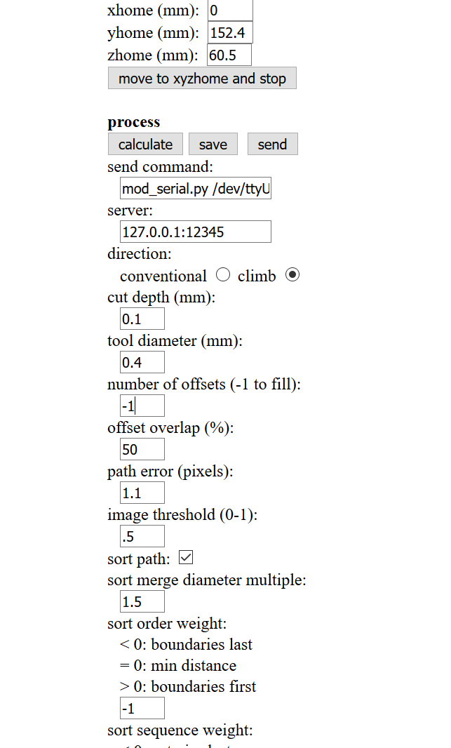
Once the file
and the process has been selected there are a
few settings you need to change the one main one is the number of
offsets. The number
of offsets this determines how
many times the bit routes out around the trace by using -1 it will
remove all
the copper that is not needed.
After the
setting are enter you can click the calculate
button and it will generate the tool path.
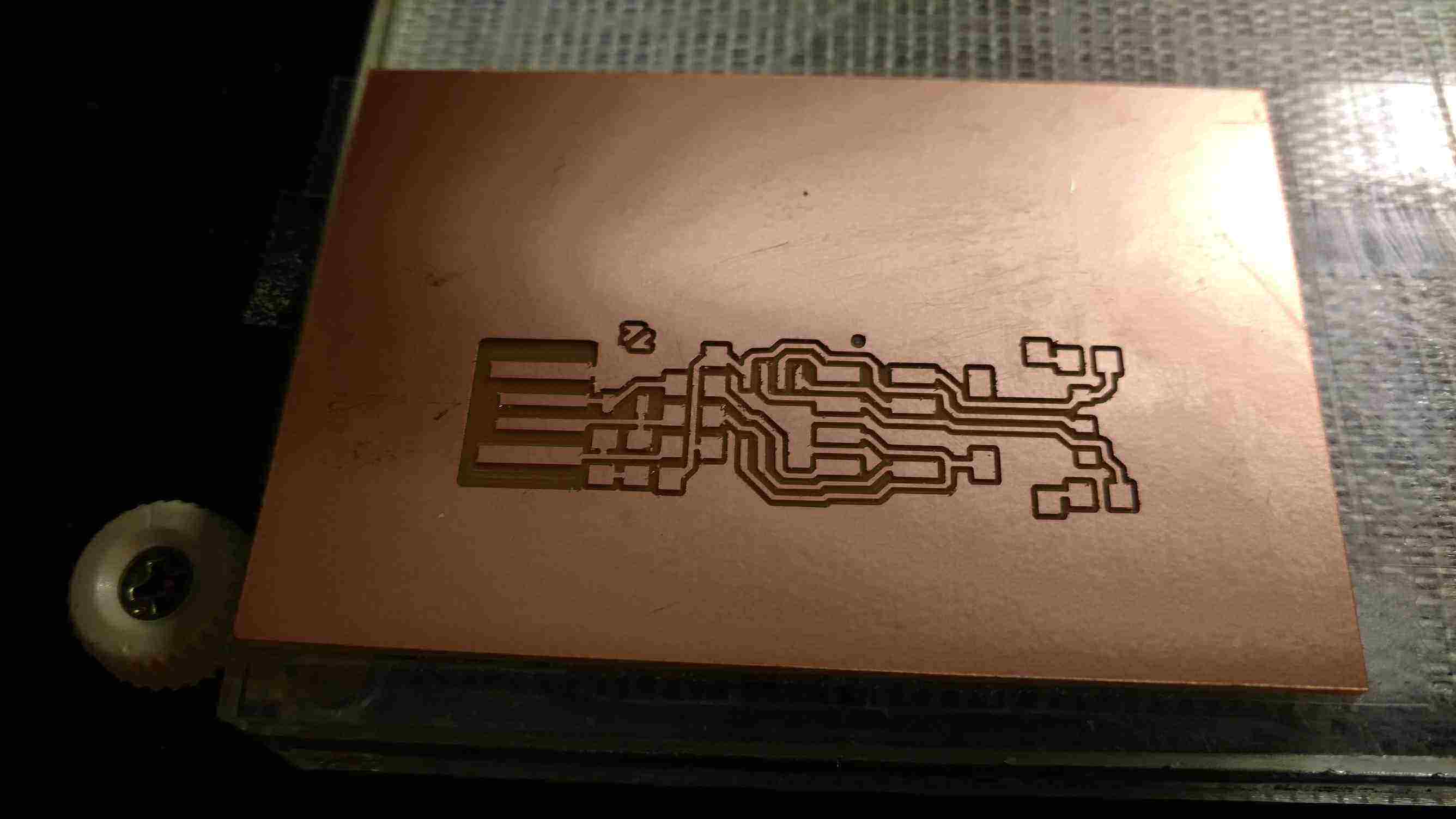
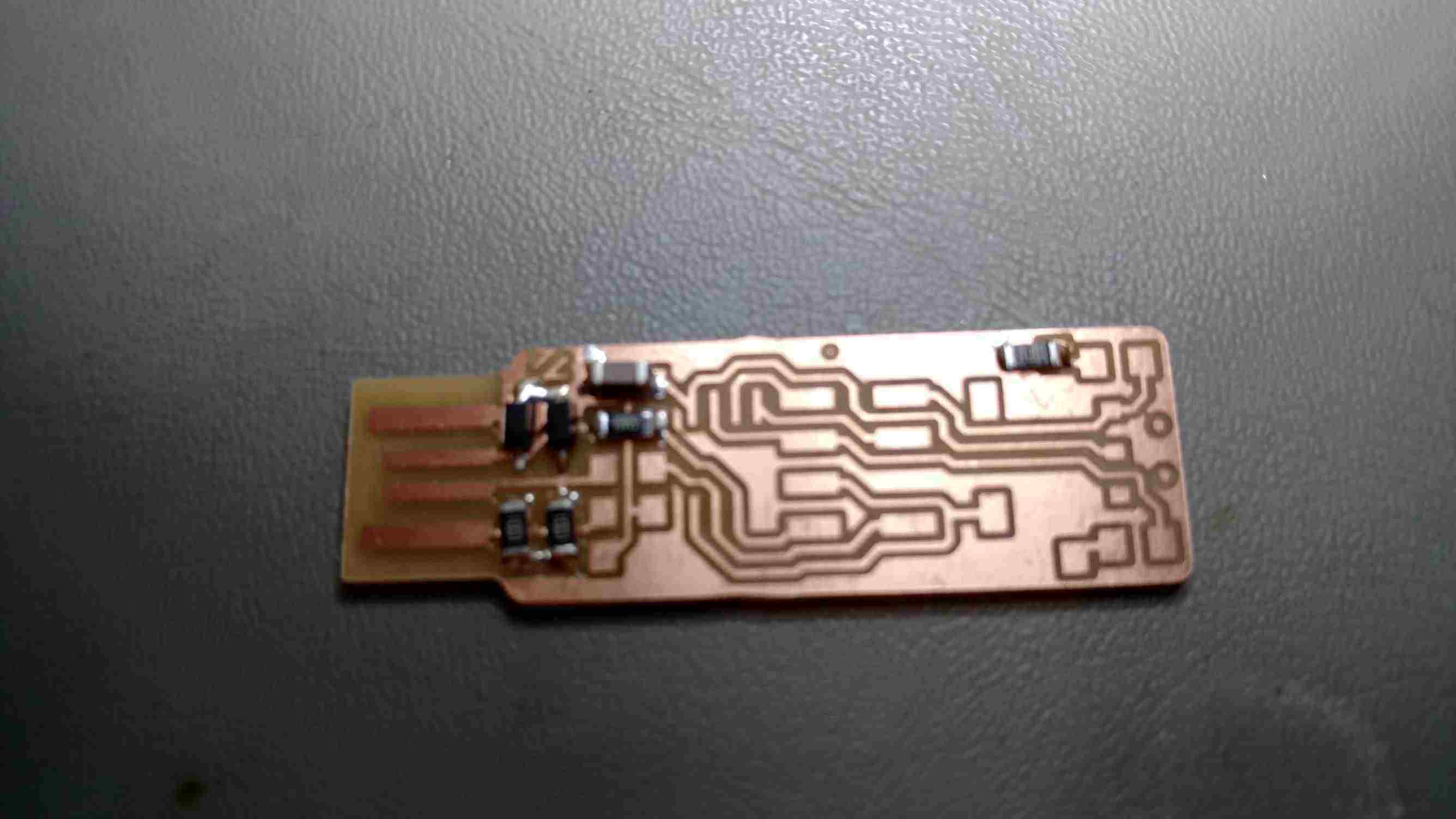
You need to check to make sure that all the traces have
come out. The below
picture show that the default
setting for the tool width does not work so I had to change it to .35
from
.4mm.

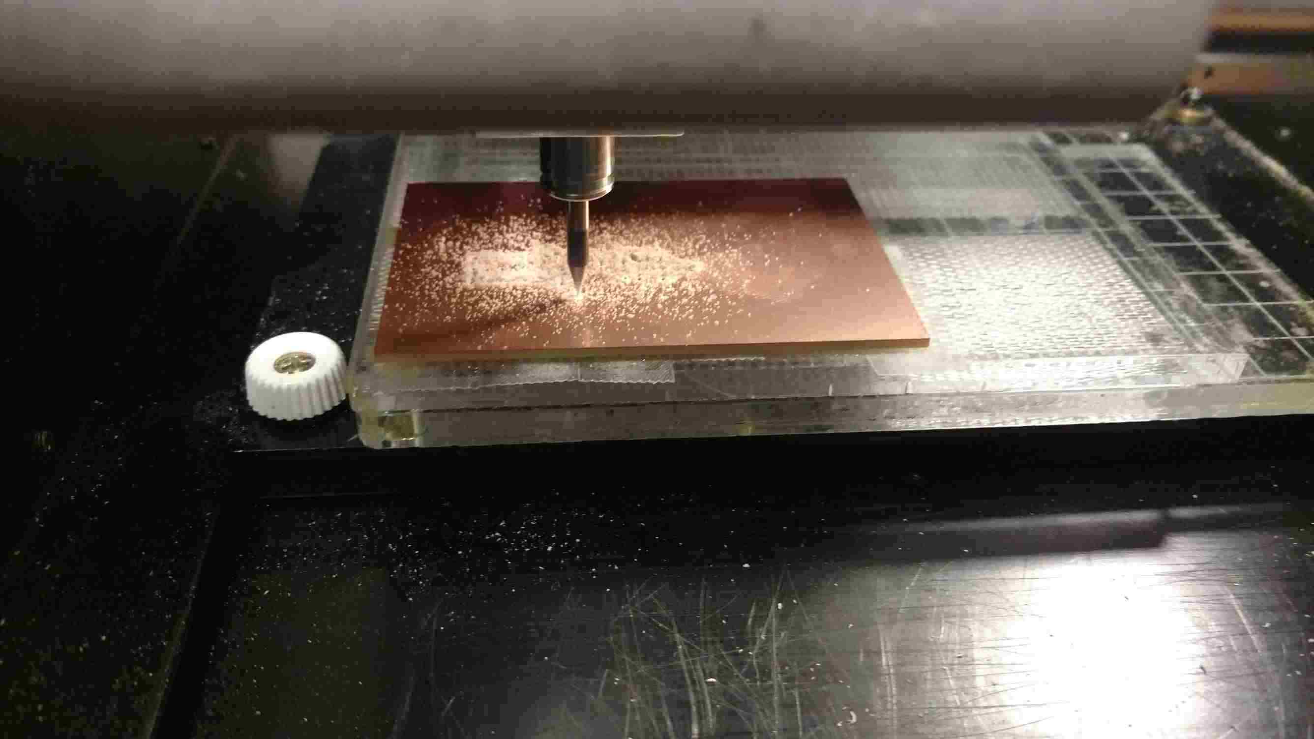
Once the traces
have been generated we need to setup the
mill. Step one is
to mount the material
by using double face tape.
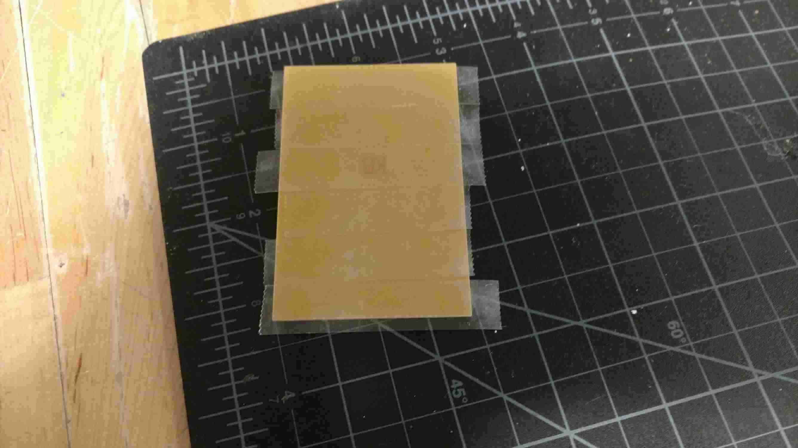
Step two is to place the board close to the origin of the machine.
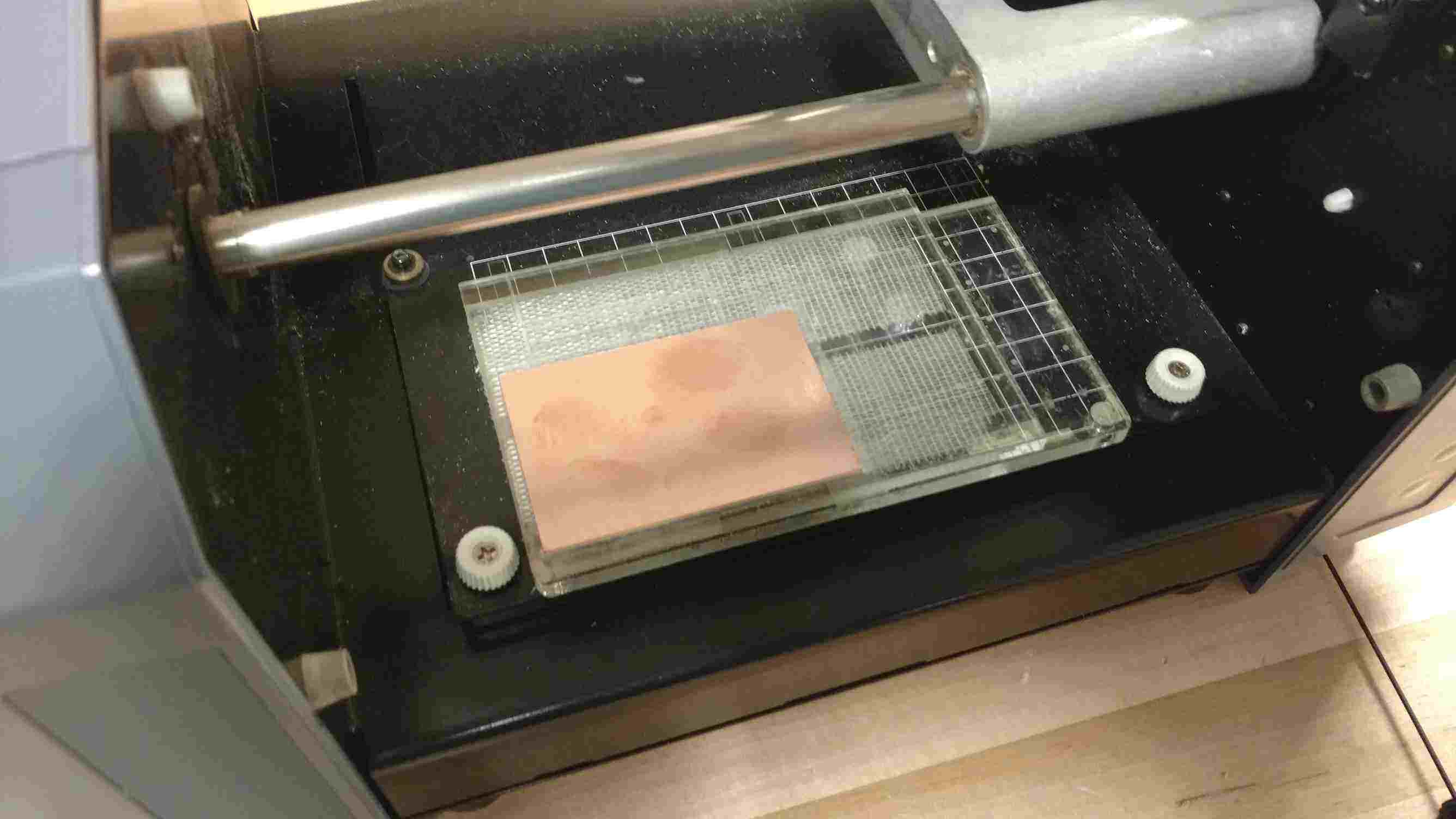
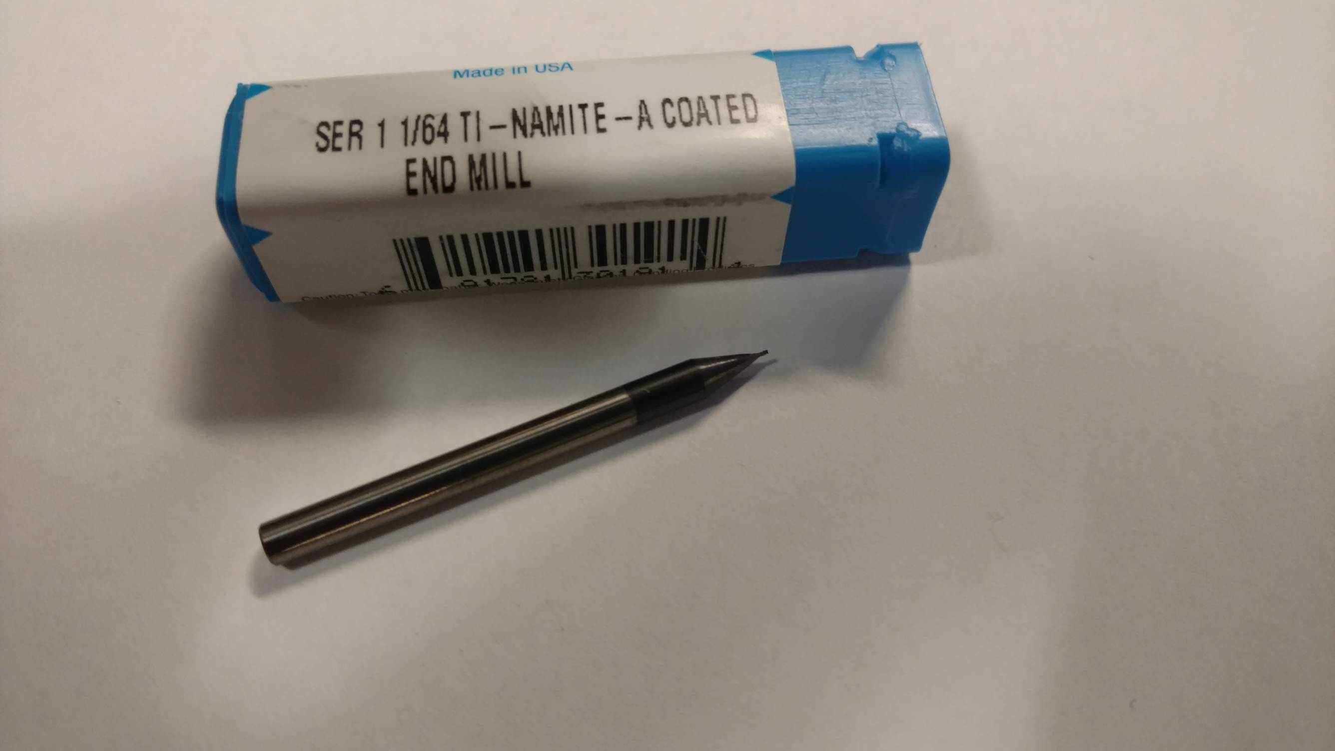
Once the board
is mounted the 1/64 end mill is selected and
inserted in the spindle. After
the end
mill is in you need to adjust the tool height by moving the head to a
blank
spot on the material and lowing the head to close but not touching
after that
you loosen the set screw for the end mill and gently lower it and hold
it on
the surface. The
next step is to tighten
the set screw and get ready to send the data.
After the tool and tool height is set we can send the path to the machine and watch to make sure nothing goes wrong.
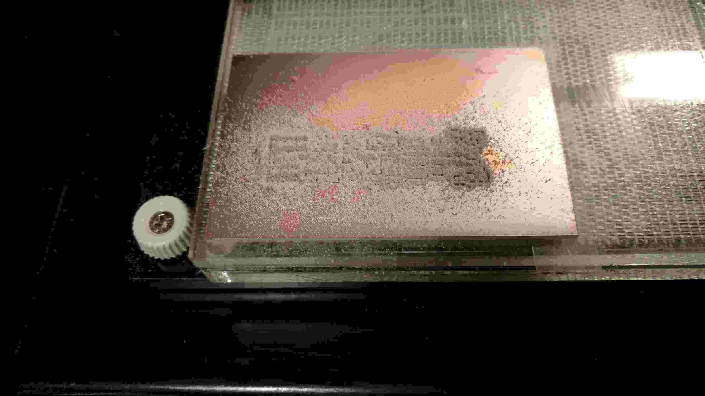
After the top
is milled it needs to be cleaned to remove the
residue from milling this is easily accomplished with a small vacuum.
The last step is to use the fab modules and use the outline picture to generate a tool path to cut the board out with any luck you should now have a board.
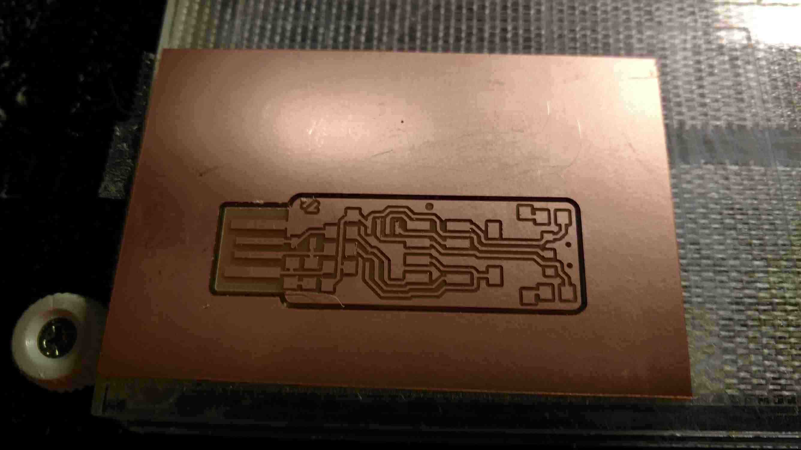
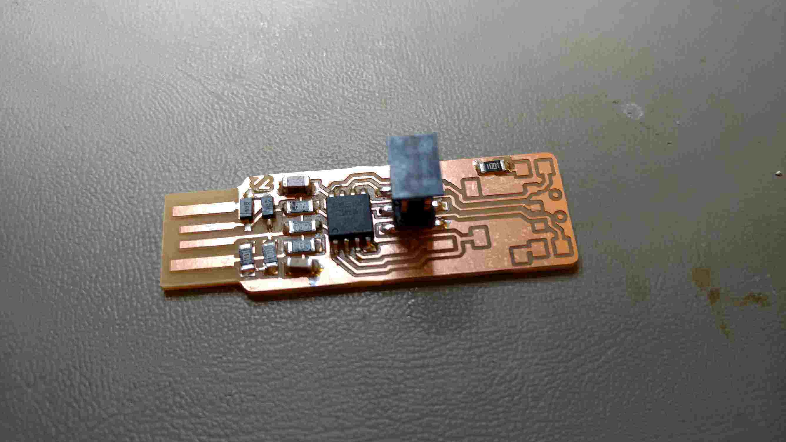
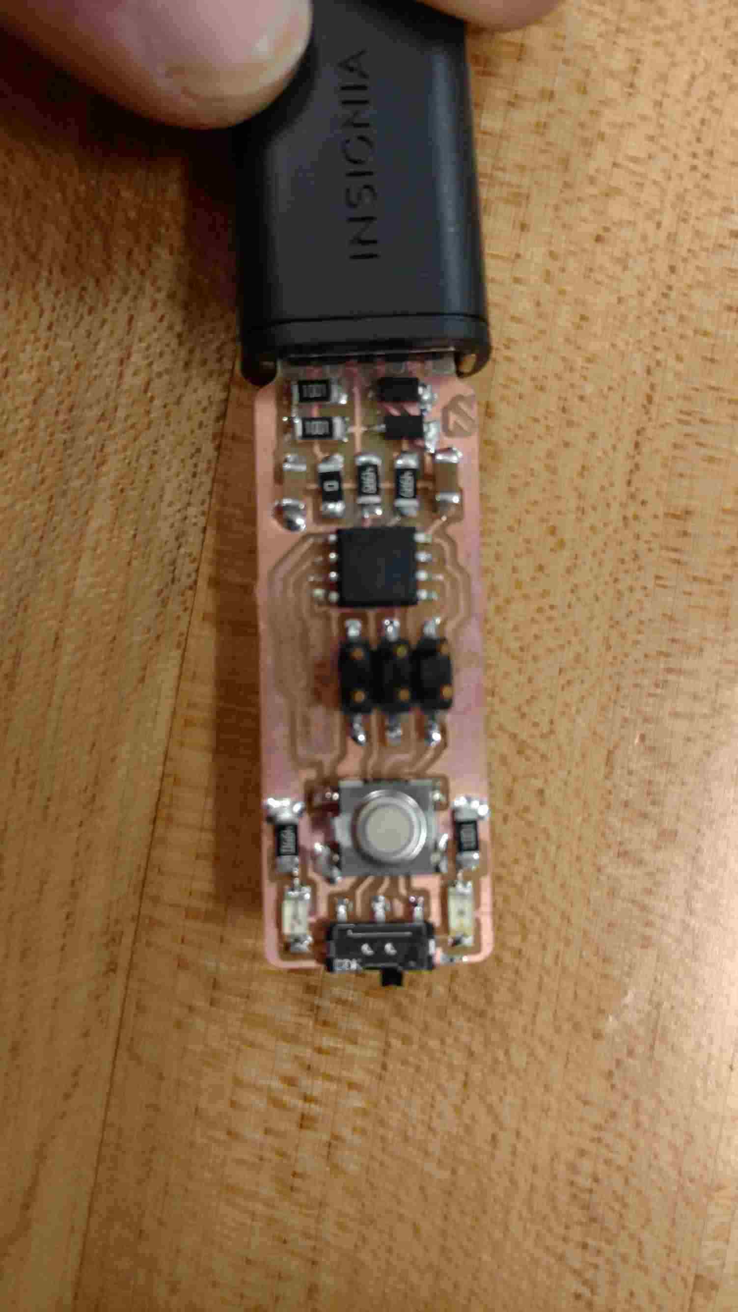
After the board it cut a quick check to verify the traces are all good you can then populate the board. Gathering all the components can take some time but after they are collected you can solder them down.
To program the ISP I followed the instructions on Zaerc website. I set up an Arduino and loaded the example ISP program and then followed the rest of the instructions on the page.
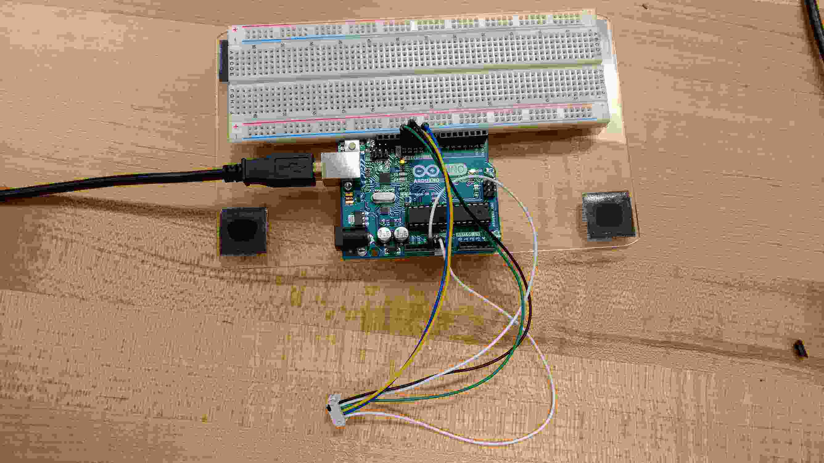
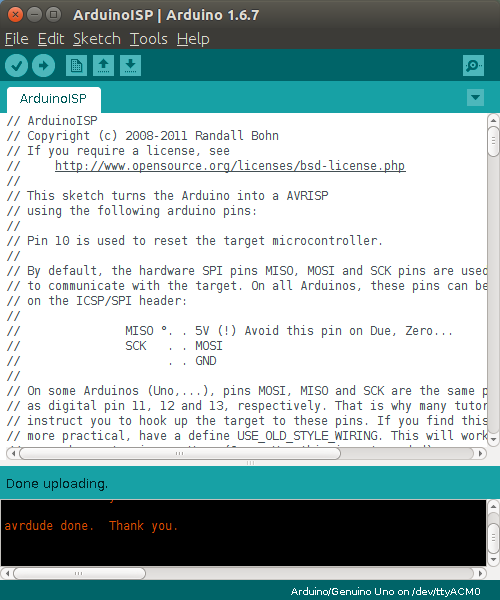
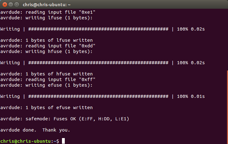
after hooking up the arduinio uno as a ISP and flashing the code it was time to burn teh fuses
Set or burn fueses
Avrdude -c stk500v1 -P/dev/ttyACM0 -b19200 -p t45 -V -U
lfuse:w:0xe1:m -U hfuse:w:0xdd:m -U efuse:w:0xff:m
program
you need to change two line in the usbconfig.h
//#define USB_CFG_DMINUS_BIT 4 comment out
#define USB_CFG_DMINUS_BIT 3
//#define USB_CFG_DPLUS_BIT 3 comment out
#define USB_CFG_DPLUS_BIT 4
you need to run the make command from the download of the
firemware
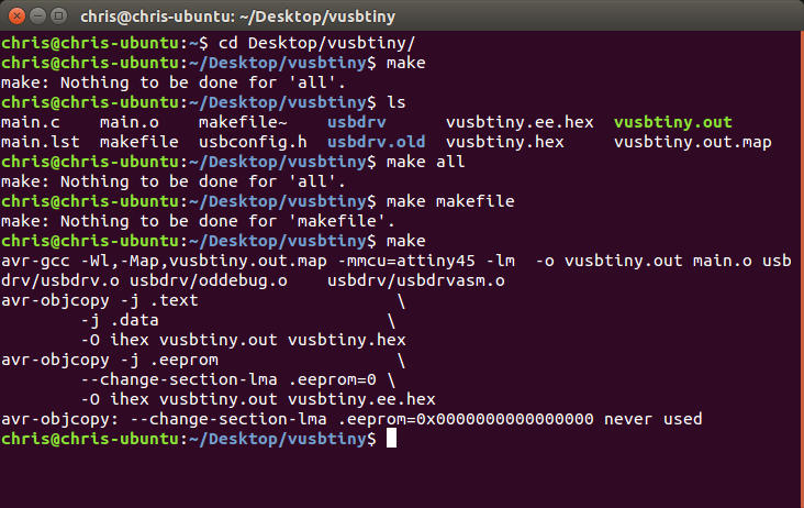
now its time to write the code to the attiny 45
in the make file you need to make sure you have the ritgh
programmer selescted in this case scine the arduino is being used as a ISP you
can use the fallowing
#AVRDUDE_PROGRAMMERID=usbtiny remove this
AVRDUDE_PROGRAMMERID=stk500v1 -P/dev/ttyACM0
-b19200 add this
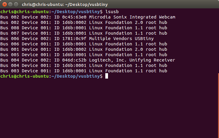
now all you have to do is type in make install
if it is all good when you plug in the your programmer and
use lsusb it should show up as multiple
vendors USBtiny
once you can see that its time to disable the reset-disable
fuse
avrdude -c tk500v1 -P/dev/ttyACM0 -b19200 -p t45 -V -U
lfuse:w:0xe1:m -U hfuse:w:0x5d:m -U efuse:w:0xff:m
after that its time to test.