Summary
This week’s
project was to create a parametric 2d design and cut it out on the
epilog
laser. For this
project I installed and
used a program called Antimony I have never
used this type of program
and have never really done too much CAD but I have programed before and
I found
this program easy to use for simple shapes.
The one thing I like about Antimony is that you can make a variable and
be able to change a size and have it propagate thru your design.
Press fit kit
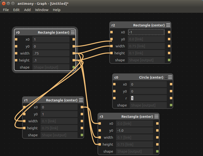
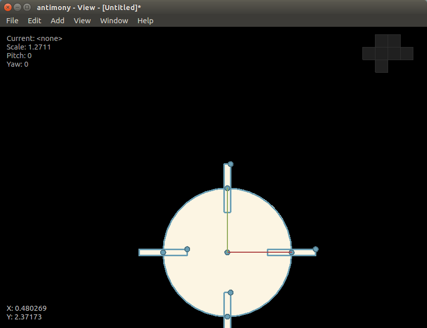
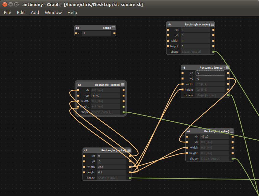
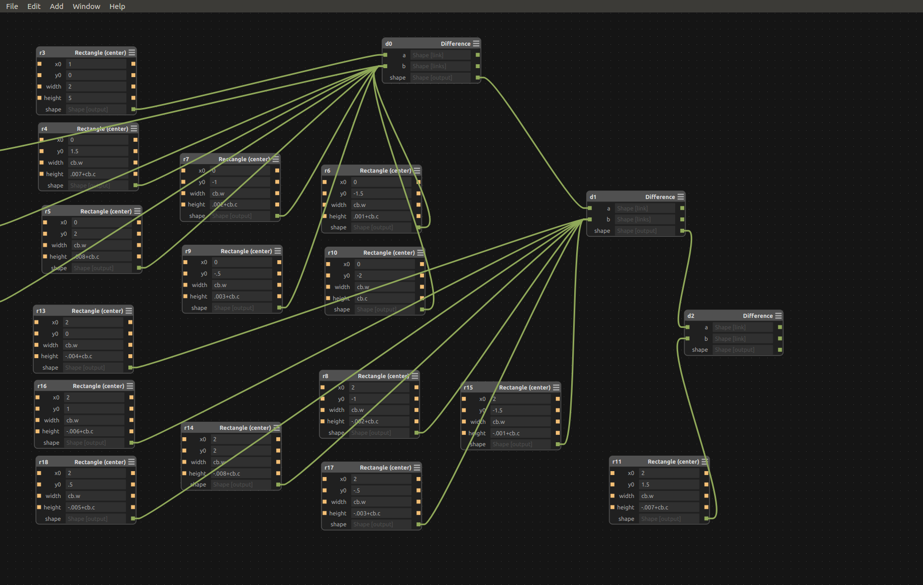
To start my press fit kit I had to learn Antimony so I created a simple circle and then added some rectangles to it. Each rectangle was cloned and the parameters tie together so if one changes they all change.
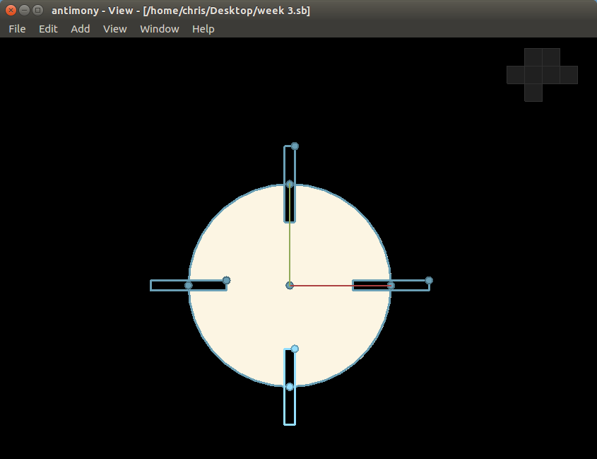
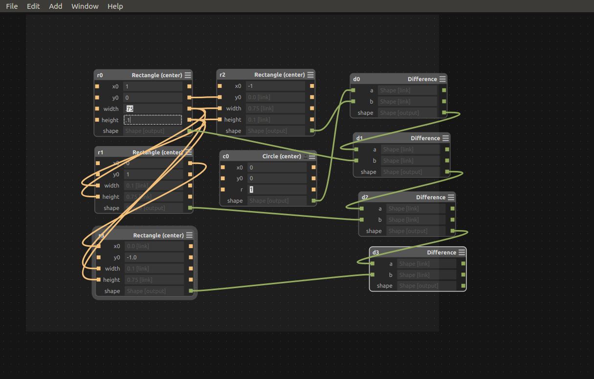
After figuring out how create the shapes I need to use the rectangles to cut slots so I needed to do a basic difference on the shapes at first I used 4 function later on when I created the square and the slot size test I only used one or two of them. I figured out that you can add more than one shape to the difference functions.
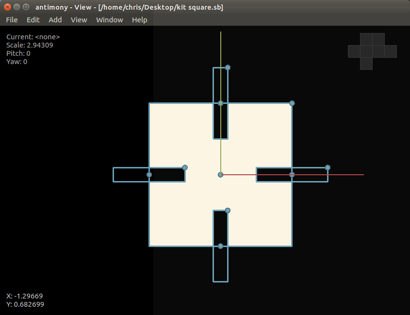
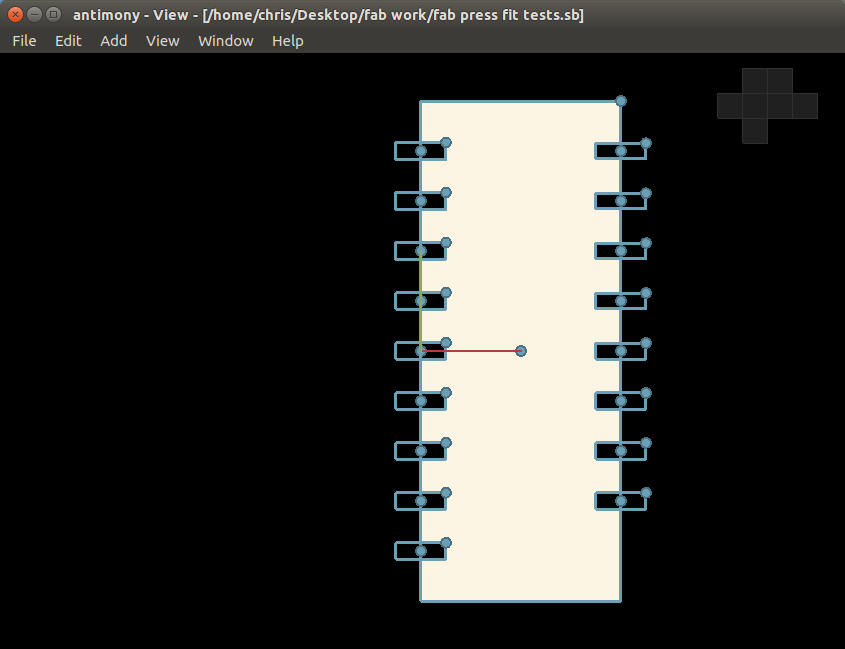
The next shape
I made was a square and did the same
techniques as with the circle but I wanted to use a variable to change
the
joint size. I
watched the class lecture
when Neil gave a demo on Antimony
and
found out that if you make a script
you can have a variable in it and use that for the shapes parameters.
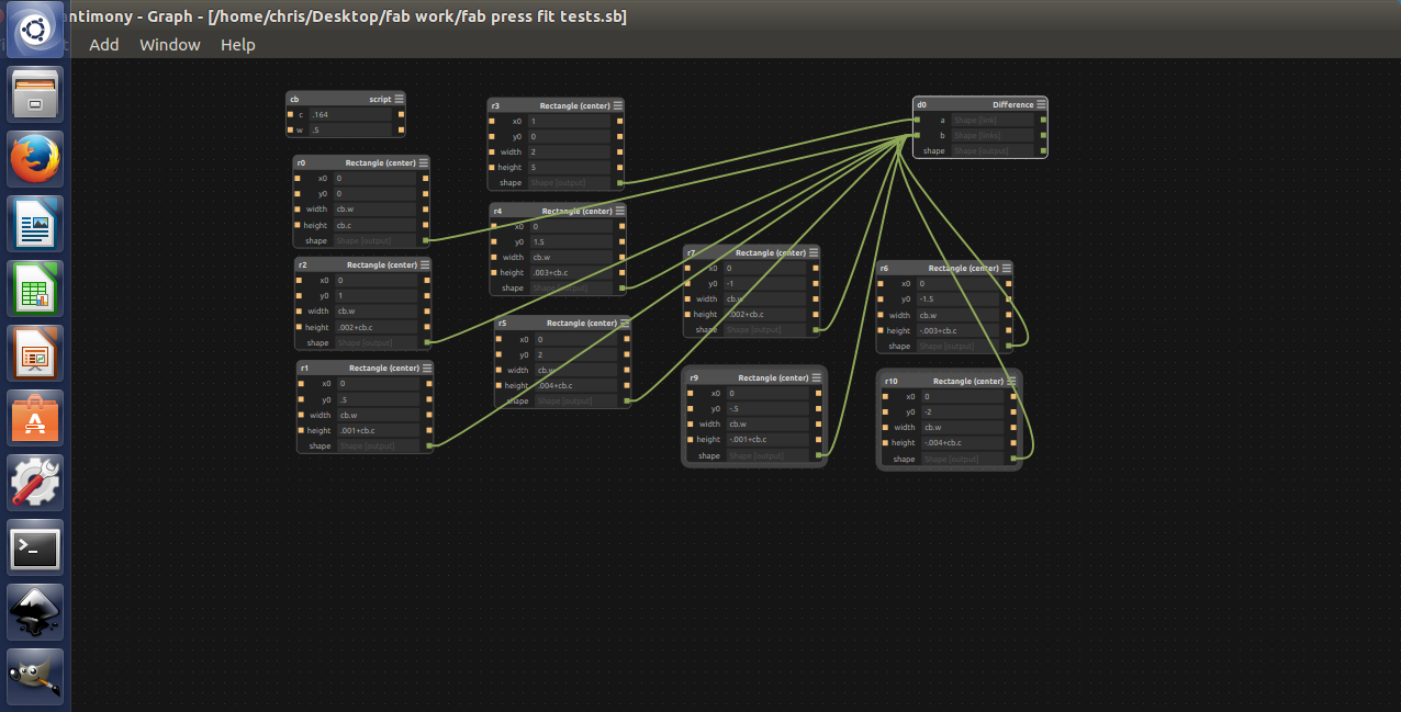
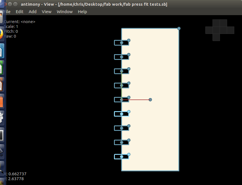
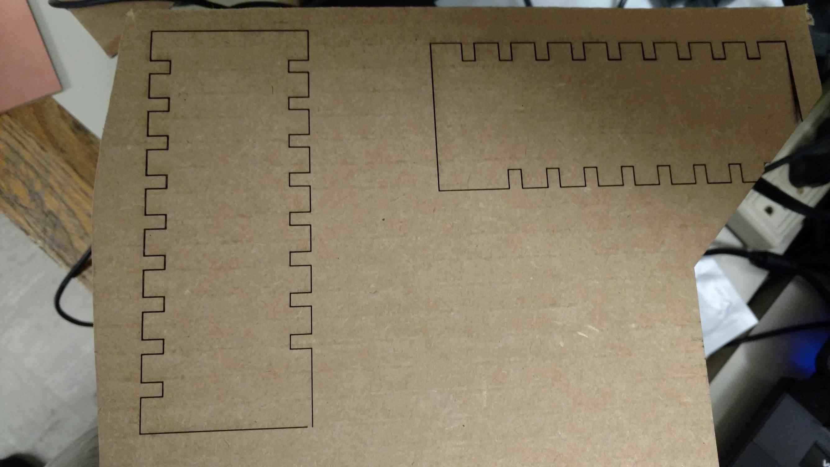
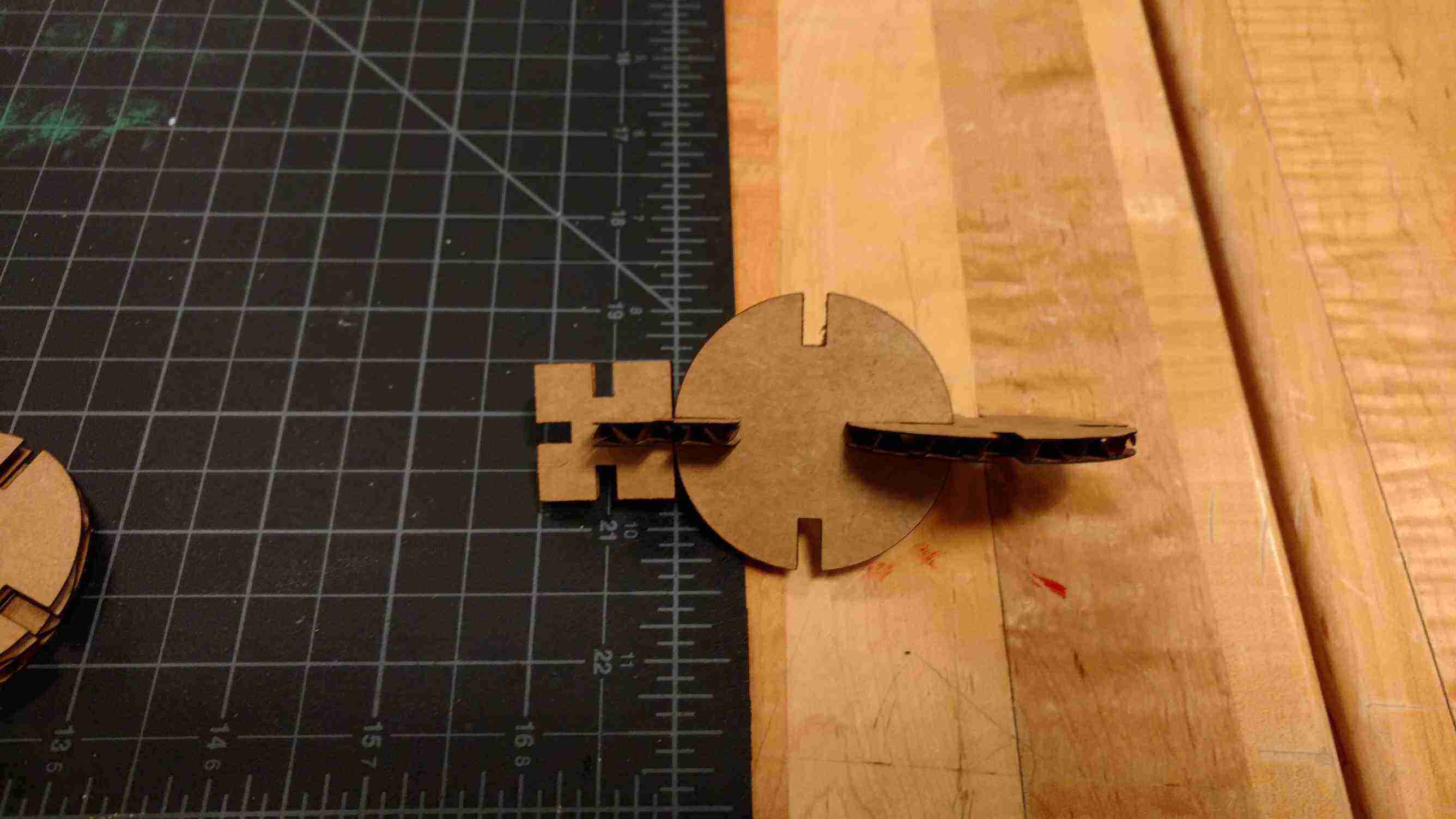
After I made a
few shapes I felt comfortable to design a
test file for finding out what size joint I would need to cut to create
a tight
fit on the cardboard. To
create my test
shape I copied the rectangles for the joints and in the size parameters
I used
variables and on each joint I added .001 of an inch up to .008 in .001
increments and also went down to -.008 in .001 inch increments of the
initial
size parameters.
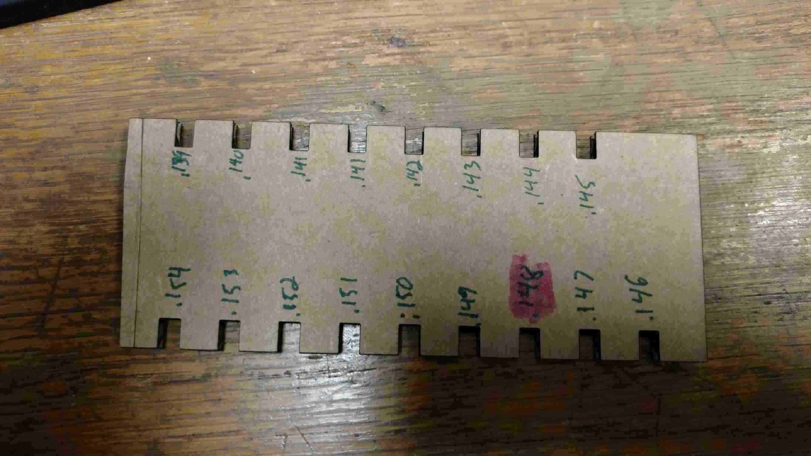
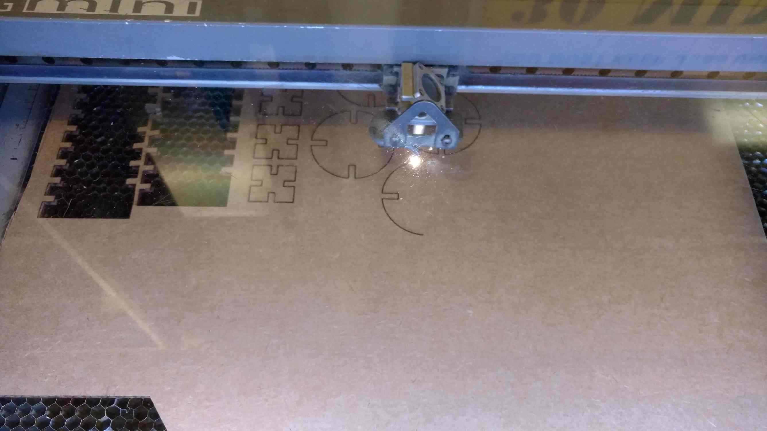
Epilog laser
To use the laser I had to convert the png from antimony to a svg using the fab modules. After I changed the files I imported them into CorelDRAW and I set the laser to the recommended setting of 100% power 26 speed and 5000 hz as a test to see if it will cut all the way thru. The first time it did not cut all the way so I had to slow it down. To finally get all the way thru I had to slow the laser down to a speed of 8 after that I cut two test prices for the joint with final coming up with a .148 inch. When I found the correct size for the joints I modified my shapes and cut a small batch to confirm the fit and it was good.
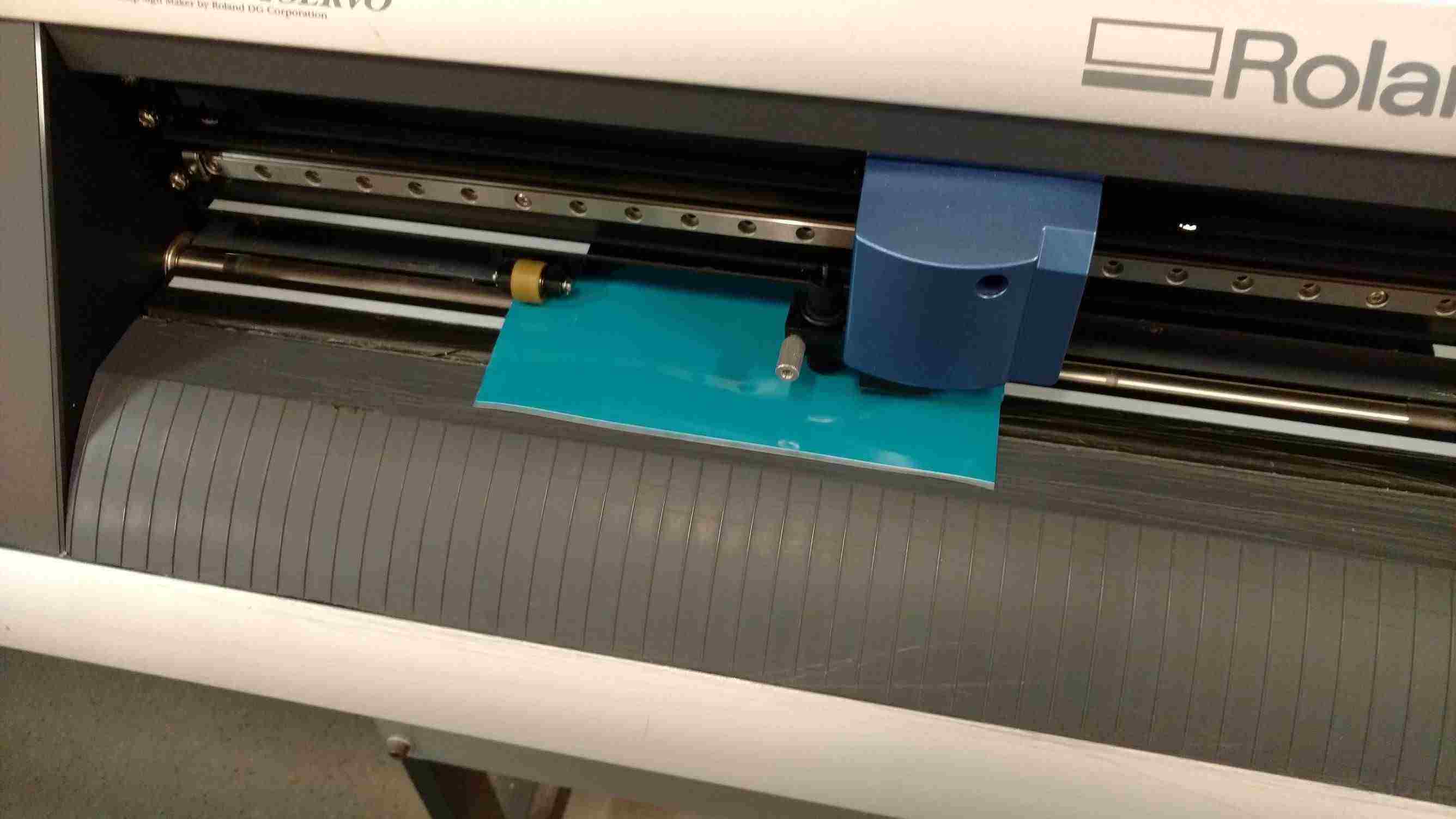
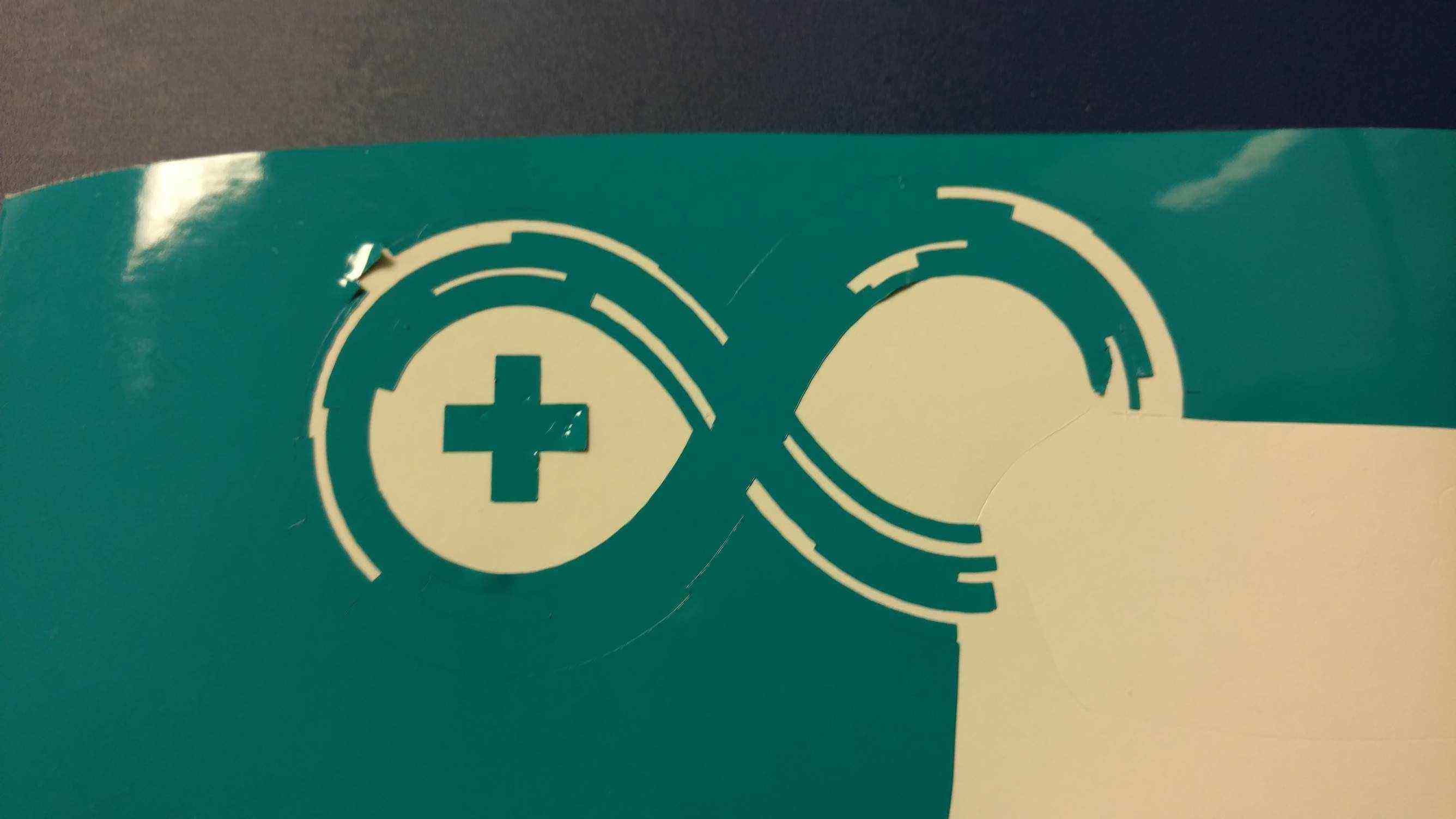
Vinyl Cutting
I have used the vinyl cutter once before but with help. This week I had some help setting it up from Kayleen she works in the fab lab as an assistant. For my design I used the Arduino open source community logo. It was very easy to have the vinyl cutter make the logo I used a piece of vinyl and the machine measured it automatically for me and the size was imported into the cut studio where I was able to make multiple copies. The longest and hardest part was the weeding of all the non-essential pieces.

Files