This week our task was to create a circuit with a microcontroller
on it that takes an input. I decided to
use a Hall Effect sensor this sensor measures a magnetic field.
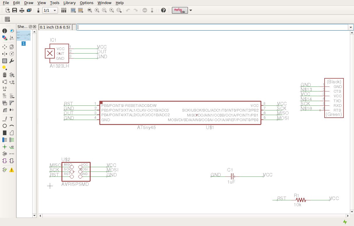
To create the board I based my design off of Neil’s on the website. I used eagle to draw the schematic and it transferred it to the board layout side to lay out the board. I used a ground plane to help with routing.
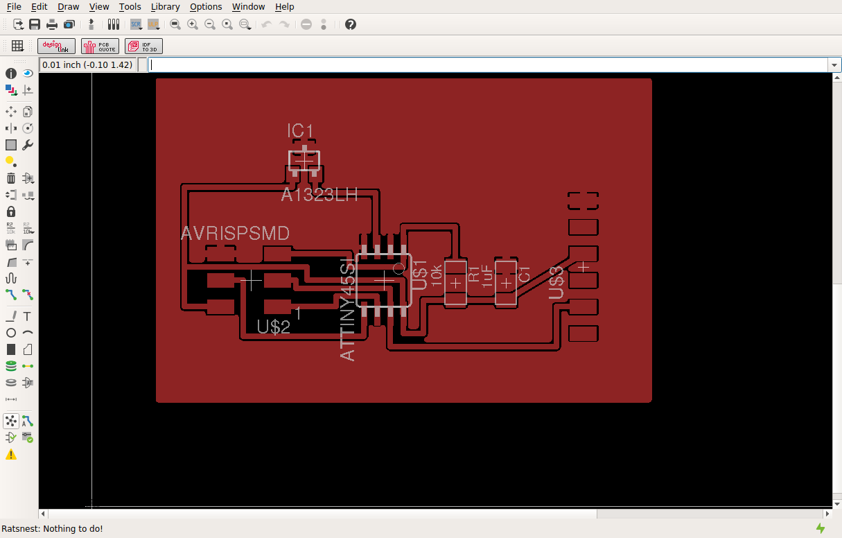
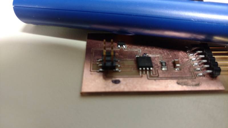
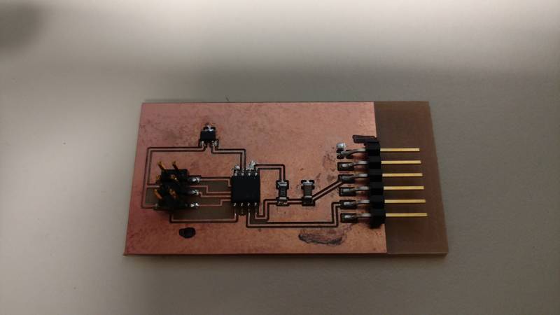
The next step was to cut the board out and then populate it. To do this I had to use eagle to export a Gerber
file so my LPFK could cut the board. The
hardest part was looking through the box of parts to find the right components.
To program I used Neil’s code and the python file to see if
it was working. After that I went into understanding
some of the code.
The first part of the main function is setting up the Analog to Digital Converter.
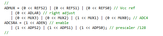
We shift a one into MUX1 to enable ADC2 on PB4 and also set
the voltage reference to VCC by setting REF2:0 to all zeros.
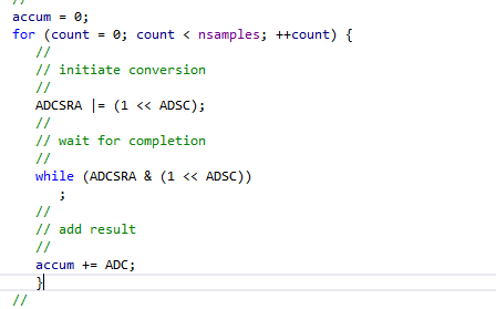
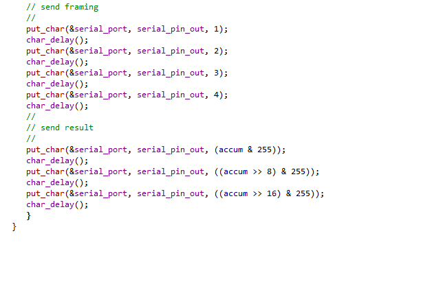
The next part is to take a 100 reading and store the values
and then breaks up the data to send it over the serial interface to the python
script.
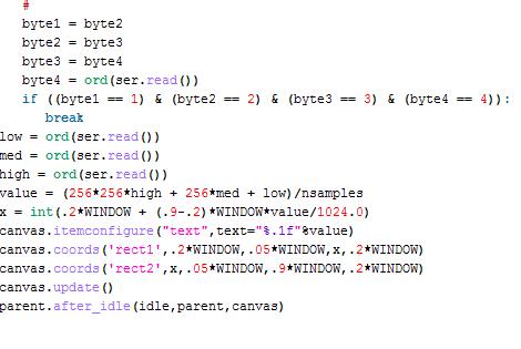
The last part is the python program. This program take the serial data rebuild the ADC accumulated value and then take the average.
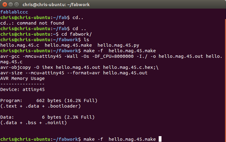
To compile the code the make file was used with the
following syntax
Make –f hello.mag.45.make
This compiled the code in to a hex file for flashing.
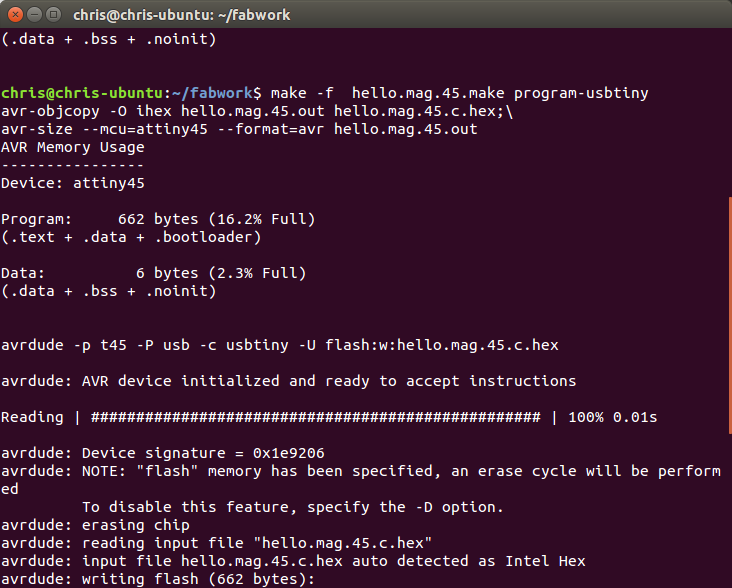
The next step was to flash the code to the micro.
Make –f hello.mag.45.make program-usbtiny
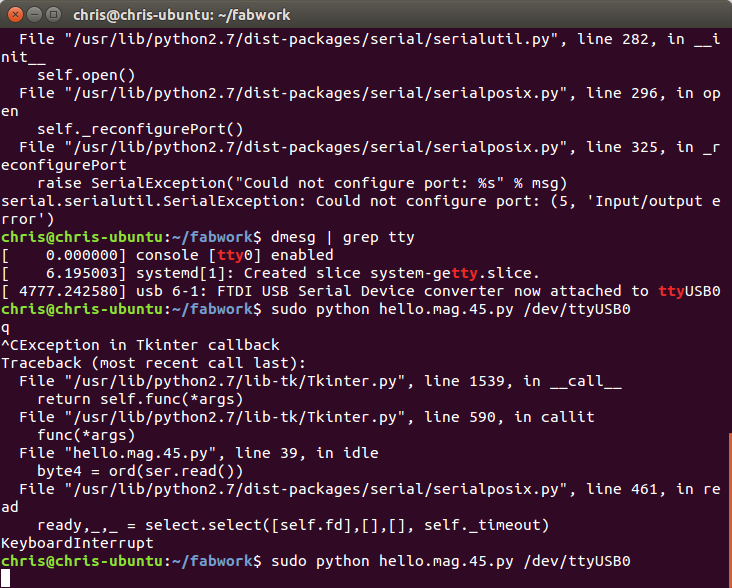
The last part was to run the python code. The only hard thing I had with this was how
to run it. It was asking for a serial
port and I had to find out where the FTDI cable was installed to.
I found this out by using dmesg | grep tty I found out that it was on /dev/ttyUSB0 after adding that to the end of the python
the code ran fine.
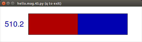
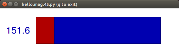
The below are screen captures of the value changing when a magnet is placed by the sensor.