
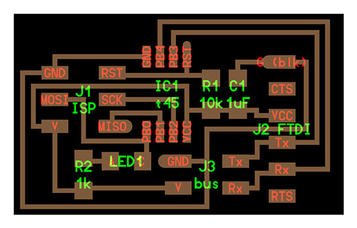
In this week we need to build a network out of 2 or more processors, and in this week I'll use Neils board. I downloaded trace and interior png file from the fabacademy's page. After that, I use the fabmodules to make RML file, then I made one of hello.bus.45.bridge and two of hello.bus.45.nodes. I also use Roland SRM-20 to make the board and this process is documented on week4.
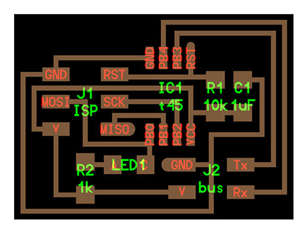
node
bridge
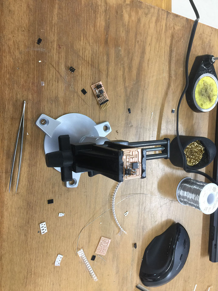
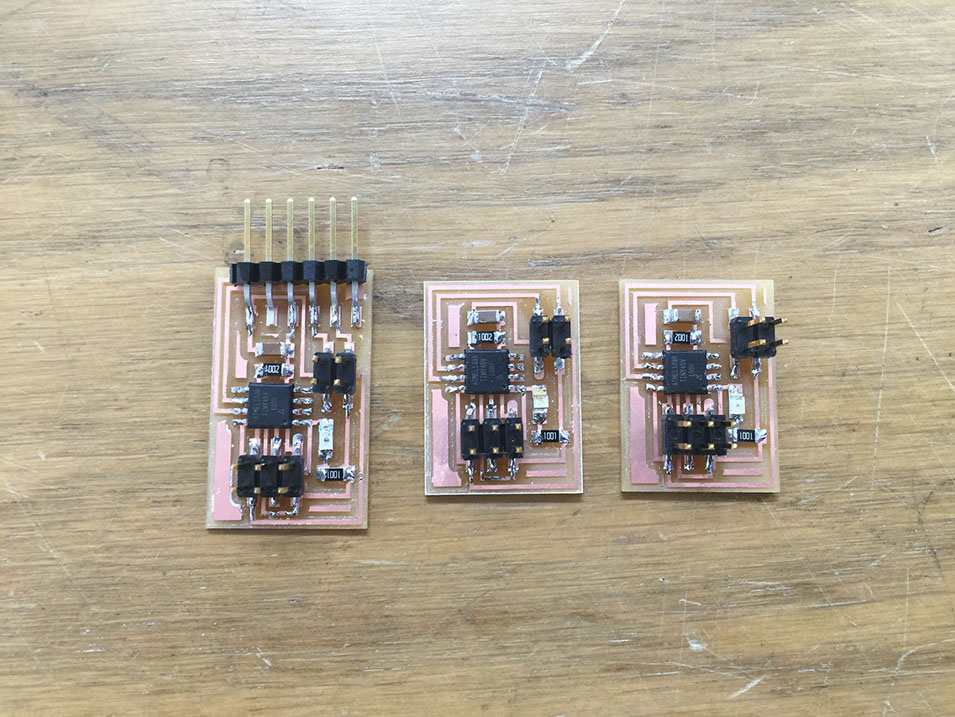
When I connect the board to the computer, the board be smoking ........I checked the circuit board again and again. Finally I found the ATtiny 45 are all welded as the wrong direction as above.......Then I took them all off and welded again.
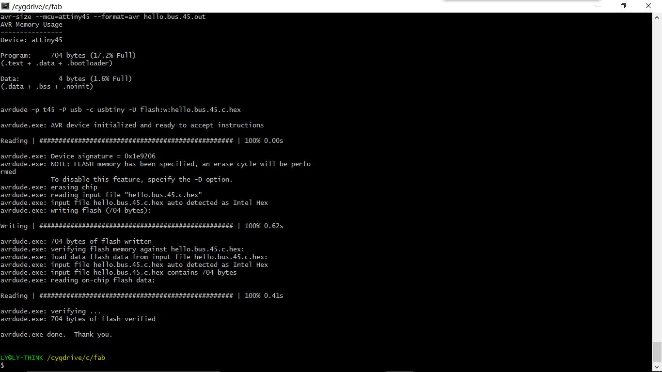

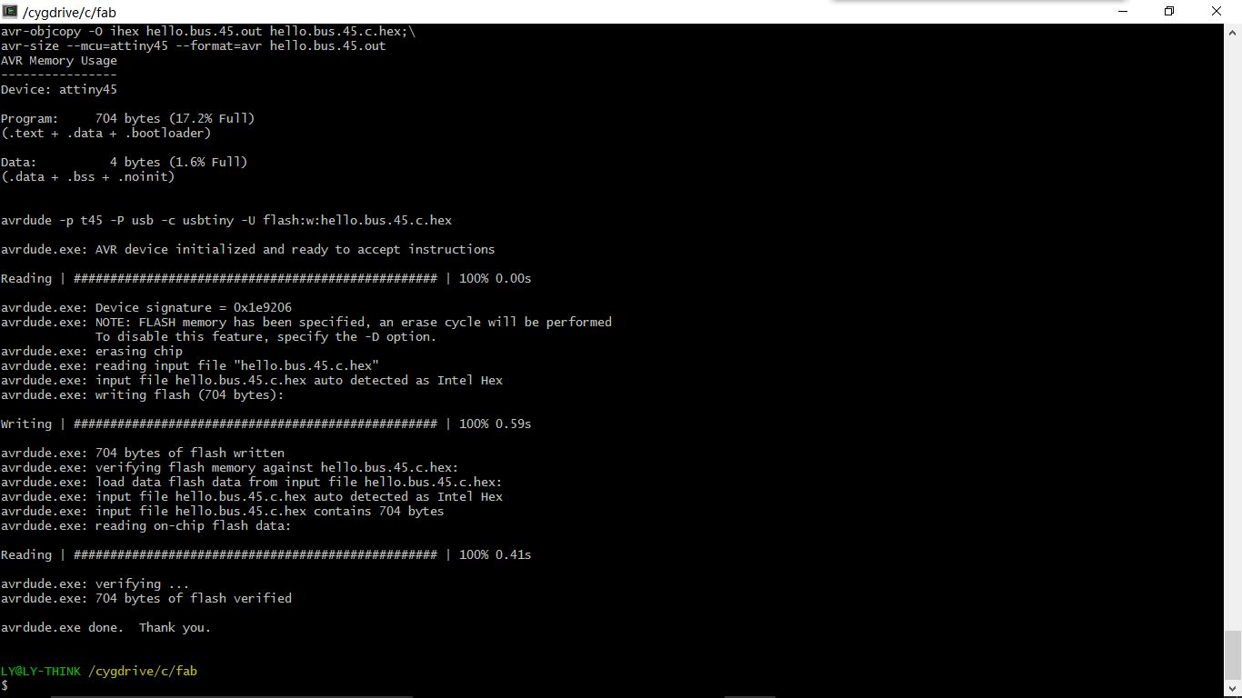
First, I downloaded the C file and Make file from fabacademy's page. Then I connected the FabISP to board with 2x3 wire one by one.
The default node_id is defined as 0 with following C code.( #define node_id '0' )
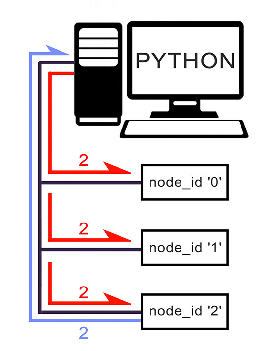
There is 3 board in my net work system, and i need to give each board its own id.
so i set:
Bridge board: #define node_id '0'
Node board 1: #define node_id '1'
Node board 2: #define node_id '2'
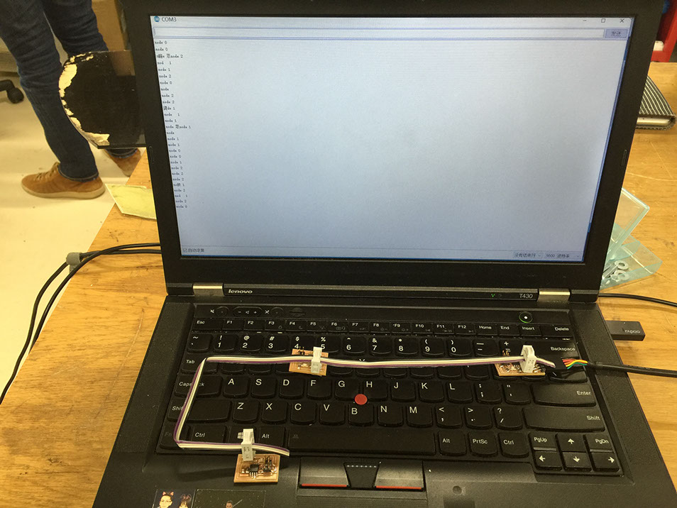
By "if(chr == node_id){}" the board will compare the serial data with their own ID.
As a result, if I type "0" from computer, the bridge board's LED will brinks 2 times, if I type "1" ,the node board 1 will blinks 2 times and when I type "2", the node board 2 will blinks 2 times.
So a network with 3 processors has been completed.
Serial communication is like above: python application send 2 to each nodes and only node_id2 respond 2 to the computer.