LESSON TEME: Electronics Design
In this week, I tried to make FabISP. At first, I added my own sketching image to a png file designed an electronic board which is already designed by Neil. Then, I upload the png file to fabmodules.org and export a rml file after setting several parameters for a Milling Machine. A milling machine in Fablab Kyushu cut out the designed board from a PCB. I soldered several electronic devices on the board and wrote a firmware code for FabISP on the board.

Designing Electronic Board
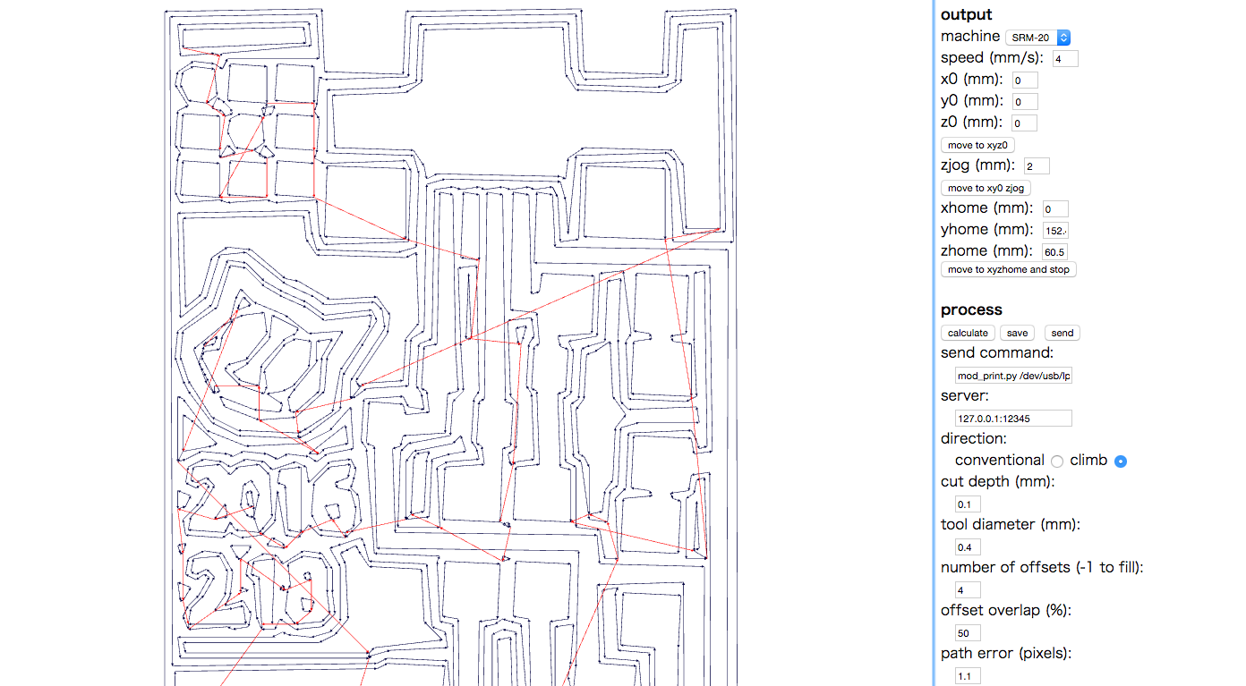
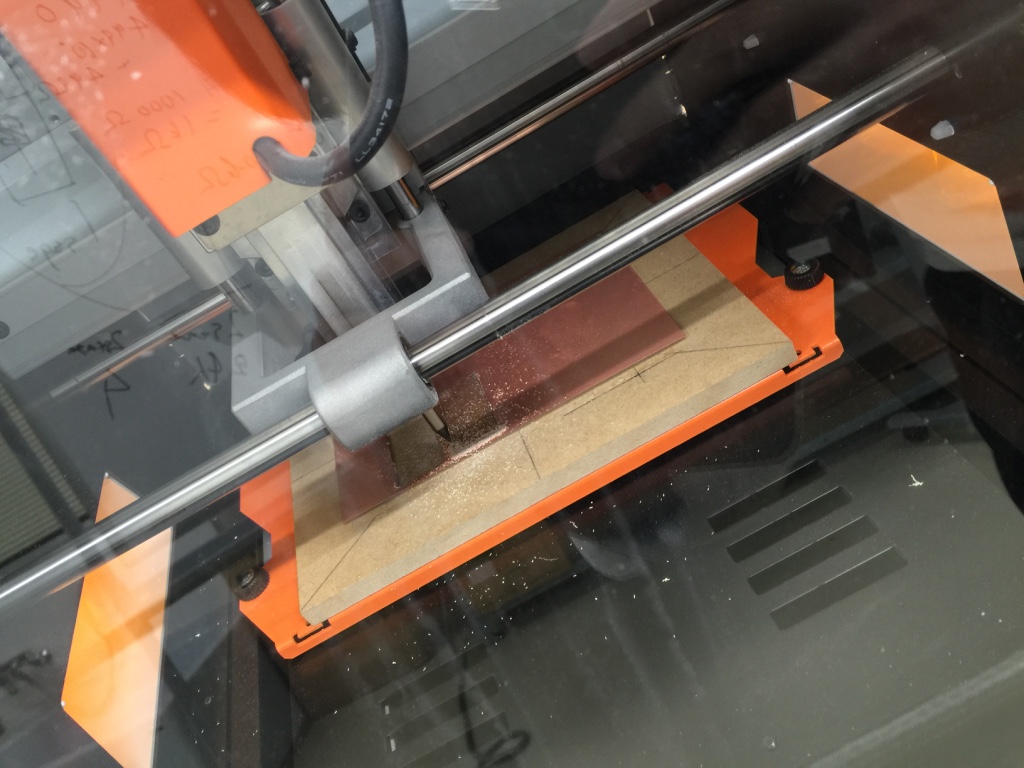
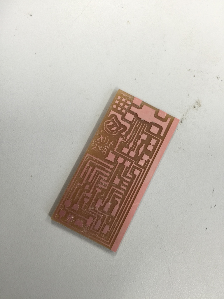
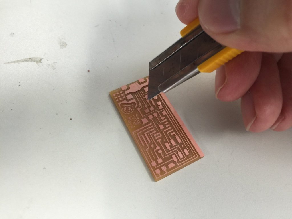
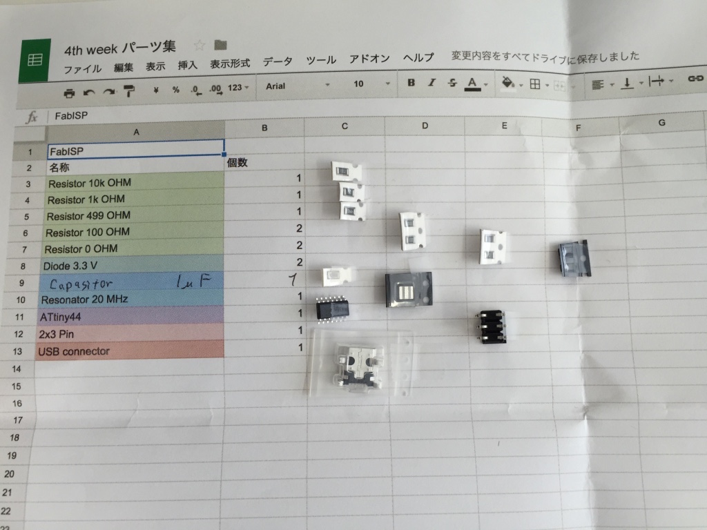
I added my own image, a cat character and date of today, to a png image of a electronic board. I can select several types of boards, which are already prepared, finally I selected Neil’s FabISP board. I uploaded two png image file to fabmodules.org. One is TRACES image describing an innter designed of the board. The other is INTERIOR image describing an outline shape cutting out the board. Both images need to be only two color; black and white. Black areas are millinged out, otherwise white are remaing on the board. Befor exporting the rml file, which is a milling data file, I have to set serveral parameters for milling the design from PBC. For example, diameter size of the endmill for the TRACES file is 0.4 mm and the INTERIOR is 0.8mm. Then, I send the rml file data to a milling machine. I had to take care to handle an endmill because the tip of it is too thin. Finally, the designed board was cut out. It took about 20 min to cut out. Several remaing parts are removed out by a cutter.

Solder Electronic Parts
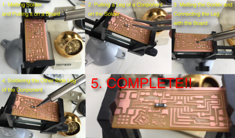
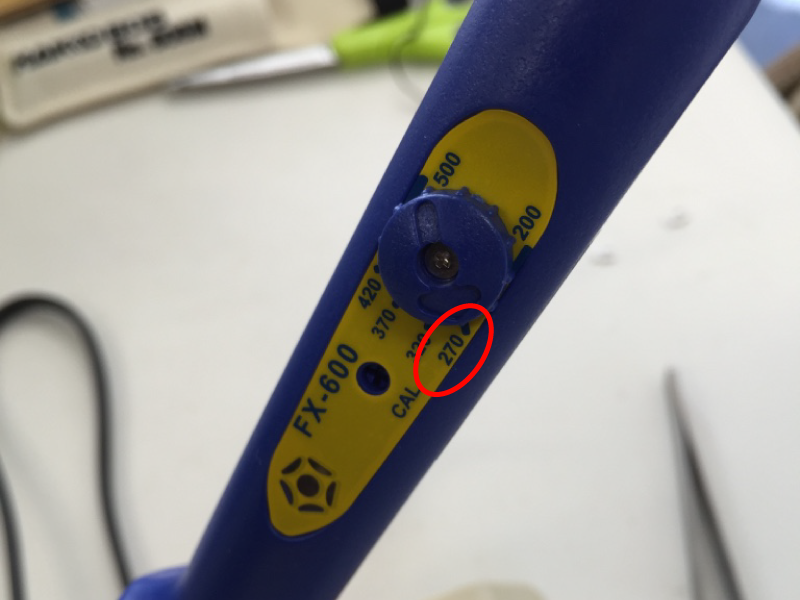
I soldered several surfece mount components on the board. This is my first time to solder them, though I have experience to solder more large parts. The components are too small so it's better to prepare a tweezers to pick up them and a vise to settle a electric board. The soldering works are bit different to usual soldering works. At first, melting solder and put it on a place where connecting a leg of componets. Puting a leg of the componet on the solder. Melting again the solder and connect the leg of the component. After checking the connecting situation whether the componet are enough fixed or not, then lastly, soldering the other leg of the component. In a case of a componet with many legs, it need to solder the legs by diagonally acrossing order. The heat temperature seems to be 270 ~ 300 degree Celsius, it's my heuristic paramter though. A desolder sheet was also useful because these bus widhts of componets and the electric circuits are so narrow. For effective solding works for a surface mount, these componets should be soldered from centered ones to outside ones. Finally, I made a FabISP board. I also checked the conditions of electric current by a tester.


Write Firmware on Board
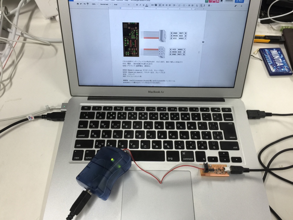
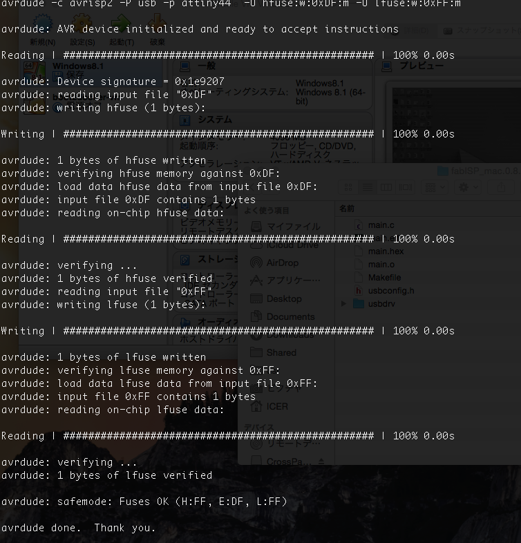
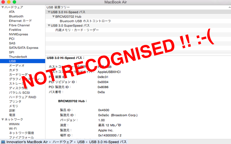
I write a firmeware code to the board by using an AVR writing machine. Connecting the AVR writing machine to Macbook Air and also connect the FabISP to Macbook Air and finally, connecting the AVR with the FabISP; like a circuit by devices and cables are made. Then, I executed several "make" commands to write a firmware code on the board. But my Mackbook Air can't recognise the board, come on! :-( I have no idea why the board can't be recognized.
Impression
It's my first time for using a milling machine and soldering a surface mount componet. I found that an endmill are too thin so I have to take care to handle it. For soldering works for a surface mount components, a tweezers and vise are so helpful. These componets are too small so the sheet pasting a componet acoording to the componet name is helpful for the mounting works. As a soldering tips, when melting solder after puting a leg of coponet, it may be better to pick up a componet by a tweezer by left hand and melt the solder by the right hand and then, begining to melting the solder, quickly INSERTing the componet by a SIDE of the melting solder. The soldering works is more successful for me than puting a leg of a componet on melting solder.