FINAL PRODUCT: DIY Electric Skateboard
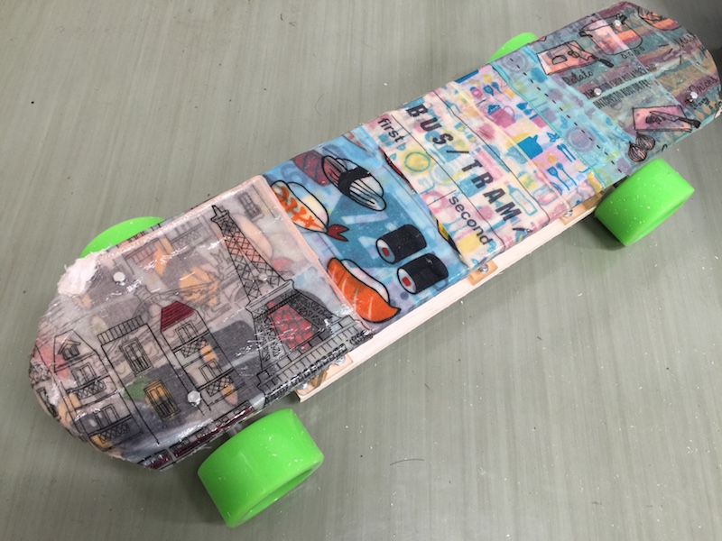
My Final Project is DIY electric skateboard. The skateboard can be controlled from a laptop computer via bluetooth wireless commnication. Figure [1] shows the actually product. The surface board was cutouted by using Shopbot. The board is enclosing by cotton clothes with expoxy resin in order to harden the board. The undercase contains electronic parts is made by wooden boards and several joint parts made by 3D printer. The main board to control the skateboard is connecting a bluetooth module receving signals from the laptop computer. The software application sending signals from the computer is implemented by Python.
Plan and Architecture
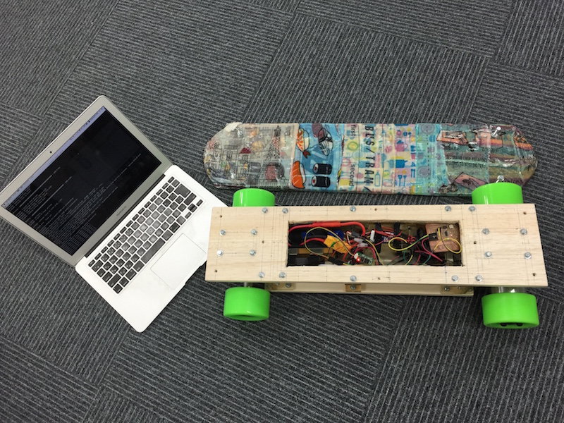
Figure [2] shows an image for my DIY electronic skateboard.
The user has a mobile device to control the skateboard.
The mobile divece sends a signal for moving the skateboard forward.
The bluetooth module, in undercase below the main board, receives the signal
and sends signal to rotate the hub motor via electronic speed controller (ESC).
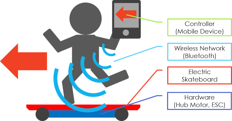
Figure [3] shows the electronic architecture of the skateboard.
The figure also shows INPUT/OUTPUT functions.
The INPUT is the signal from the laptop computer by uisng serial communication.
The OUTPUT is to rotate the hub motor.
The architecture uses two power battery; one is for the electronic board, the other is for the hub motor.
The electronic board uses a normal battery which has 5V.
The hub motor uses a lithium polymer battery which has 6 cells, 3,000mha and 20C.
For a safty, there is a Anti-Spark plug between the battery and ESC.
I don't use the Battery Eliminator Circuit (BEC) in this time.
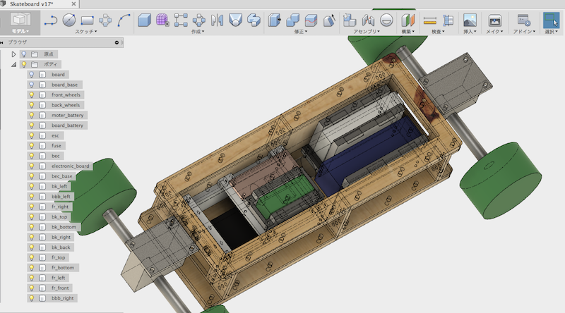
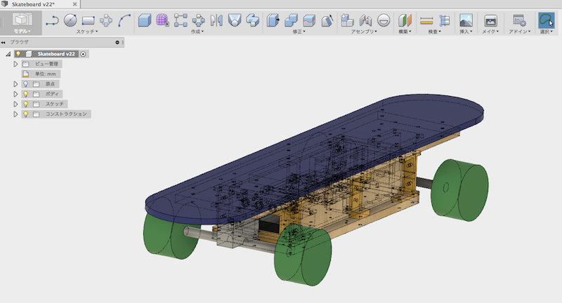
CAD Design Works
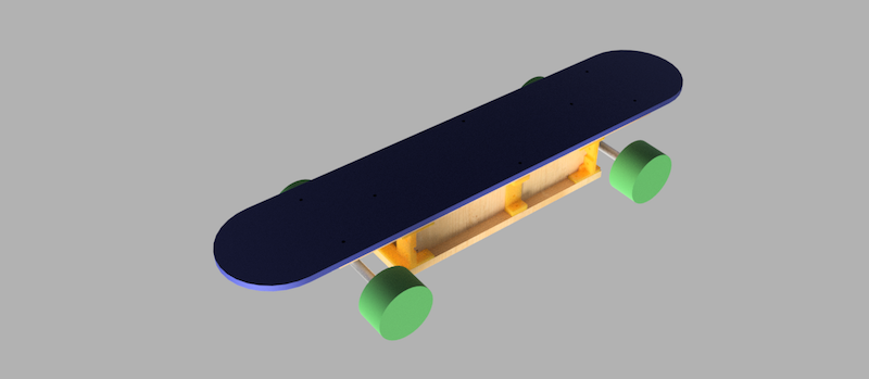
Figure [4] shows the CAD design of my electric skateboard. These inner parts to fix the battery and electronic components are also made 3D printer. The ESC is in the bottom of the case. The black object in the figure [4] is the ESC. The ESC is covered by a box made by 3D printer. The electronic board and BEC are settled on the box, which expressed the green and gold object in the figure [4]. The two batteries are settled on the rear side. The blue and white object in the figure [4] express the two battery. Several joint parts outside of the case are also made by 3D printer based on the design [5]. Figure [6] shows the rendering image of the skateboard.
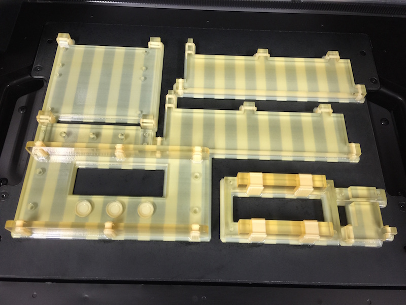
Building Works
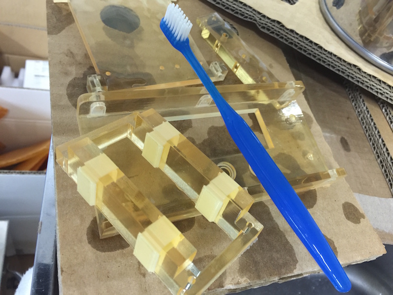
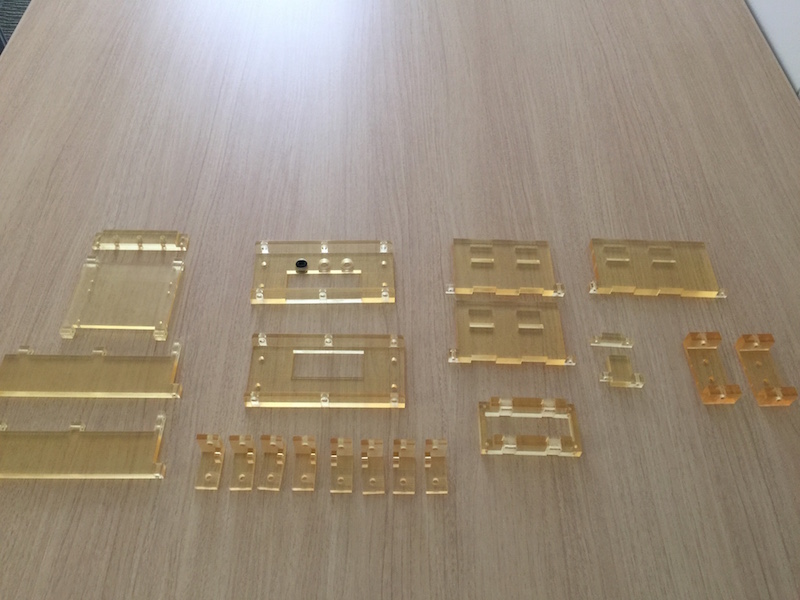
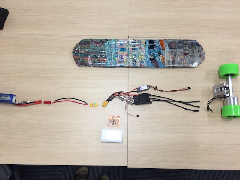
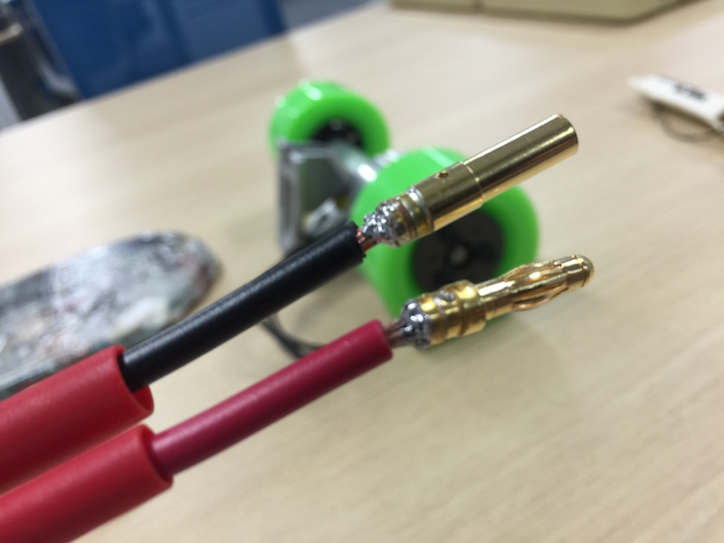
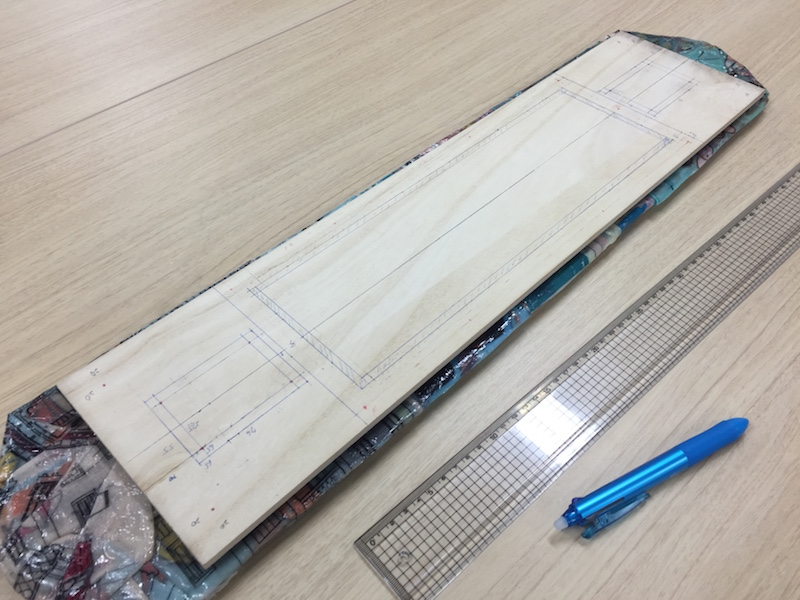
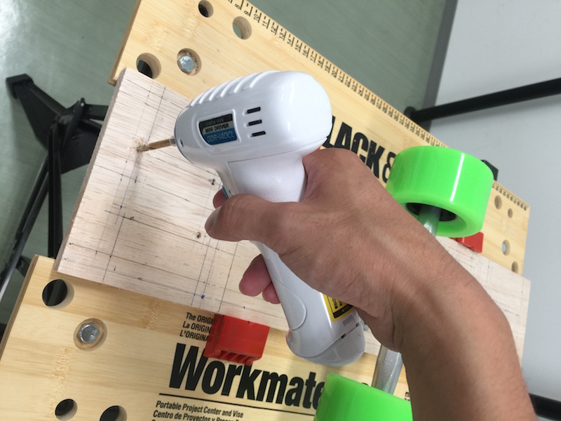
Figure [7] shows several printouted innter parts of the skateboard. The resin parts still with supporting materials, so I removed them by using a brush [8]. The final product of the all innter parts is shown in Figure [9]. The left side parts are to fix the ESC, BEC and electronic board. The second ones from the left side are outside parts; the front/rear parts and joint to connect wooden boards. The right side are innter parts to settle the two batteries. Figure [10] shows outline to connect each electronic components. The right one is the hub motor. The center ones are the ESC and electronic board. The white case is a battery for the electronic board. The blue one in the left side is the lithium polymer battery for the hub motor. I connect each part by using soldering works [11] and fixed them by using heat shrinking tubes [12]. Then, I mede the undercase containing the electronic parts [13][14]. The main work in this process is to make a hole according to the CAD design. I built up all parts for the skateboard [15] and lastly set the electronic board on the skateboard [16]. I finally made the DIY electric skateboard [17]. Currntly, the skateboard doesin't work well. The laptop computer and electronic board can communicate each other but the hub motor is no response. Probably, the ESC is broken and I'm importing another ESC. I'm surprised that I can ride on the skateboard. It's harden enough to ride 60kg object.
Electronic and Software Works
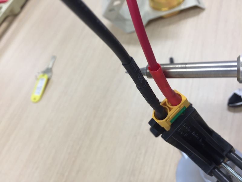
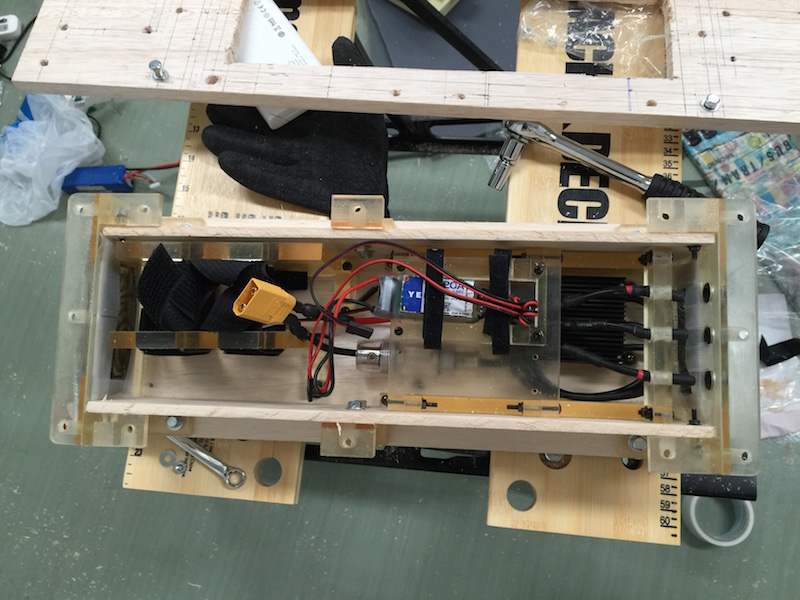
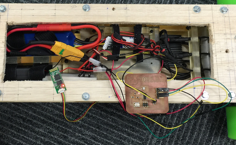
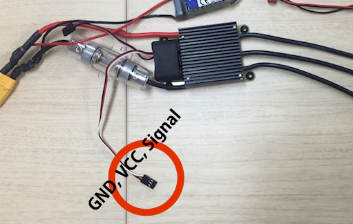
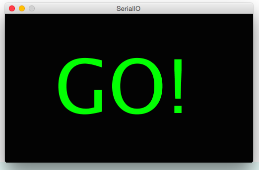
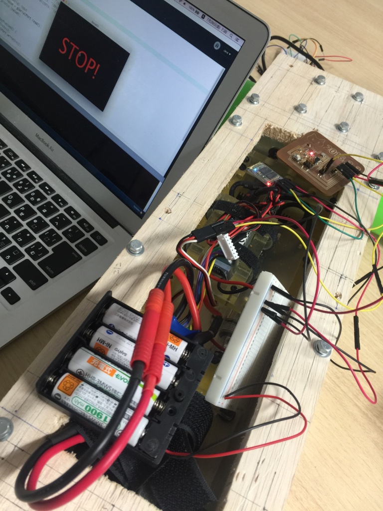
Figure [16] shows the inner electronic parts. The main board is connected with the bluetooth module and the ESC. The board is seprised power from a generic battery (5V). The board waiting to listen a message from the laptop PC via Bluetooth serial communication. Figure [17] shows a part of the code to listen the message. If the message is the same code of "go_signal", the board send a signal to the ESC to rotate the hub motor. The ESC has three cables to control the motor [18]. The configration is very similar to the servo motor. One is VCC pin, second one is GND pin and the last one is the Signal pin to rotate the motor. Figure [17] also shows the code to rotate the motor. The "go_signal" is sent by a controller software running on my laptop PC. The software is implemented by using Processing. Figure [19] is the interface of the software. The oparation is very simple that if I want to move, I only keep pressing the "1" key. If I want to stop, the release the key and push another key. Figure [20] shows apparance of testing the serial communication between the main board and the software.

Final Appearance
Figure [20] shows the final apparance of My DIY Electronic Skateboard! The Lisence is CC-BY (Creative Commons Lisence 4.0). I learned about the ditals of the motor and ESC and also AVR programming for wireless network communication. As questions still need to be resolved, how to effectively rotate the motor, sometimes the rotation system doesn't work well. I have to write the more effective codes to rotate them. And I have to repair the ESC which was brokened in my experimantal development.