08. Embedded Programming
Assignment
Read a microcontroller data sheet
Program your board to do something, with as many different programming languages and programming environments as possible
Lecture
Making my Hello Board
First I finished my Hello board making which was the week6 assignment.
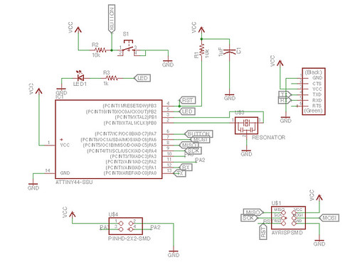
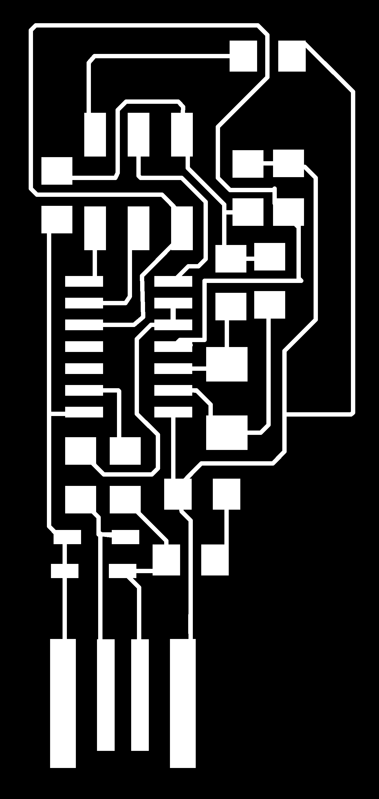
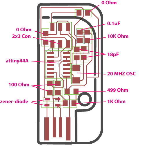
Board Design
I put one LED and one button on my board.
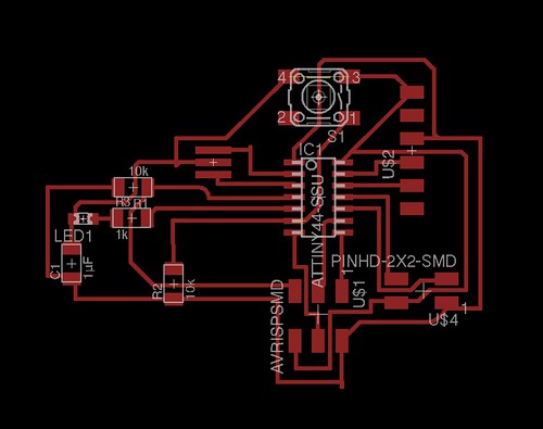
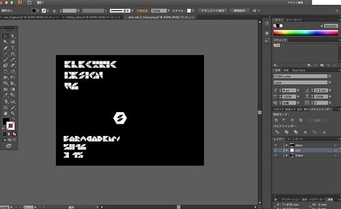
I added words of date for decoration with Photoshop. So I made 3 png files: 1) trace 2) words and decoration 3) cutout.
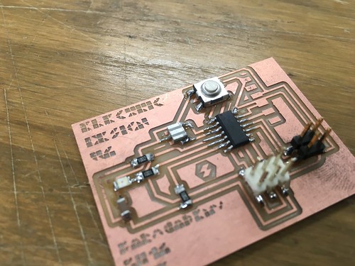
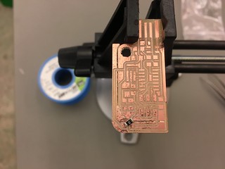
Done the milling PCB board and most of parts:
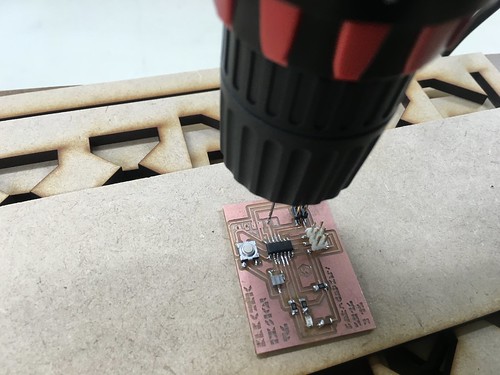
Making holes for FTDI pin
The FTDI pin we have need holes to be fixed on the board but I didn't make any holes on Eagle. So I made holes manually with 0.1mm drill.
Then, soldering the FTDI pins to the board.
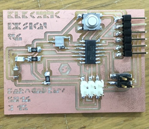
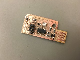
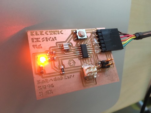
Hello Board
This is the outcome of Hello Board making.
ISP layout
Download the Hello Board files
Trouble:breaking FabISP
I was trying to send program with FabISP and accidentally I broke my FabISP's 2x3 pin part when I put it on my laptop and I closed the top of laptop.
It was sad.
Learning: Fix the parts with Glue Gun before breaking it.
Here how I broke my FabISP:
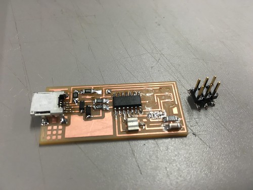
Making a New FabISP
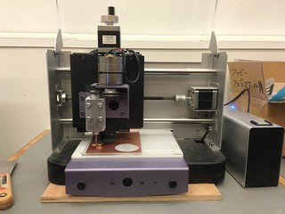
For new FabISP I change the model to Valentin's FabISP. I used CNC machine “kit mill CIP100” and saw the documentation by Miki Nakazawa.
I removed the all parts from the broken board and transplanted to new board. I didn't need to program the FabISP again since the ATtiny44 have been installed the program before.
board layout of valentin's FabISP
Microcontroller Datasheet
ATtiny44 datasheet
I didn't have any experiences about ATtiny microcontroller. I have done some project with Arduino, but Arduino gently kept me away from the deep microcontroller world.
I chooseATMEL ATtiny24 ATtiny44 ATtiny84 datasheet since ATtiny44 is major microcontroller in FabAcademy.
First, I was surprised how much information the datashee has in 286 pages. It's not like tutorial but more like a dictonary.
I felt that the microcontroller is a translator of Analog and Digital / atoms and bits.
Learning notes are following:
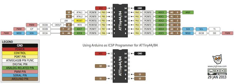
◯ Pinout of ATtiny24A/44A/84A in page2 is very useful to identify which pins have what functions.
◯ The pins named "PAx" = PortA is a 8-bit bi-directional I/O port with internal pull-up resistors.
◯ The pins named "PBx" = PortB is a 4-bit bi-directional I/O port with internal pull-up resistors. PB3 has RESET function.
◯ ATtiny44V-10 series work with 10MHz / ATtiny44-20 series work with 20MHz.
◯ ATtiny44 contains 4K(=4000) byte On-chip In-System Reprogrammable Flash memory for program storage.(ATtiny24 has 2K byte one, ATtiny84 has 8K byte one.)
◯ The ATtiny44 contains 256 bytes of data EEPROM memory.
◯ The ATtiny44 contains 256 bytes of SRAM. It has 32 Registers and 64 I/O Registers and 256 byte Internal SRAM.
◯ Clock: Calibrated Internal 8 MHz Oscillator(CKSEL to "0010") / Internal 128 kHz Oscillator(CKSEL to “0100”) / External clock(CKSEL to "0000")
The pinout of ATtiny 44 is useful for designing board. This image by http://www.pighixxx.com/ is good for me because it shows various functions that ATtiny pins have and Arduino pin compatibility.
Embeded Programming : C language
Blinking LED on Hello board
First, I programed the code that make LED blinks.
            #include <avr/io.h>
            #include <util/delay.h>
            #include <avr/pgmspace.h>

            #define output(directions,pin) (directions |= pin) // set port direction for output
            #define set(port,pin) (port |= pin) // set port pin
            #define clear(port,pin) (port &= (~pin)) // clear port pin
            #define pin_test(pins,pin) (pins & pin) // test for port pin
            #define bit_test(byte,bit) (byte & (1 << bit)) // test for bit set
            #define position_delay() _delay_ms(1000)

            #define LED_port PORTB // Port B Output Resistor
            #define LED_direction DDRB // DDRB 1:Output 0:Input
            #define LED_pin (1 << PB2) // use PB2 pin


            int main(void){

               CLKPR = (1 << CLKPCE);
               CLKPR = (0 << CLKPS3) | (0 << CLKPS2) | (0 << CLKPS1) | (0 << CLKPS0);
               output(LED_direction, LED_pin);
               clear(LED_port, LED_pin);

               while(1){
                   set(LED_port, LED_pin);
                   _delay_ms(100);
                   clear(LED_port, LED_pin);
                   _delay_ms(100);
                   set(LED_port, LED_pin);
                   _delay_ms(100);
                   clear(LED_port, LED_pin);
                   _delay_ms(400);
                   set(LED_port, LED_pin);
                   _delay_ms(600);
                   clear(LED_port, LED_pin);
                   _delay_ms(500);

               }
            }
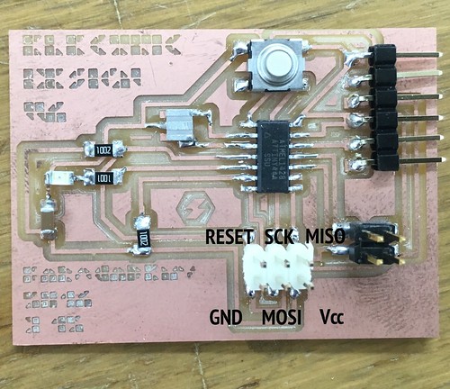
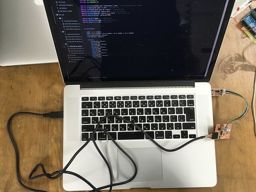
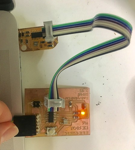
How to Connect PC and FabISP and Hello Board
1. connect Hello board and FabISP with 2x3 pin cable. 2. connect PC and Hello board with FTDI 6pin cable. 3. connect the FabISP and PC.(In my case, I just stuck the FabISP to USB port of PC)
How to write the program to Hello board
To write the program to the Hello Board, I opeded the Terminal(for OSX). I had some experiences to use Terminal and knew some Linex command, so this was not difficult.
            cd PATH_OF_PROGRAM
            make -f MAKE_FILE_NAME.make
            sudo make -f MAKE_FILE_NAME.make program-usbtiny-fuses
            sudo make -f MAKE_FILE_NAME.make program-usbtiny
Another Programming with C
Next, I wanted to make program that turns on the LED while I'm pressing the button.
The LED is connected to PB2(2 of Port B).
            #include <avr/io.h>
            #include <util/delay.h>
            #include <avr/pgmspace.h>

            #define output(directions,pin) (directions |= pin) // set port direction for output
            #define set(port,pin) (port |= pin) // set port pin
            #define clear(port,pin) (port &= (~pin)) // clear port pin
            #define pin_test(pins,pin) (pins & pin) // test for port pin
            #define bit_test(byte,bit) (byte & (1 << bit)) // test for bit set
            #define position_delay() _delay_ms(1000)

            #define LED_port PORTB //Port B Output Resistor
            #define LED_direction DDRB //DDRB 1:Output 0:Input
            #define LED_pin (1 << PB2) // use PB2 pin
            #define buttonPin PINA7


            int main(void){
                CLKPR = (1 << CLKPCE);
                CLKPR = (0 << CLKPS3) | (0 << CLKPS2) | (0 << CLKPS1) | (0 << CLKPS0);
                output(LED_direction, LED_pin);
                clear(LED_port, LED_pin);
            	while(1){
                    if (bit_is_clear(PINA, buttonPin)) //If button is pushed (PA7 == 1)
                   {
            		   set(LED_port, LED_pin);
                   } else {
                       clear(LED_port, LED_pin);
                   }
                }
                return 0;
            }
This video shows how it works:
Embeded Programming : Arduino IDE and FabISP
After programming ATtiny with C language, I realized how Arduino system makes things easier.
For this time I used Arduino language and IDE to write program on Hello board with FabISP.
Arduino IDE setting
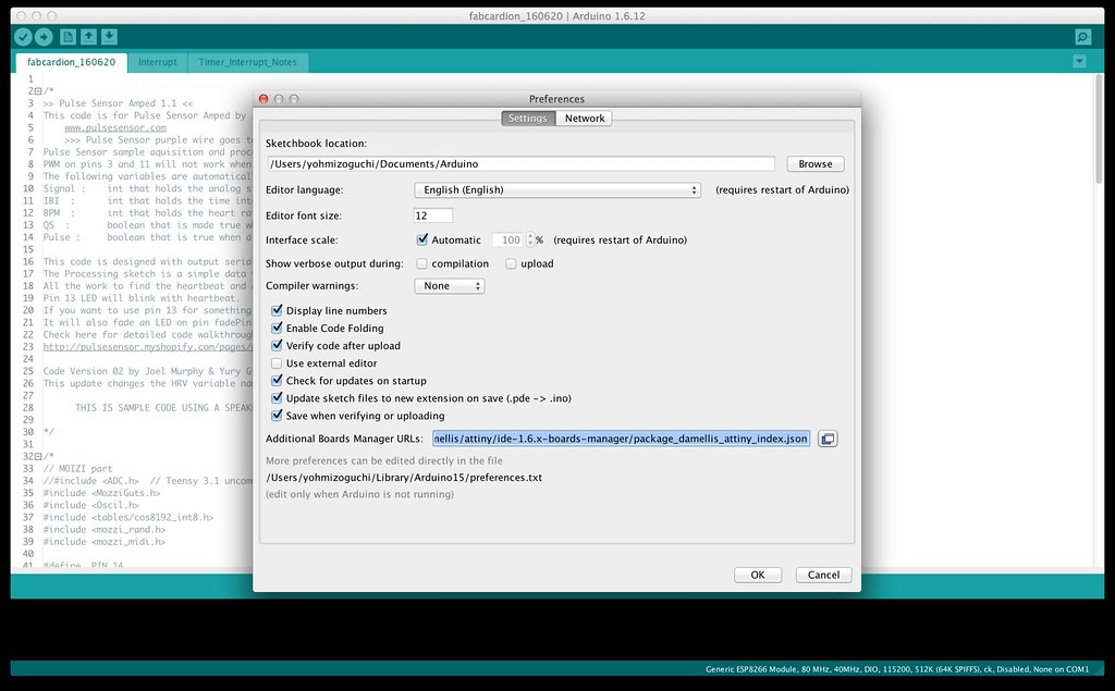
1. Download Arduino IDE
2. Open preference window. This locates Arduino > Preference
3. To add ATtiny board manager, “Additional Boards Manager URLs” put the following URL, then press "OK"
https://raw.githubusercontent.com/damellis/attiny/ide-1.6.x-boards-manager/package_damellis_attiny_index.json
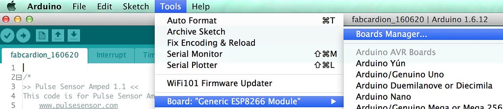
4. Open the boards manager in the Tools > Board
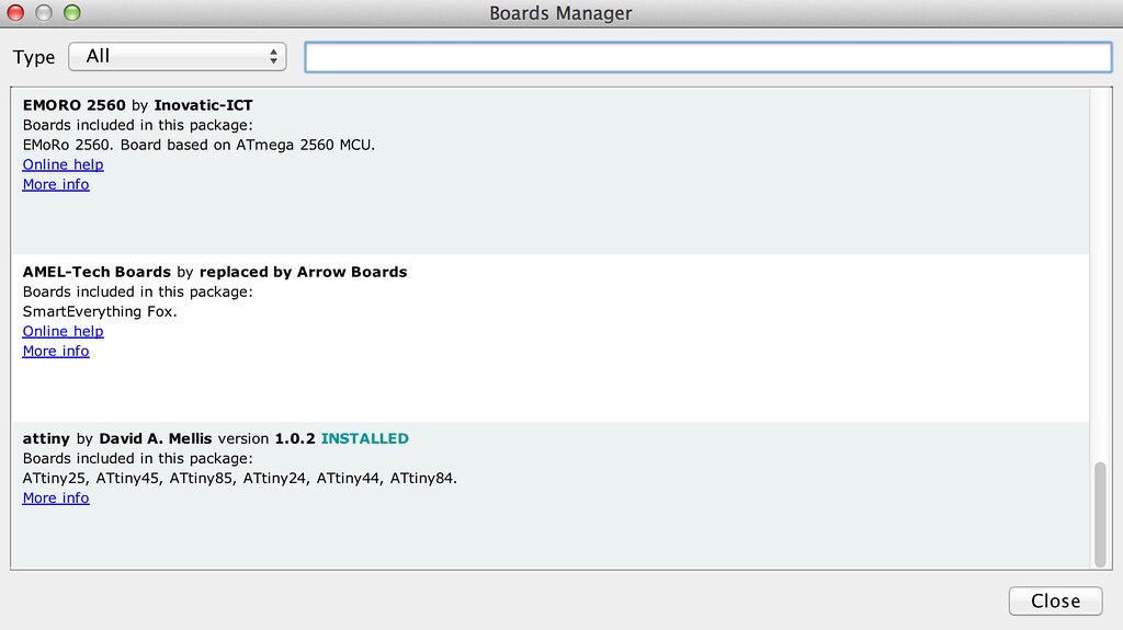
5. Find “attiny” at the bottom of the list and install it
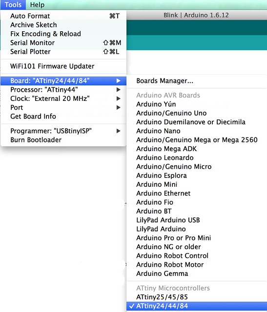
6. In Tools > Board menu following lists are available on your Arduino IDE
7. set the each parameter like following:
- Boards : ATtiny24/44/48
- Proecssir : ATtiny44
- Clock : External 20 MHz
- Port : select the port that is used for FabISP
- Programmer : USBtinyISP
How to connect FabISP and Hello-board
Connect the FabISP and Hello board. This process is same as programming with C.
Programming with Arduino IDE
First do "Burn Bootloader" in the bottom of Tool menu. It took a moment to finish burning bootloader.
Once finishing burning bootloader, I could write program with IDE like normal Arduino board.
I modified the example program "Fade" for the board. The led on the board is connected PB2 = 5 pin of ATTiny44 = 8 pin of Arduino.
So, I changed the led assignment to Arduino 8 pin like "int led = 8; ".
I changed the parameter "fadeAmount" to "10" from "5" because I wanted faster fade of LED.
Here is the Arduino program:
            int led = 8;           // the PWM pin the LED is attached to
            int button = 7;
            int brightness = 0;    // how bright the LED is
            int fadeAmount = 10;    // how many points to fade the LED by

            // the setup routine runs once when you press reset:
            void setup() {
              // declare pin 9 to be an output:
              pinMode(led, OUTPUT);
              pinMode(button, INPUT);
            }

            // the loop routine runs over and over again forever:
            void loop() {
              // set the brightness of pin 9:
                analogWrite(led, brightness);

                // change the brightness for next time through the loop:
                brightness = brightness + fadeAmount;

                // reverse the direction of the fading at the ends of the fade:
                if (brightness <= 0 || brightness >= 255) {
                  fadeAmount = -fadeAmount;
                }
                // wait for 30 milliseconds to see the dimming effect
                delay(30);
            }
Here is the video how to upload and how the program works:
Next step to learn
How to write a program to Hello board with Arduino board.
Learn more about C programming.