In this class, I made fabkit to observe whether it can sense correctly.
I reffered this website and made data by myself.
Making data For Fabkit
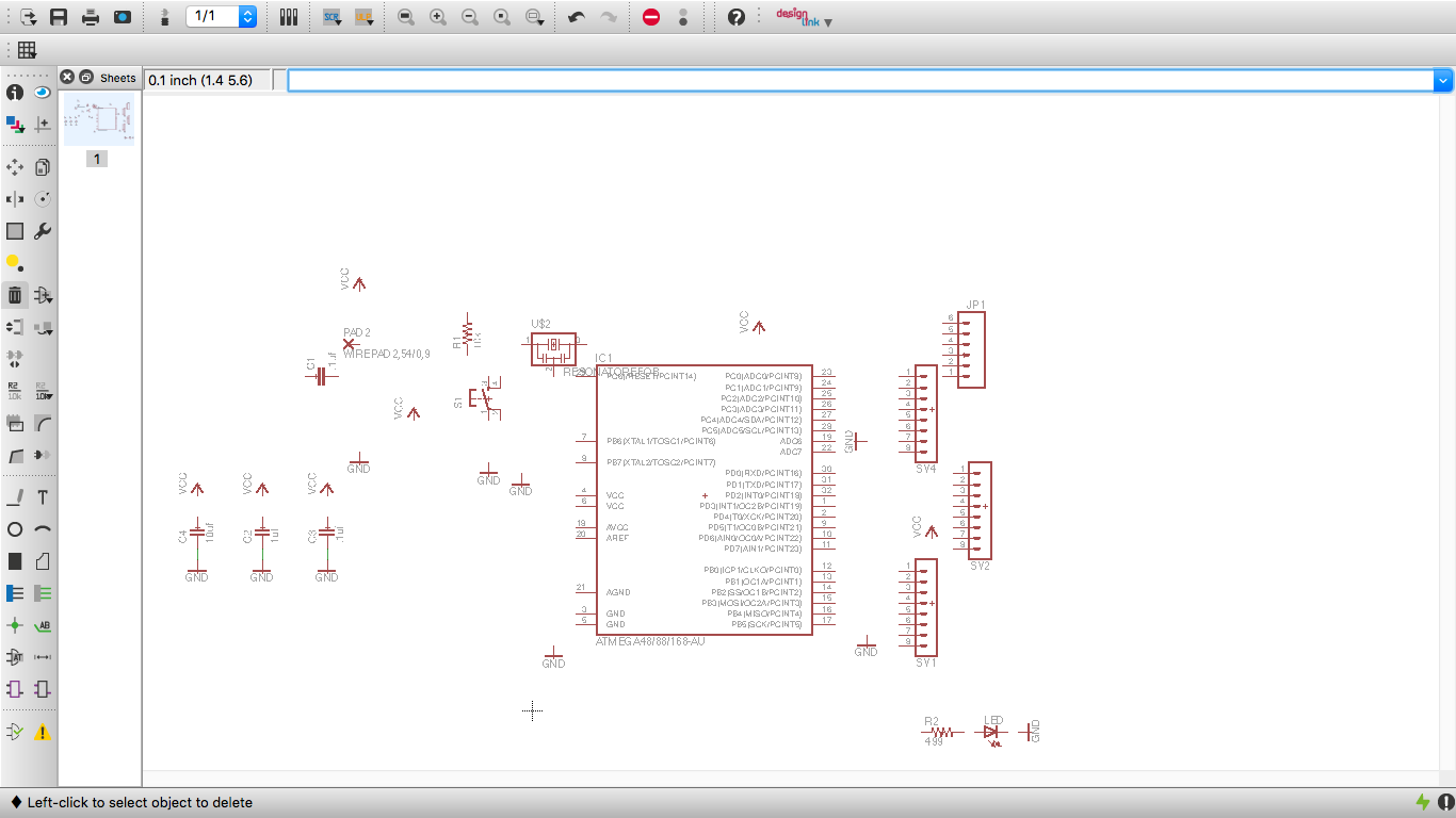
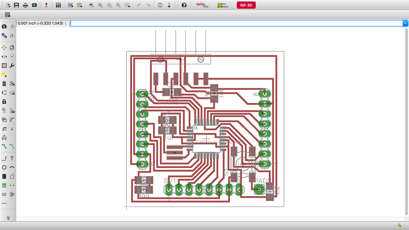
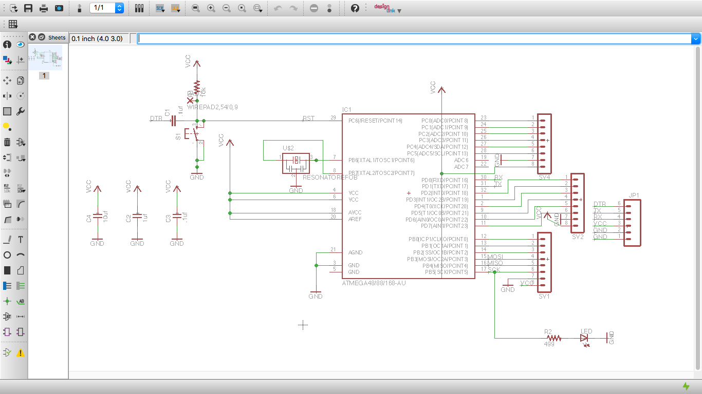
At first I placed parts necessary for making fabkit.
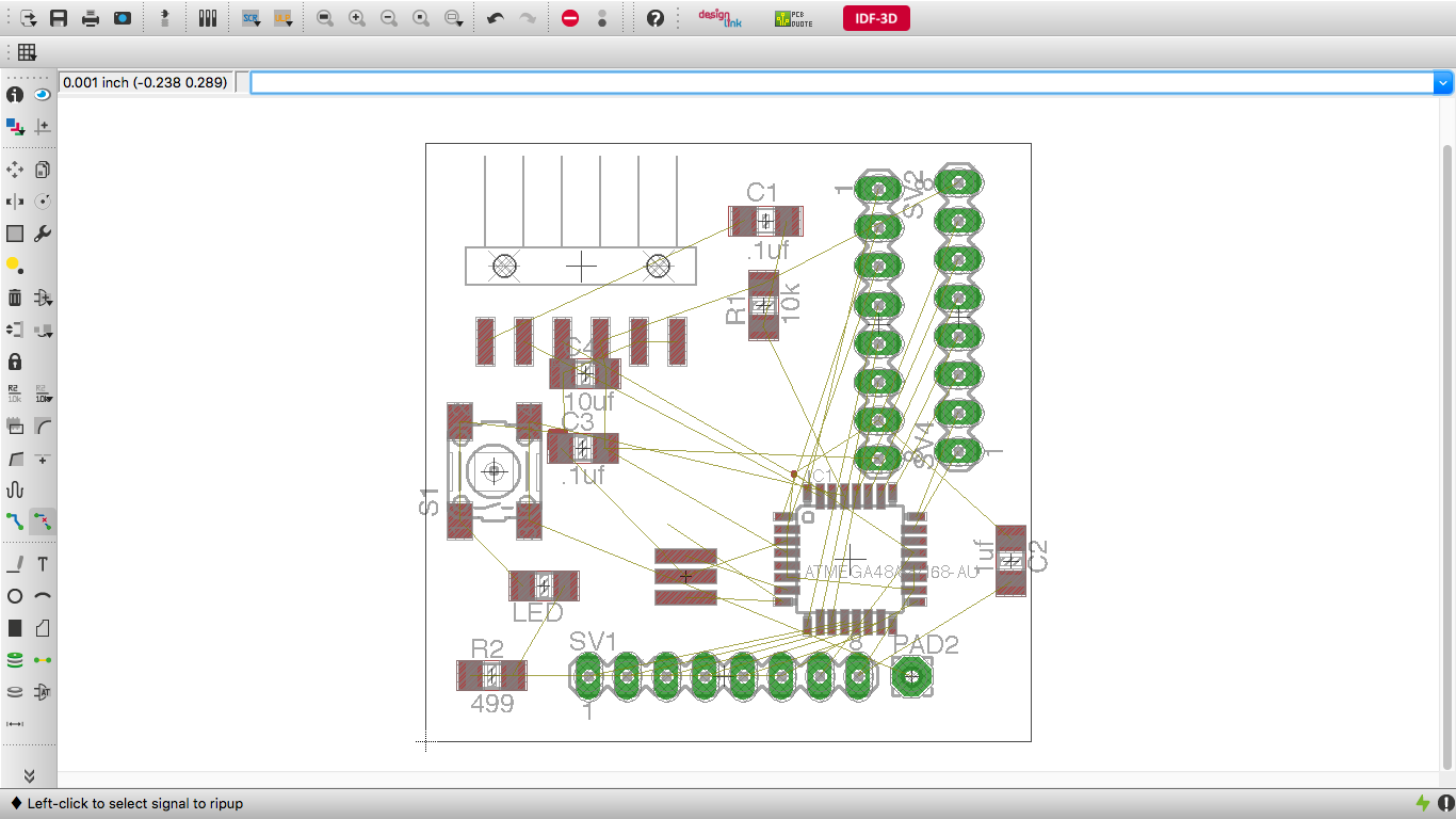
Here is the picture of placement in both board and schematic display.
Unlike week6, fabkit needs to be cut and it should have some halls.
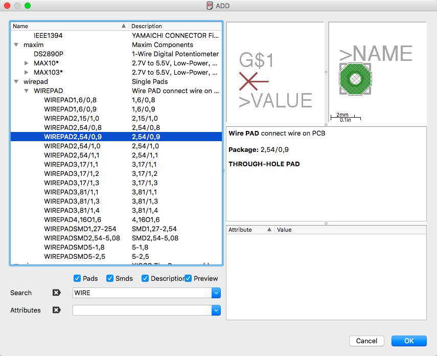
Pad is one of the example.
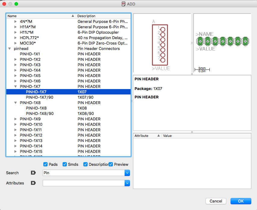
And it's also true of the pin header
And I connect the pins and place them in a small square.
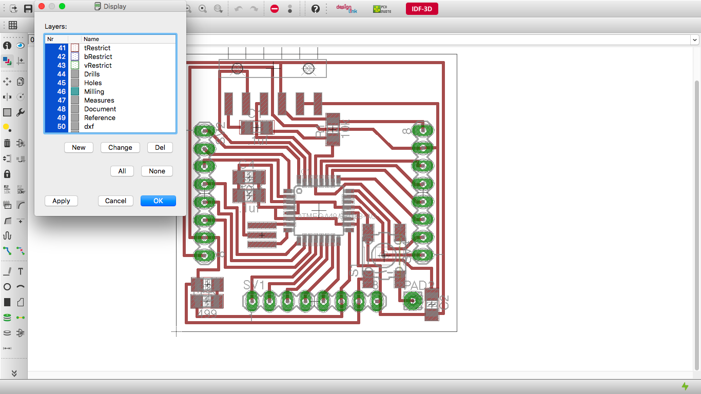
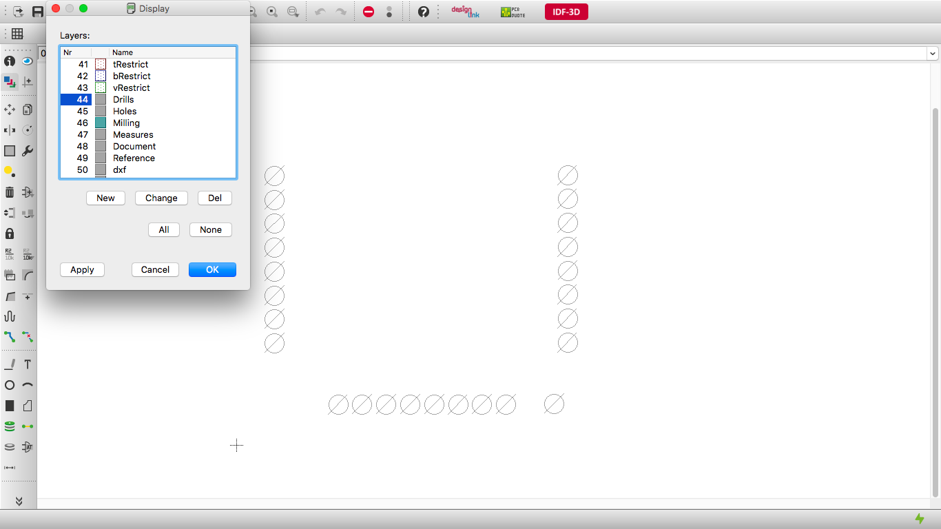
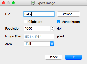
For making hall png data, I changed the mode and edit the color settings in Eagle.
And I exprt it to png file.
After that I edit the file using illustrator.
That is how I made the data for fabkit.
making the board by Milling machine
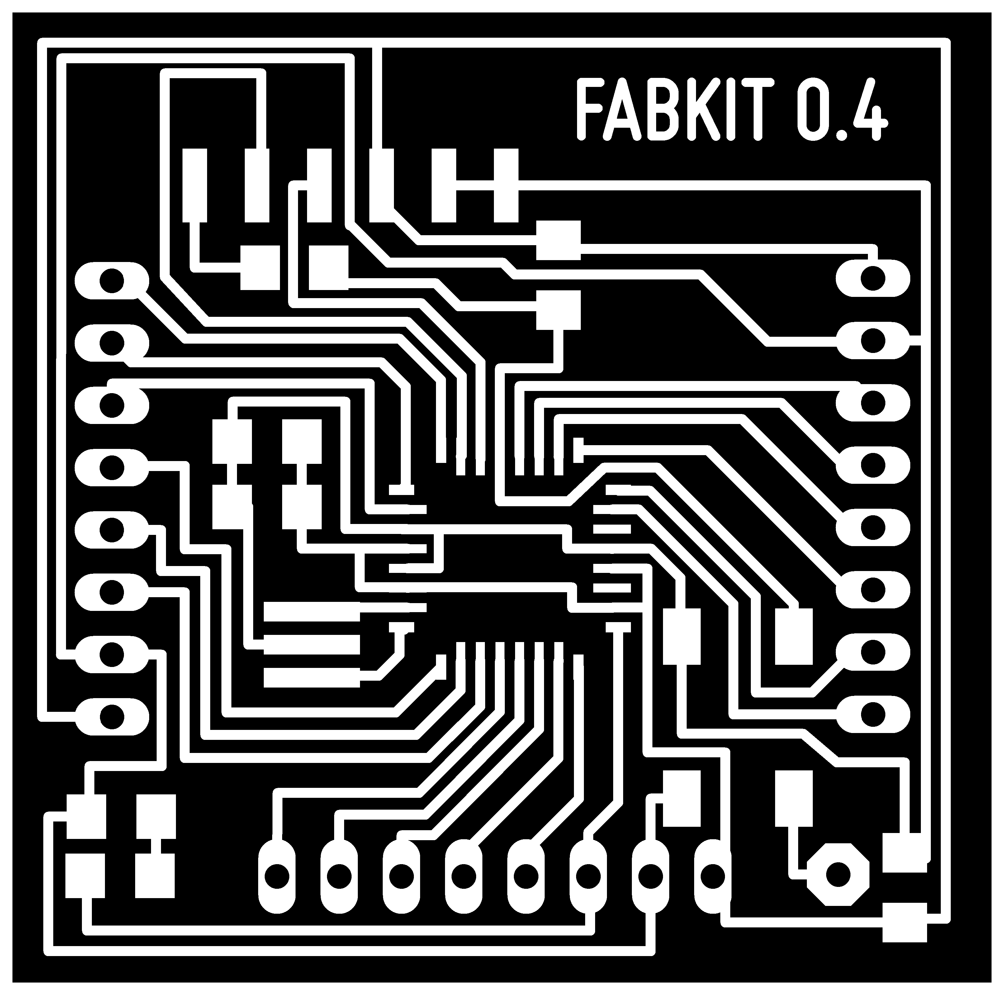
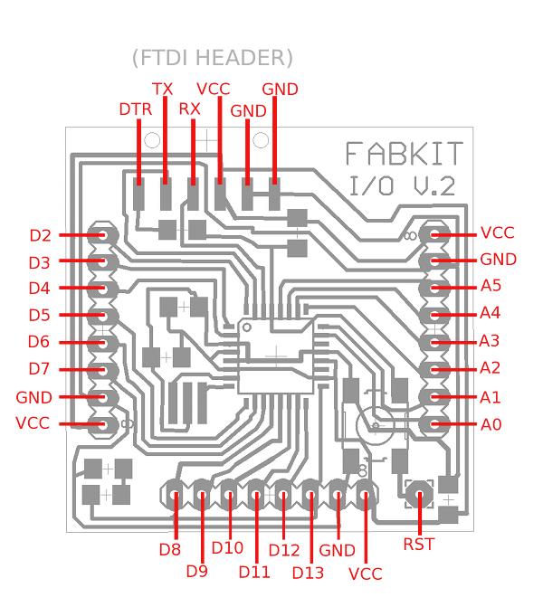
Here is the picture of traces for making fabkit.
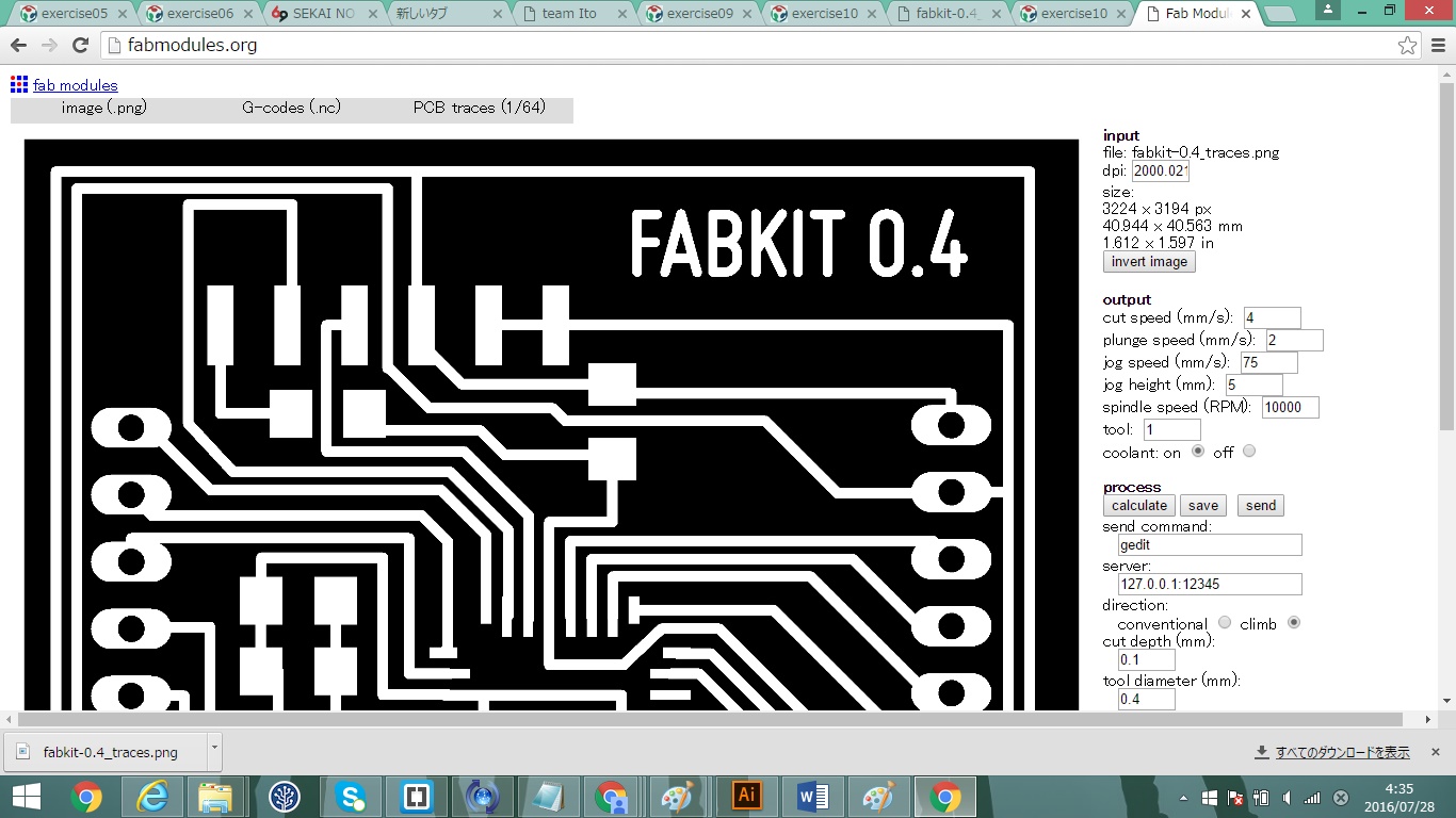
And I loaded it in fab modules and made .nc data for milling the PCB board.
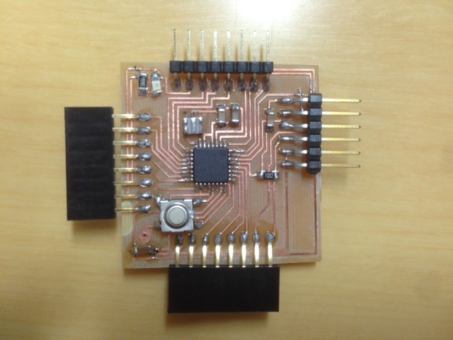
After milling the PCB board, I soldered the parts and I could made fabkit.
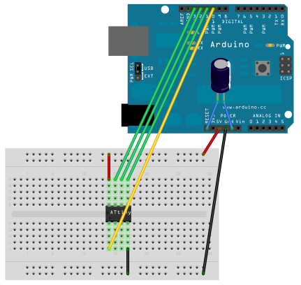
Rather than datasheet, I reffered this website for learning how to connect.
Here is the way to connect arduino as ISP and attiny in this page , and the idea is almost the same with my assignment that this picture helped me so much.
Audio input
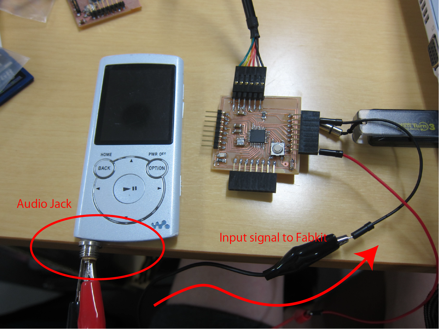
Here is the system of my input device.
Audio Jack funcntion as a input device for audio input.
The function is related to my final project.
Fabkit recieve the signal from walkman and send the information to serial monitor.
You can see how it works here.
And here is the code for fabkit.
I improved the code and increased th baud rate so that I could observe how it can sense more accurately.
	   void setup() {
       Serial.begin(115200);
    while (!Serial);
    }

    void loop() {
    int val = analogRead(A0);
    Serial.println (val);
    delay(50);
    }