Exercise06
Electronics design
In this class I learned how to use Eagle and about making an electrical circuits.
As an assignment, I made the board which has a LED and switch and connection pin.
By programming, I can control the LED and make it communicate with the other device.
My local tutor told me the basic schematic of the board, and I designed it by myself using Eagle.
Eagle: Making a schematic

At first I dowloaded eagle from here

After downloaded, I created a new project and added a new library.
In the library, there are a lot of data about electrical parts needed for making electrical circuit.

I picked up the electrical parts needed for my project and placed them on the display.

This is the completion drawing of my electrical circuit.
That's all about making a schematic.
Eagle: Board design

I changed the display and worked on a board design, using the schematic data I made.
Like this, I changed the thin line into a wide line for board design. I was careful not to overlay the line.
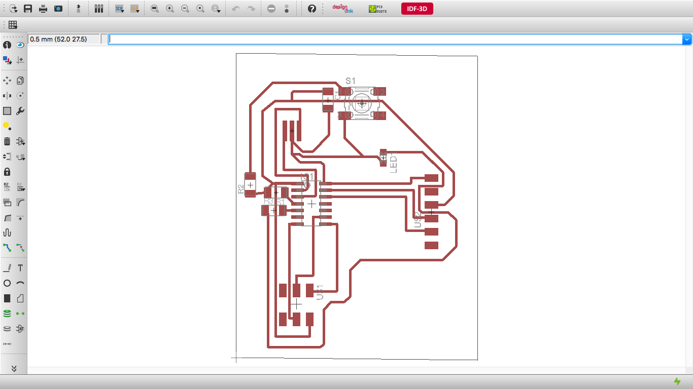
This is how I designed my board design.

After that I output the data as png file and edited it using photoshop for fabmodule.
Cutting the Printed circuit board

I used this machine for cutting; KitMill CIP100.
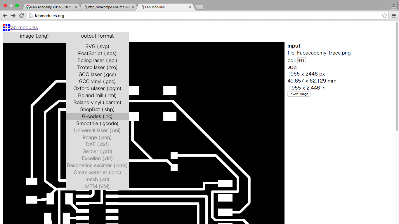
I output the data as nc data.

To make trace cutting data, I changed the tool diameter parameter from 0.4mm to 0.2mm.

I used this drill for the data.

And to make the outline cutting data, I changed the number of offsets from 1 to -1.
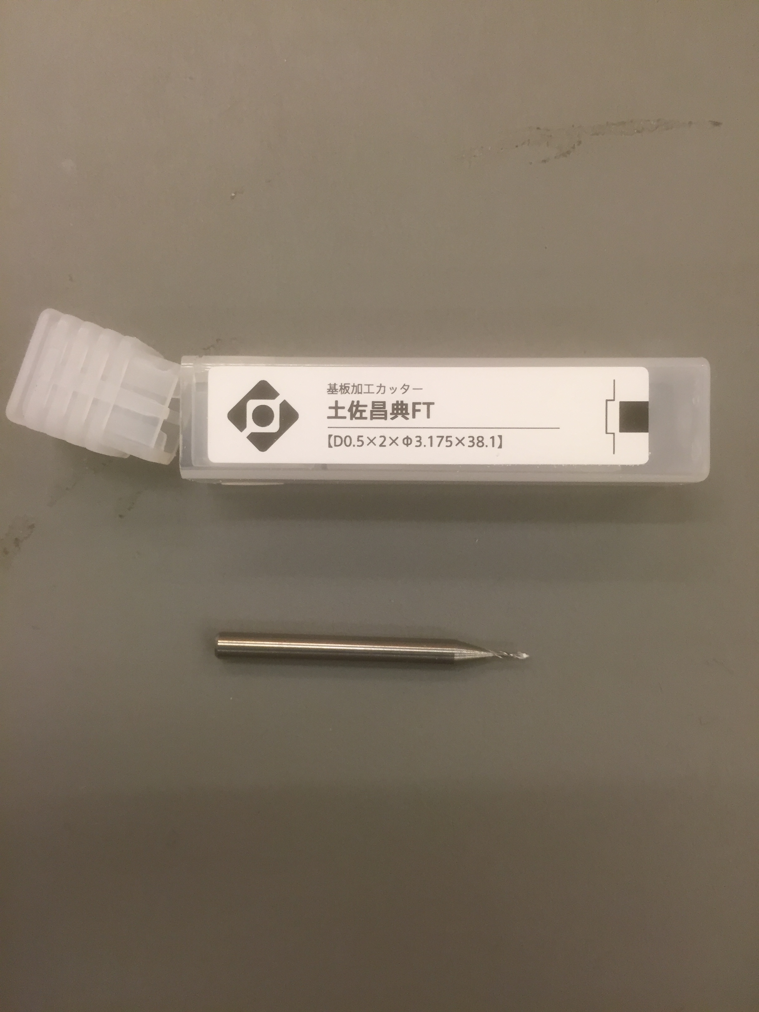
I used this drill for the data.

At last I could cut the PCB.
I was worried that the line of the data was too thin, but it was no problem.

And I attached the button and LED to the board
At that time I found the schematic data I made was wrong.
So I had to make the board again and cut the board.
Here are the right one.


After that I solder it and made the board completely.
download the circuit outline data
download the circuit trace data
download the circuit brd data
download the circuit sch data