Assignment
This week, we learned the use of computer-controlled cutting machinery such as vinyl cutter and laser cutter.The weeks assignment is to design and create a press-fit construction kit along with the use of a vinyl cutter.
Vinyl Cutter
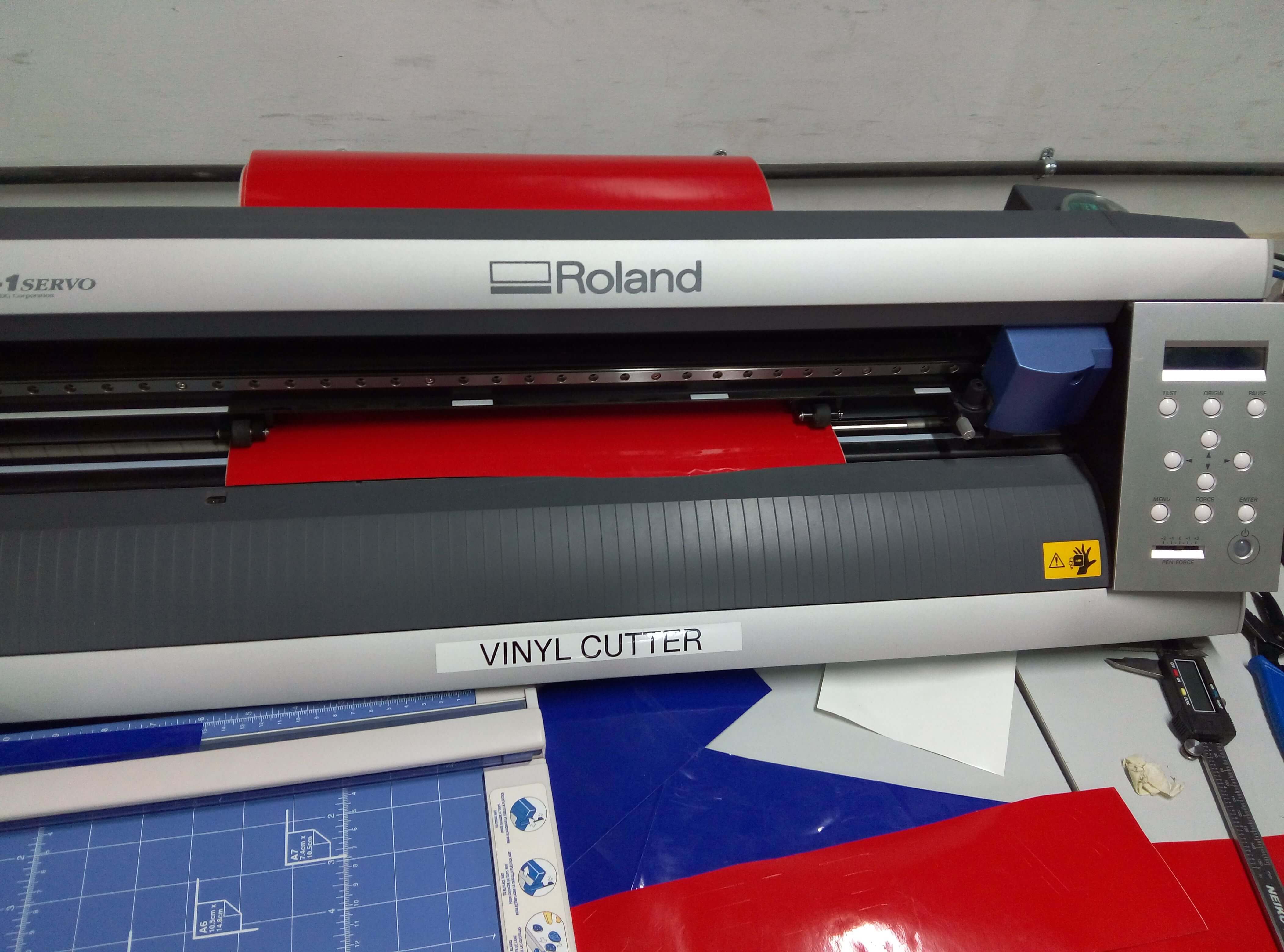
A vinyl cutter can be used to design stickers and designs by cutting vinyl sheets. In our lab, the software used for cutting is FAB modules. The fab module takes .png as input and create a vector path for cutting.Our lab use the Roland gx-24 camm-1 servo vinyl cutter.
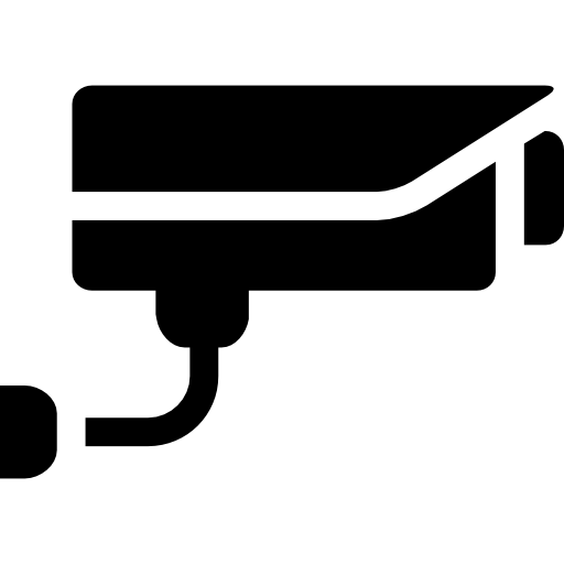
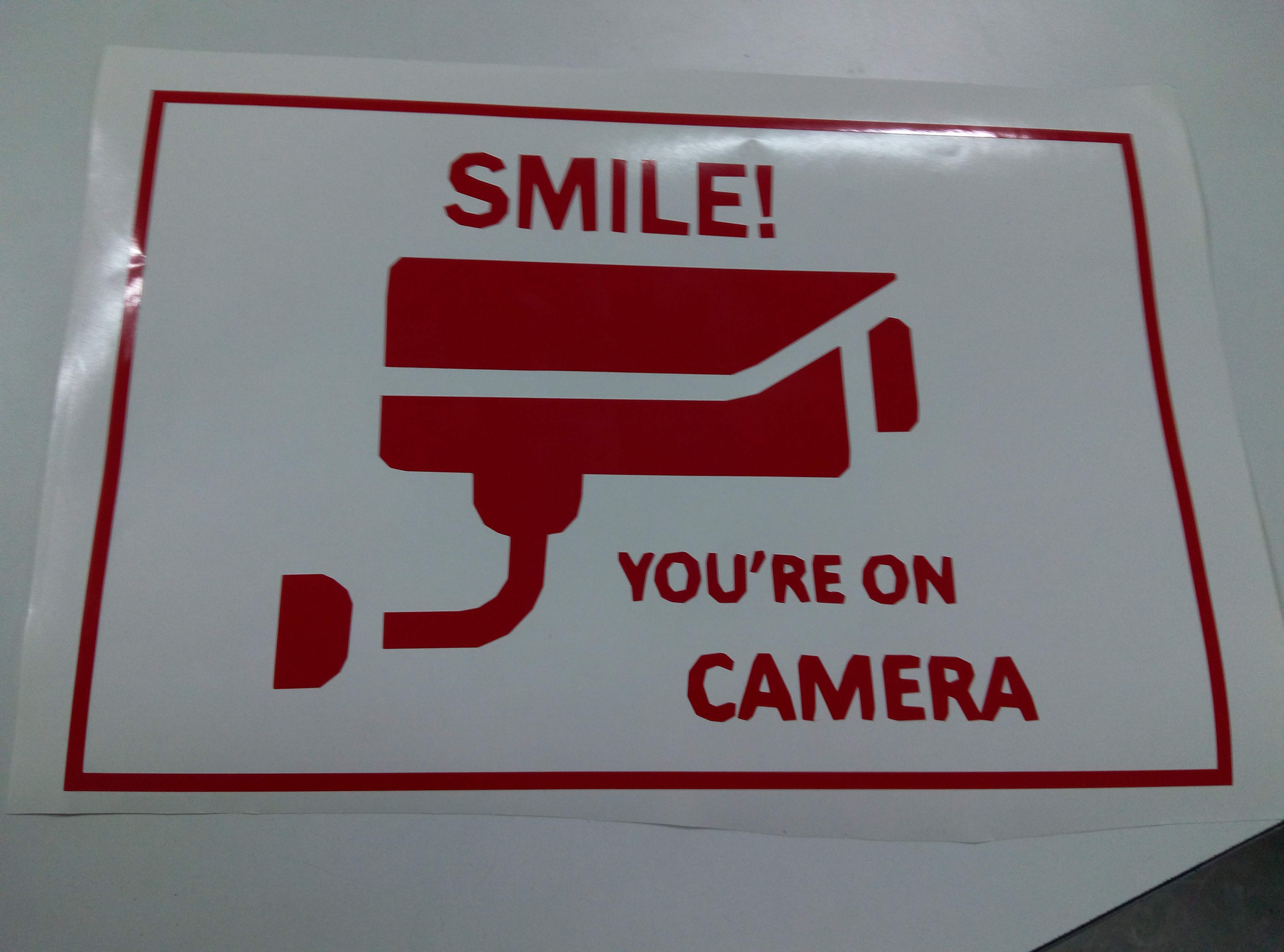
I wanted to create a CCTV CAMERA SURVEILLANCE sticker for our Fab lab. So first i downloaded a CCTV Camera image(in .PNG) from google images.
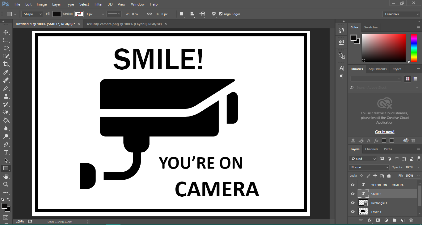
Then i used photoshop to create and integrate the warning message with the image.
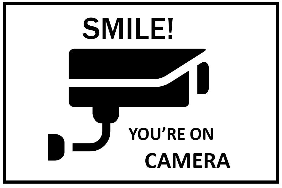
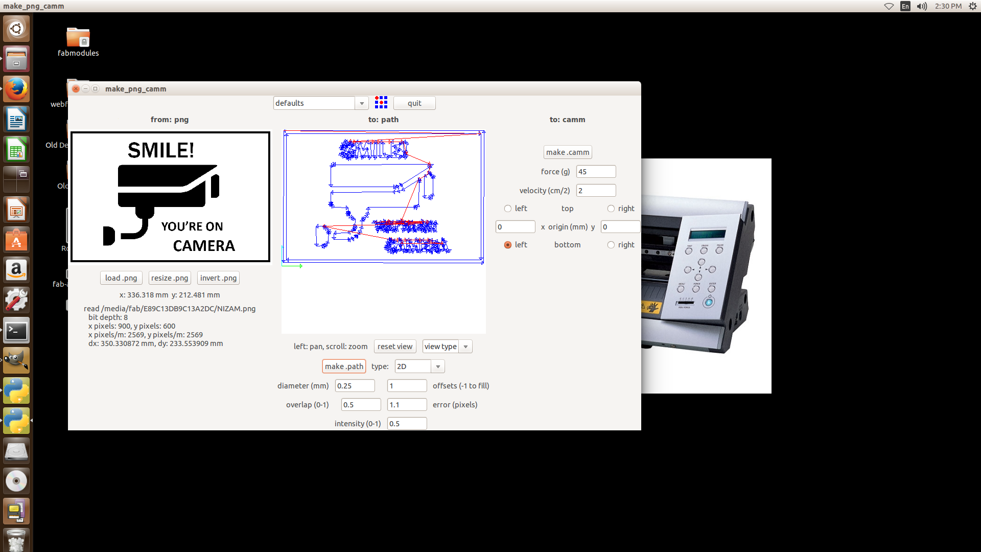
This .PNG file was loaded into the FAB Module for cutting operation using the following steps:
- Load the .PNG using the load button in the Fab module.
- Make sure the vinyl sheet is placed correctly in the vinyl cutter and centre the origin point.
- In the Fab module, Select the material type as vinyl sheet.
- click make.path. This will obtain us a vector path the cutting process will follow.
- Click on the make.camm button and click send!!!
Now we need to remove the skelton sticker from the vinyl sheet.
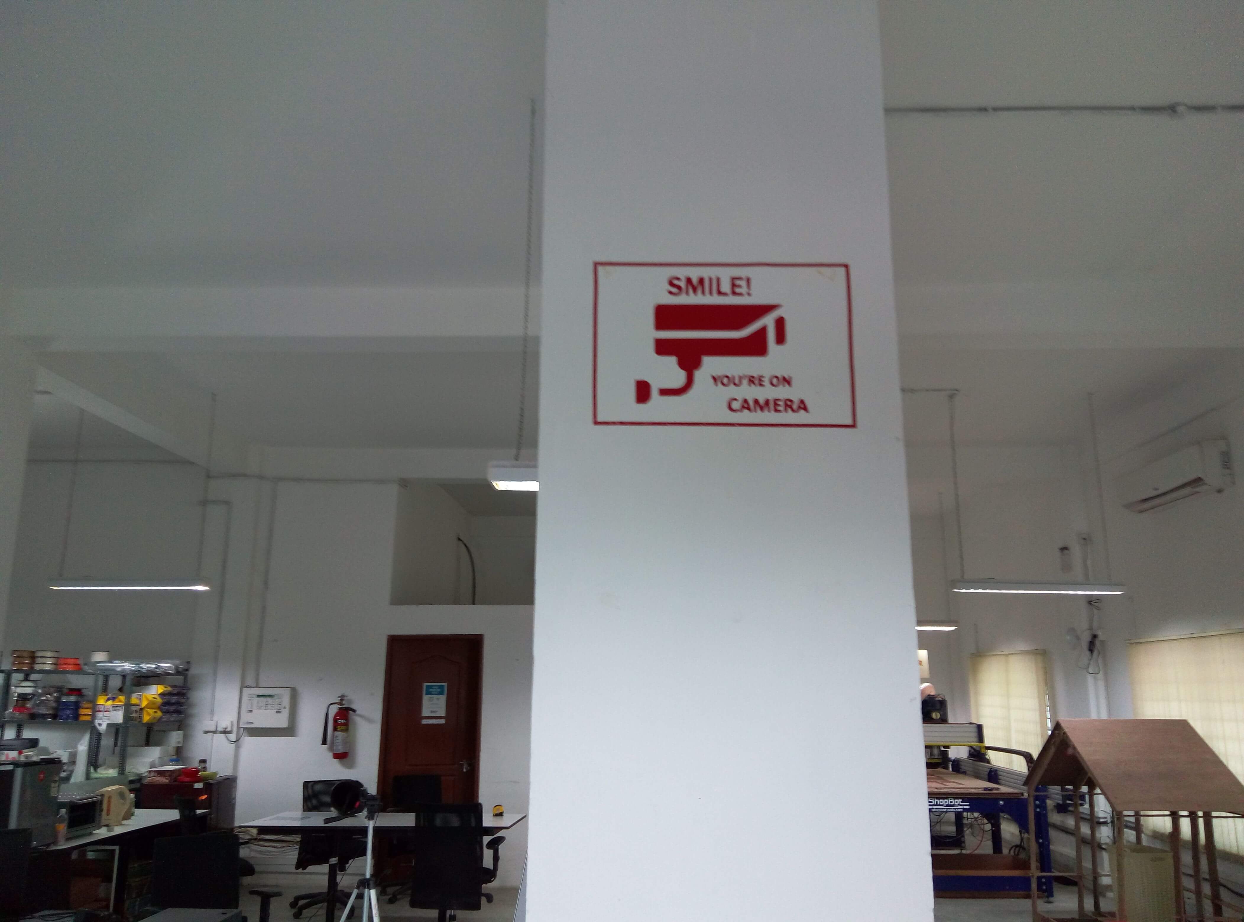
The best way to paste the sticker on the required surface is by sticking a masking tape on top of the vinyl sheet and then remove the masking tape from the sheet such that the vinyl sticker stick to the masking tape.The masking tape is then sticked to the required surface and removed carefully such that the vinyl sticker sticks to the surface.
File in .psd format- cam.psd
Press Fit Using Laser printer
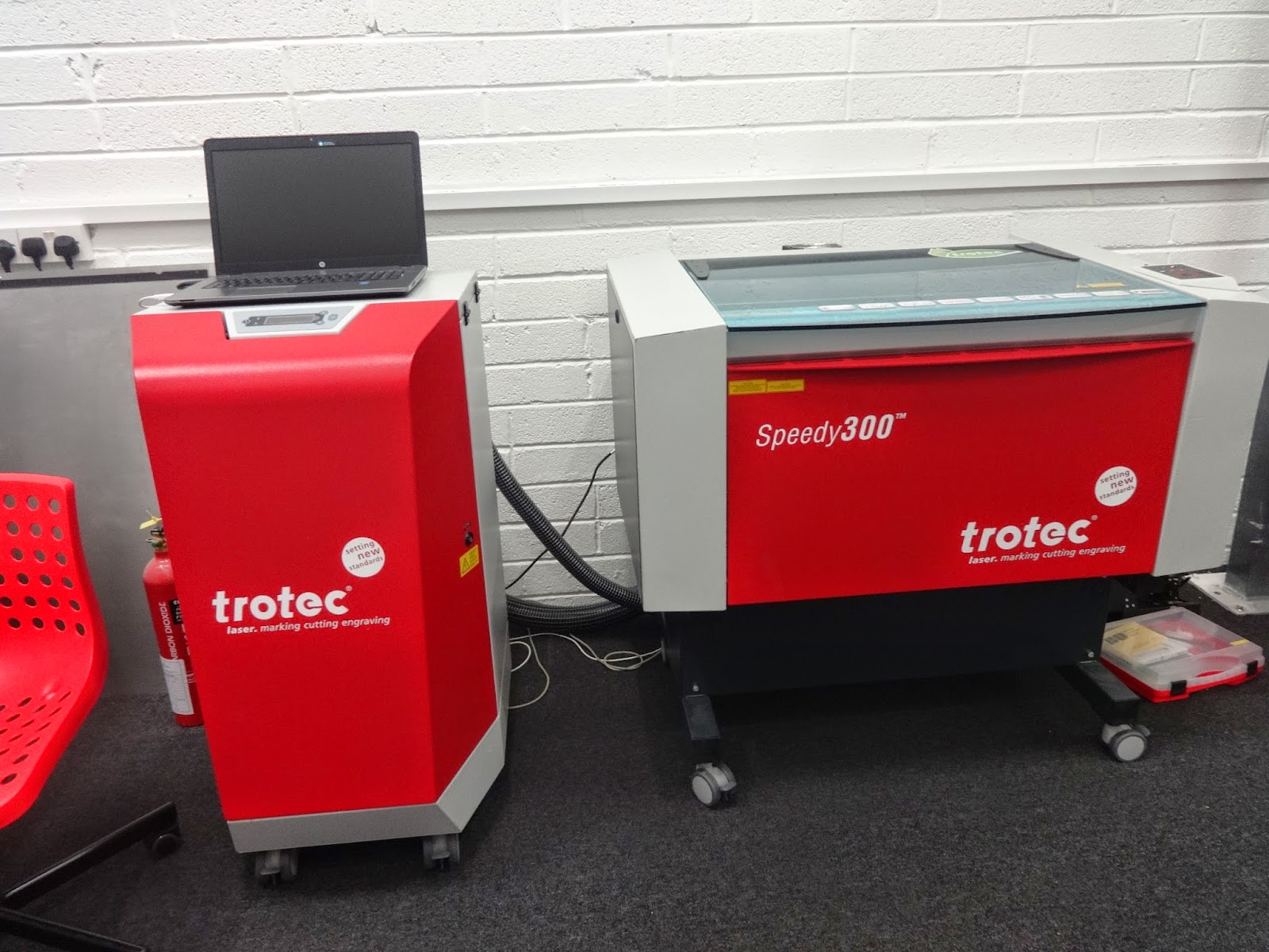
A laser cutter can be used for either cutting or engraving on a variety of objects such as wood,
acrylic,metal,glass etc.Our lab contains the trotec speedy 100 laser cutter.As the name suggests,the laser cutter
use concentrated laser beam for its operation. The focused laser beam is directed at the material through lens,
which then burns the material in the defined path.
The laser cutter can take as input multiple types of files but i found it best to use JPEG and SVG as input formats.
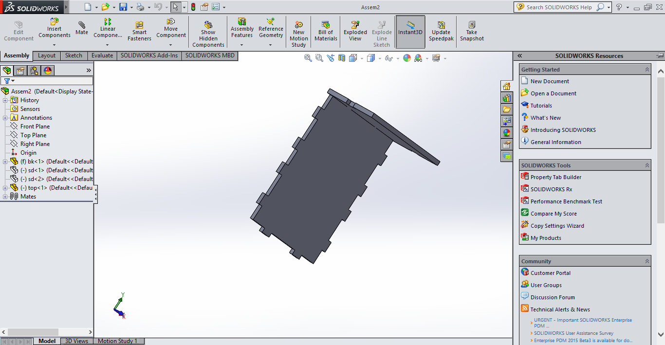
I designed my file using solid works and saved it in .SVG format.I wanted to design something simple and after some
pondering, I decided on a press-fit box, mainly as a display for fablab visitors.
The file can then be printed using the print option. In the print menu, select the laser cutter as printer and click
print. This will open the job control software. Job control controls the laser printer operation. The speed and
power of the laser can be adjusted according to specification using job control. The material to be printed on is
also selected in job control.Each material will have a predefined speed and power setting but it can be manually
changed if necessary.The position and starting point can also be set using the laser cutter.
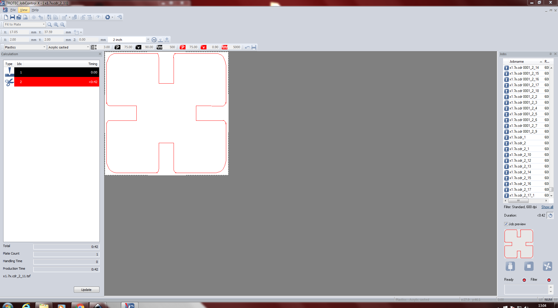
Another thing to note is that, by default, Red is for cutting operation and black is for engraving operation.
The machine will perform the action accordingly whenever it encounters the red and black colour.
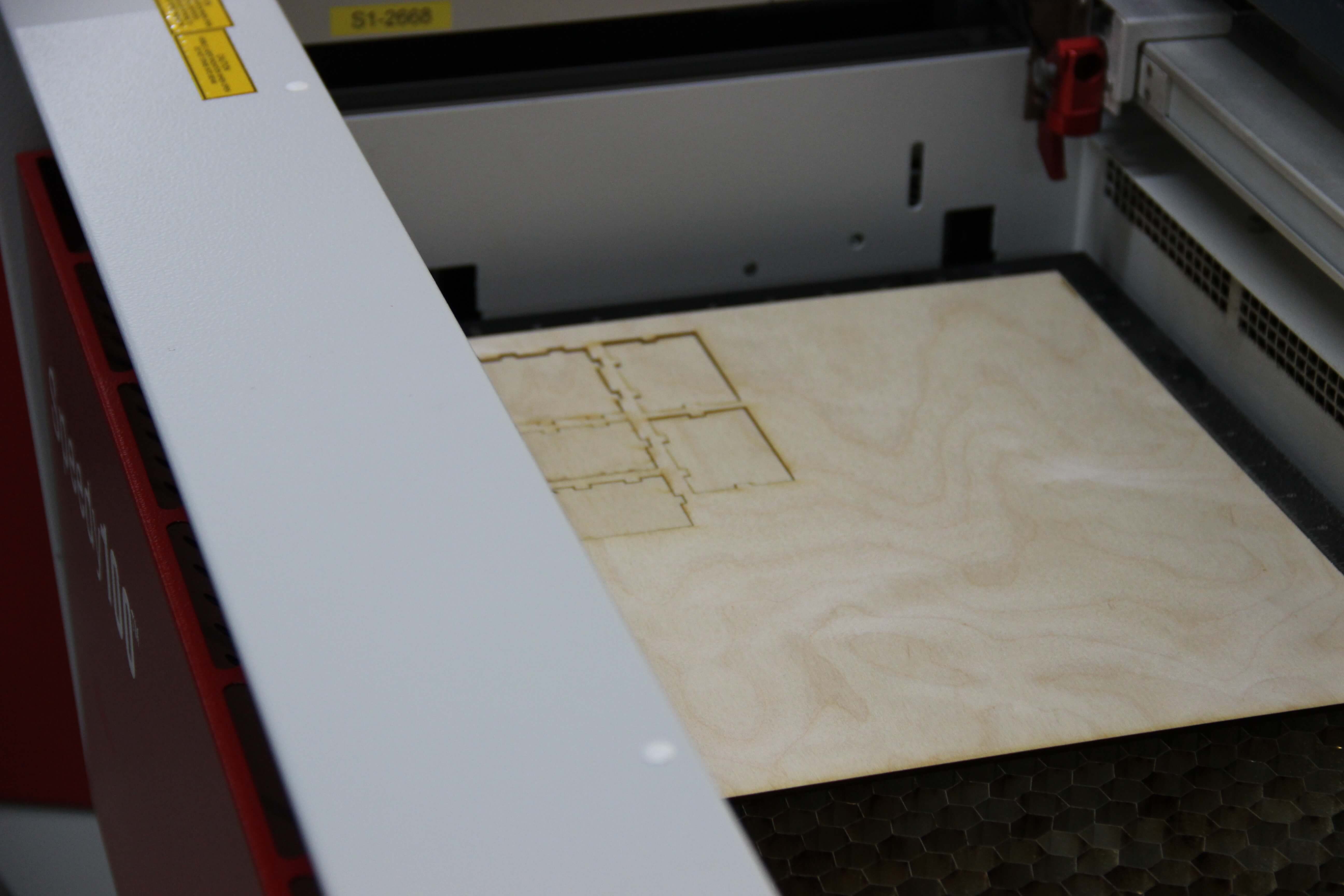
To print, in job control, click ready, set the position and click start.Before printing, make sure that the laser
is focused correctly using the focusing tool.Clicking the start button will start the printing. The eshaust machine
should also be on so as to suck the fumes from the laser machine. Now sit back and watch the laser operation.
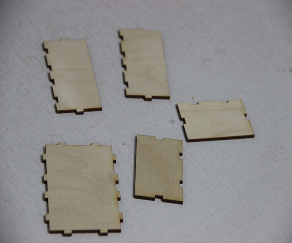
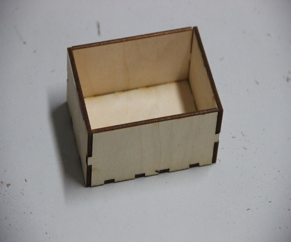
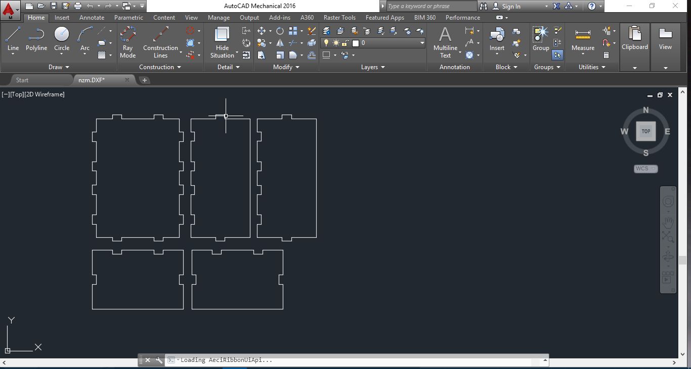
.DXF File PRESS FIT BOX
UPDATE(26/07/2016)
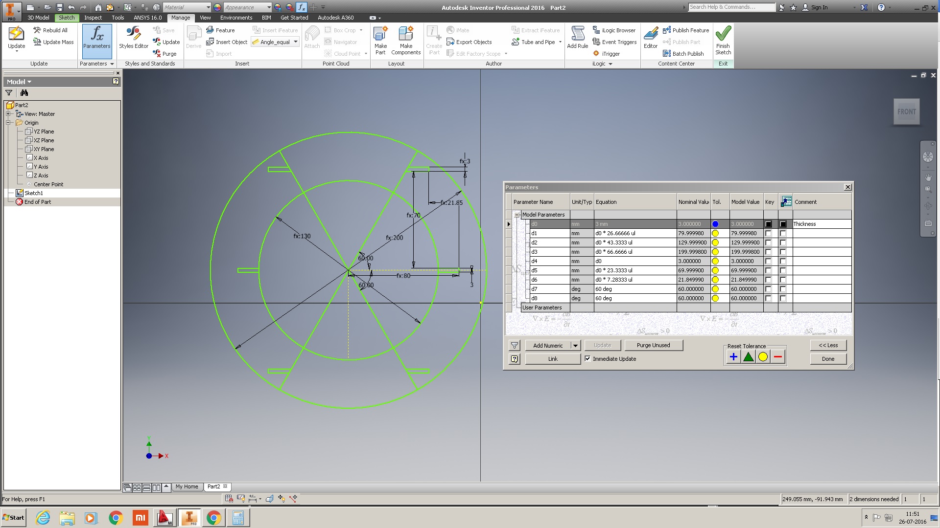
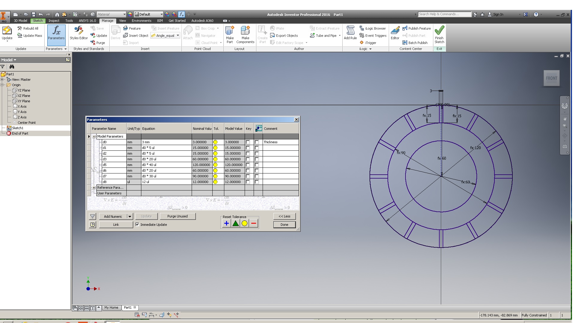
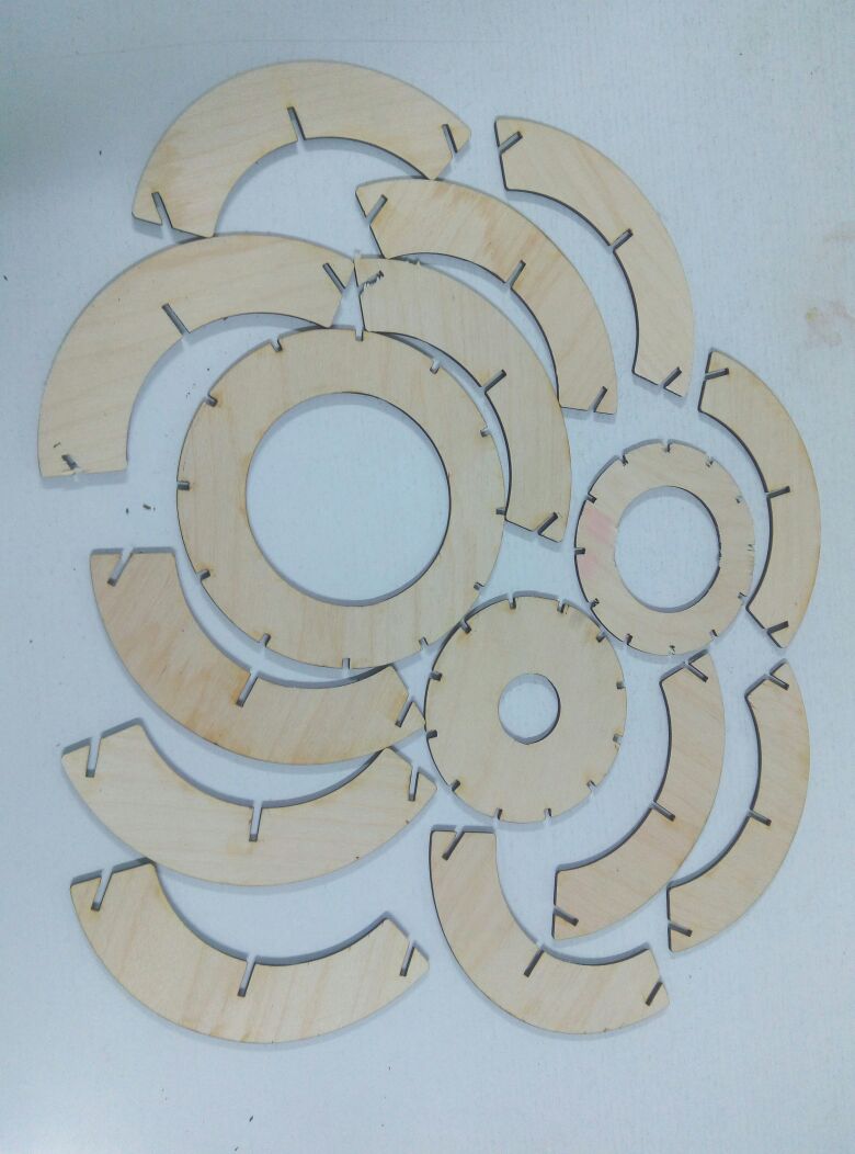
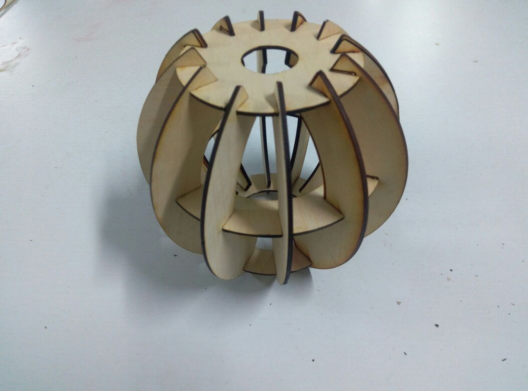
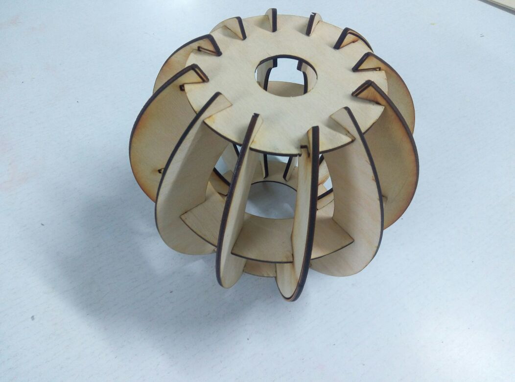
The press-fit box was not a parametric design. So i made another design. This time, i decided to use Autodesk inventor and automatic mechanical to make the design.The design was that of a light fixture.
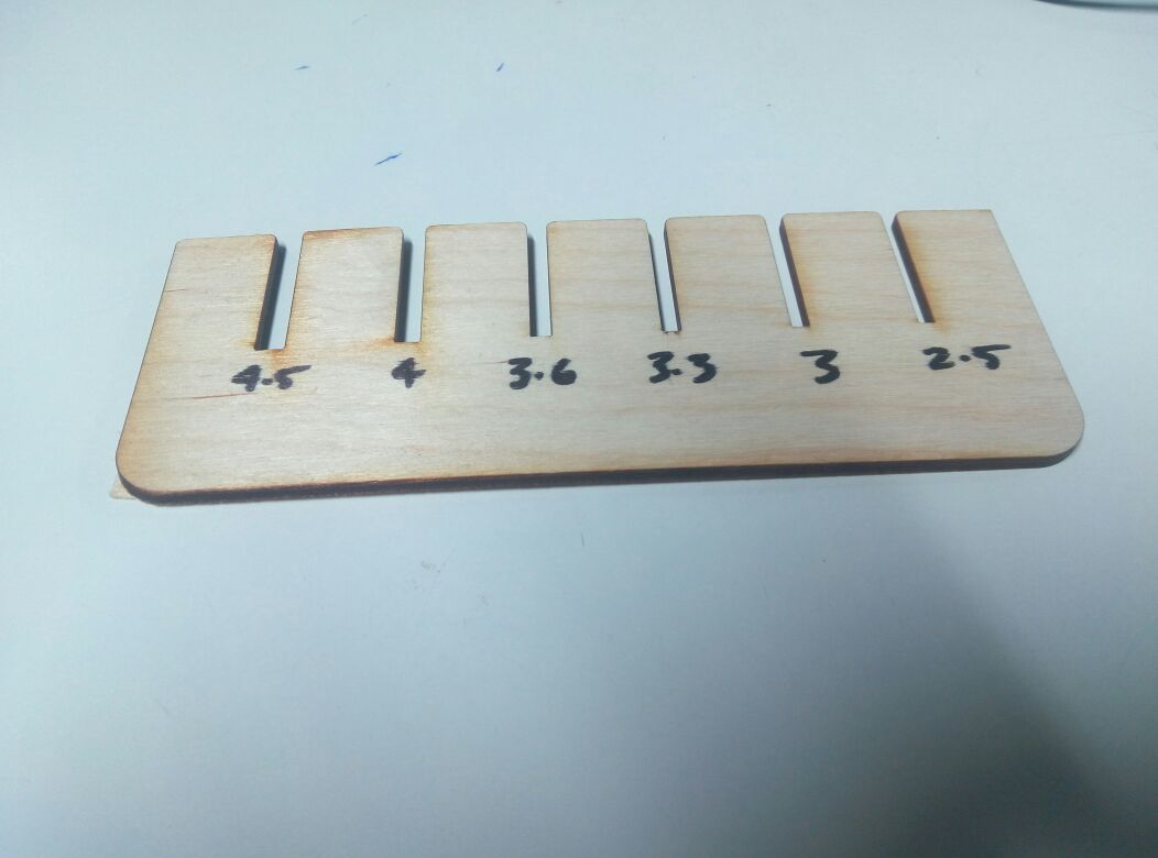
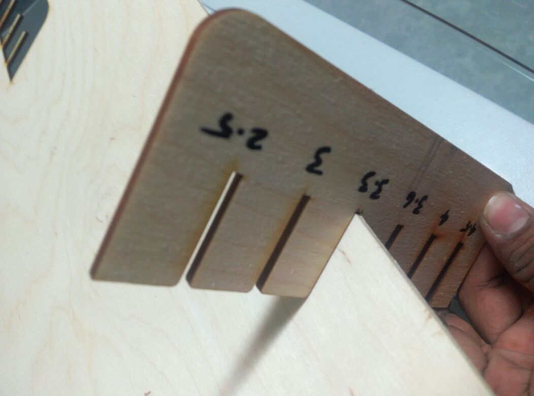
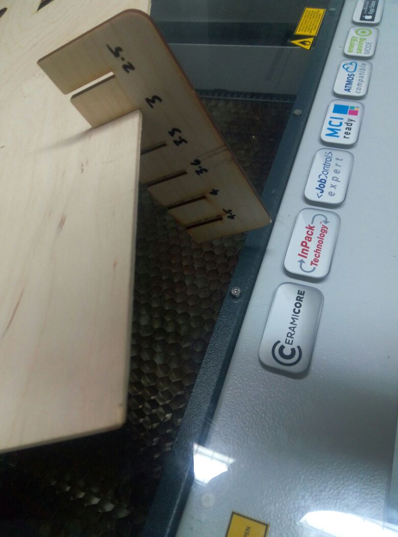
First i needed to measure the size(thickness) of the of the material i will be using.For this, i designed a comb scale, which contained slots of different sizes.
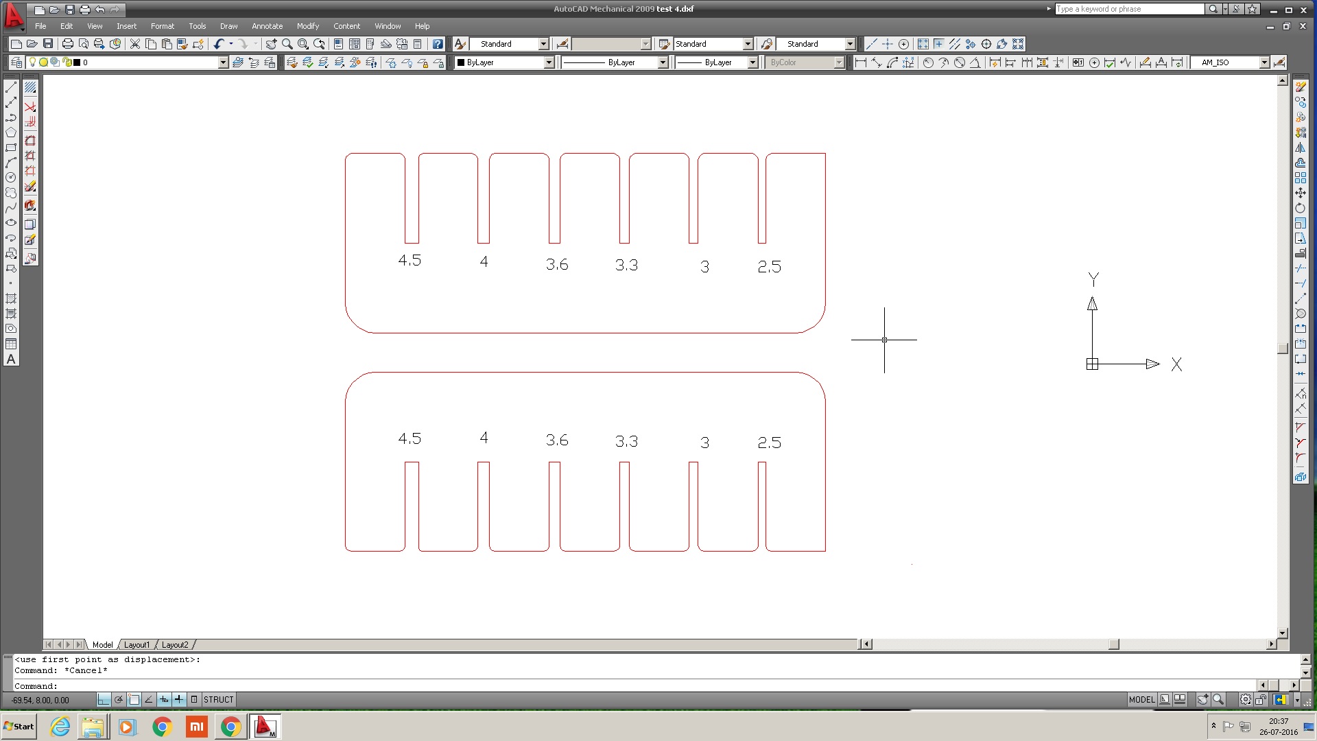
(600 x 300) and arranged the design parts compactly.
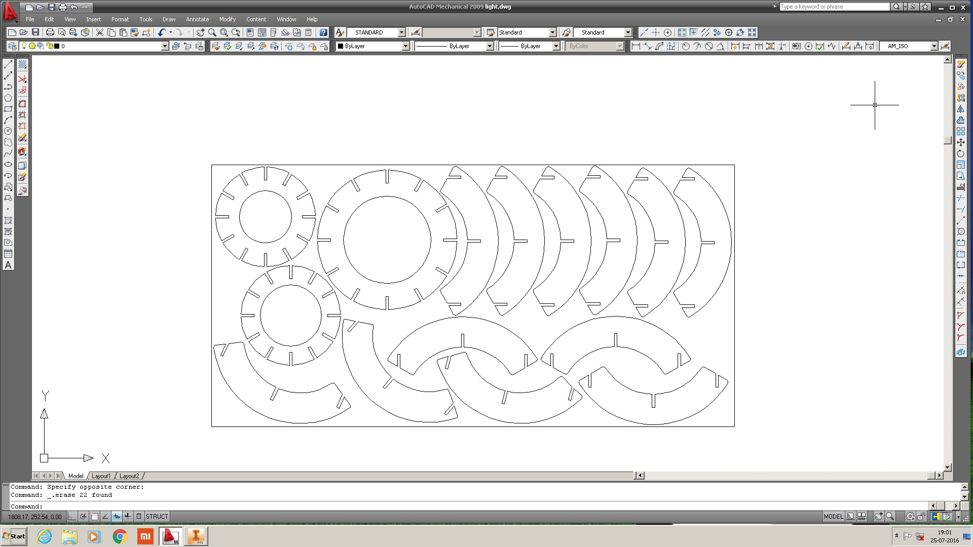
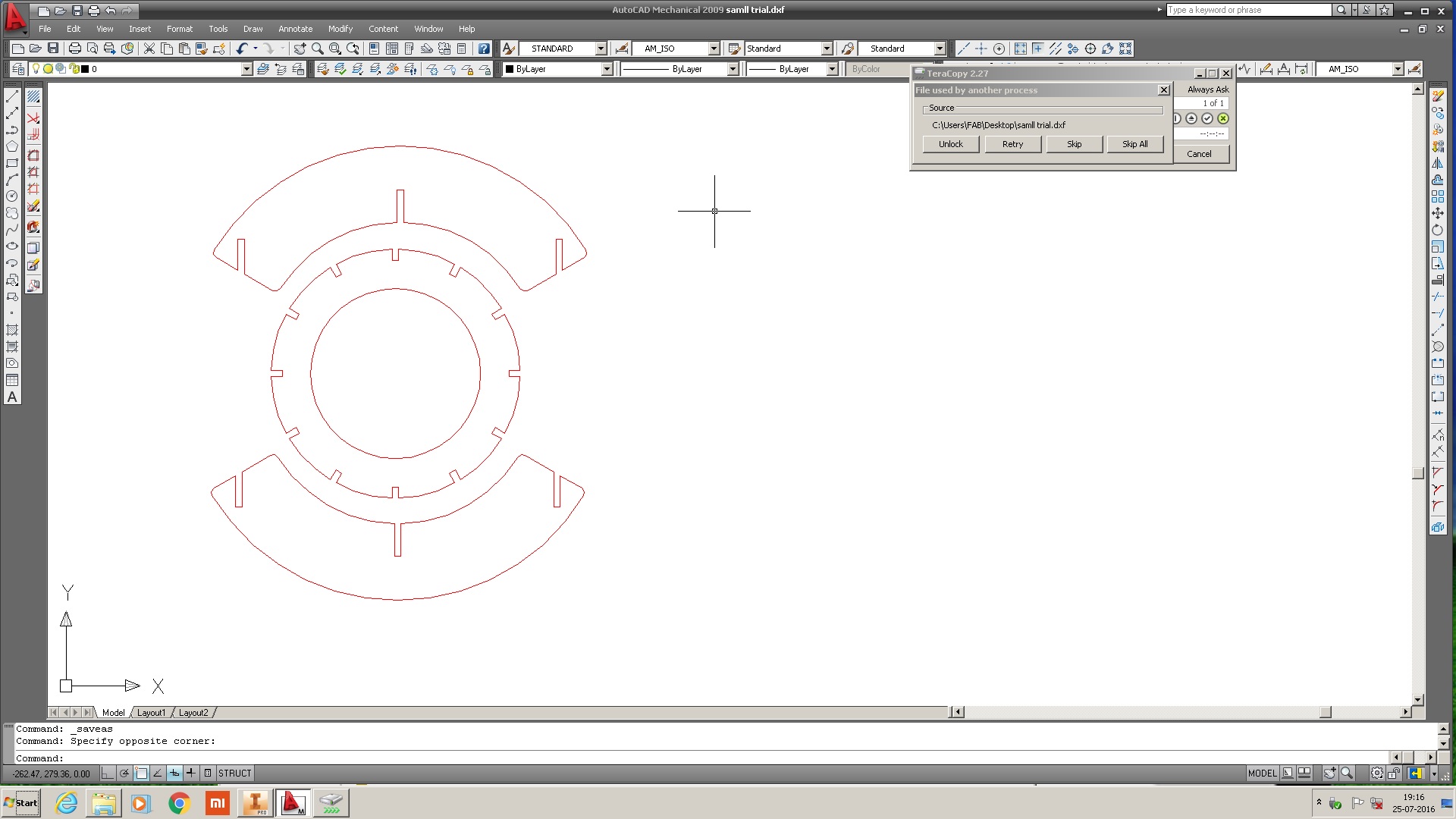
Download design files(Inventor & Autocad)- light fixture