measure something: add a sensor to a microcontroller board that you have designed and read it.I decided to redesign Neil's phototransistor board for light measurement.ATtiny 45 microcontroller is used, and so i first read the Datasheet which is really important to understand how it works.
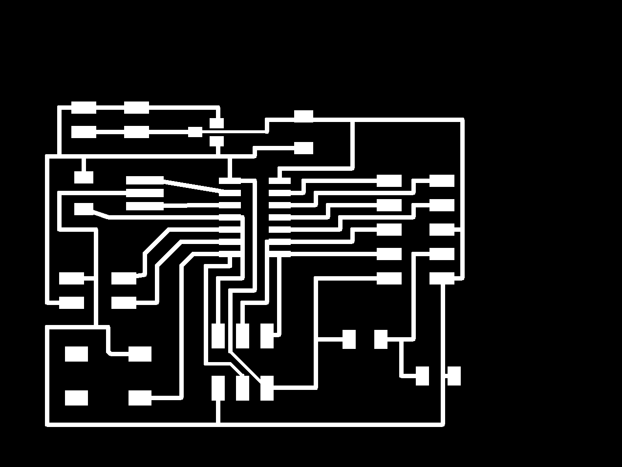
Using the image of neils board, i designed the phototransistor board using eagle software. I added an LED to the board to indicate certain
levels of light.
Next came the milling and stuffing part.I milled the board using the rolland MDX-20 and then stuffed the board. It was fairly easy and didnt take much time.
In the programming phase, I first tried to programme the board using Neils code.This was to check if there was any problems in the old connection.Lucky for me, no errors showed during programming and the sensor worked fine.
Now i tried the programme i made(edited from neils code) but this time problem occured.Although board was programmed successfully, the sensor wasnt working.The value wasnt changing.I first thought the problem was with the programme, but there didnt seem to be any error i the c code. So i decided to debug the board.
First i checked the connections using a multimeter. All the connections were working fine.Next i checked the components one-by-one.I found that the Led was soldered incorrectly. The polarity was wrong.So i desoldered the LED.
But this was not the problem causing the board to malfunction.
After resoldering the LED, i rechecked the board against the original design and my modified design and found a problem. The resistor connected to the LED was connected to GND instead of VCC.
So first i removed the connecting trace using a pen knife and the connneted the resistor to VCC using a wire.
I programmed the board again. This time the sensor was working, but
the LED still wasnt responding. So i checked the board again using the
digital microscope and found that the wire was not soldered to VCC correctly.So back to the soldering station and try again.Third time is the charm!!
The LED was responding to the light sensor. When the value went below
300, the LED would blink rapidly and when the value is above 300, the LED will be HIGH.
I redesigned the board during the networking week. In the new design design, i had fixed the errors in previous design and i alse added Tx and Rx. This i did for transmitting the value of phototransistor sensor to the output board(check my output week).