Week - 15
Networking and communications (May 11)]
Assignment
Experiment 1
Design and build a wired &/or wireless network connecting at least two processors
This week I will be building a network to communicate between my Input +Output board and Hello ftdi Board. For that designed a board in Kokopelli to use as wired network
First of all i have to design a board which can work as both trasmitter and reciever,what iam planing to do is when i press the button which i have added in Hello ftdi board i have to get any output in another board based on this input ,and communication will be through Rx and Tx,so i can use a cable for this communication,but instead of cable i decided to make a new board for this communication.
Designing using Kokopelli

My two boards that is bridge and node should be pin connected ,so i need 2 female pin slots in bridge if so i can network any board using this board. And i am planning to provide power to each board using this board only,so i dont have to give power seperately,so in this interlink board i have to add,a voltage regulator,a capacitor,a diode,i think that is the better solution.

completed designing process step by step,important thing which i noticed here is top side of 2 boards should be face to face, so that i can use the pins and allign the board in a proper way.I have to connect node Rx to Bridge Tx and Bridge Tx to Node Rx.

design compelted.
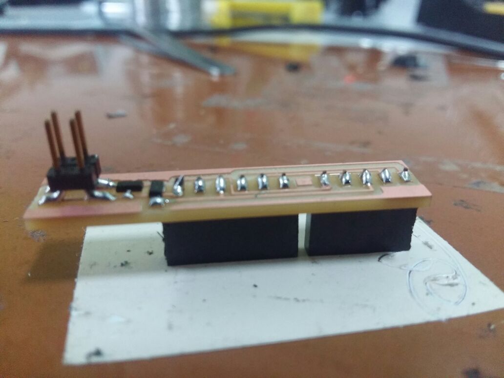
Final board after millling and soldering.
Programming
Next is programing.

chose 2 boards which i have already designed and milled for previous weeks, 1.INPUT+OUTPUT porad 2.Hello ftdi board,started using basic programming.
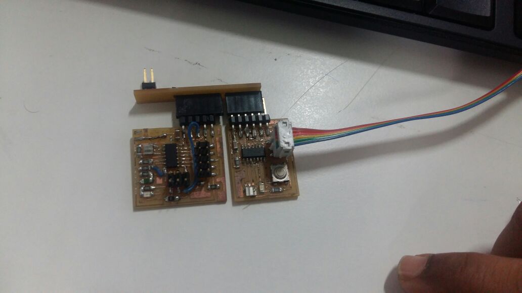
Final setup to program.
Testing of my board
First i have to test whether my interlink board is working when i connect it to Node and bridge.for that first i tried my test code.
Transmitter program
#include <SoftwareSerial.h>
SoftwareSerial mySerial(0,1);

void setup() {
  // initialize
  mySerial.begin(9600);
}

void loop() {
  mySerial.print('0');
  delay(100);
  mySerial.print('1');
  delay(100);
}
Reciever program
#include <SoftwareSerial.h>
SoftwareSerial mySerial(0,1);

const int ledPin = 6 ;      // the number of the LED pin

char data;

void setup() {
  // initialize
  pinMode(ledPin, OUTPUT);
  mySerial.begin(9600);
}

void loop() {
  data = mySerial.read();

  if (data == '1') {
    digitalWrite(ledPin, HIGH);
    }
    else {
 digitalWrite(ledPin, LOW);
  }
  delay(100);
}
I am soo happy by interlink board is working in a good way.
Next iam going to test my interlink board by applying the following condition
Condition :-Button press Led blink
Transmitter program
#include <SoftwareSerial.h>
SoftwareSerial mySerial(0,1);

const int buttonPin = 6;
int buttonState = 0;

void setup() {
  mySerial.begin(9600);
  // initialize the pushbutton pin as an input:
  pinMode(buttonPin, INPUT);
  digitalWrite(buttonPin,HIGH);
}


void loop() {

  buttonState = digitalRead(buttonPin);
  if (buttonState == LOW) {
    mySerial.print('0');
    delay(100),
    mySerial.print('1');
    delay(100);

    }
}
Reciever program
#include <SoftwareSerial.h>
SoftwareSerial mySerial(0,1);

char data;
<img src="img/w15/5.jpeg" width="600"/>
<img src="img/w15/5.jpeg" width="600"/>
const int ledPin =  4;


void setup() {
  mySerial.begin(9600);
  pinMode(ledPin, OUTPUT);

}


void loop() {

 data = mySerial.read();

  if (data == '1') {
    digitalWrite(ledPin, HIGH);
    // Debug if the data check works
    mySerial.print("ok");
} else {
 digitalWrite(ledPin, LOW);
  }
  delay(100);
}Files
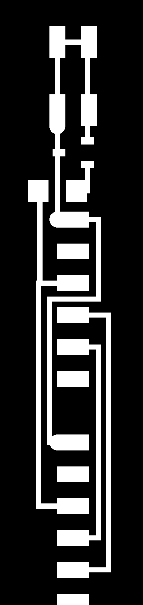
- Interlink board .CAD
- Traces
- Interior
- Holes
Test programs 1.Sender program 2.Reciever program
Final programs 1.Sender program 2.Reciever program
Assignment
Experiment 2
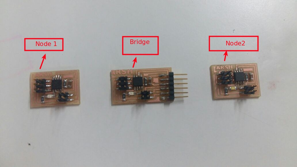
wired network connecting at least two processors. here iam going to communicate multiple boards using rx ,tx.My hello ftdi board as bridge(made on week 5), Input+output devices board(slave 1) as node 1,Neil's 2 boards as node 2 (slave2)and node 3(slave3). First programmed the bridge using fab isp,i didnt had to mill new board as iam using previous week's board.Node 1 is my input output board,Downloaded Nile's board then edited ,milled and stuffed it and used as node 2 and node 3

Programming Master board
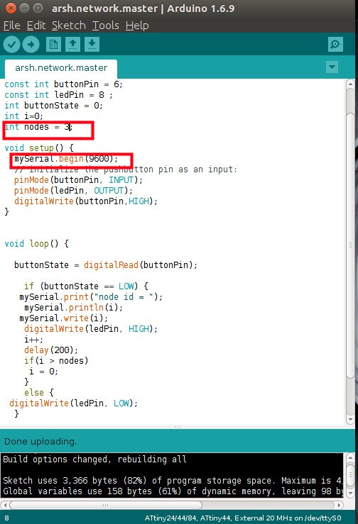
Master program explanation:-Intially declared i=0,when button press i value will write to serial (9600),that means communication happening, then next step is i value will get incremented to i+1,then did set a delay ,then did put a condition,if i>nodes(i have alreday gave nodes =3,here iam using 3 nodes)then i =0 ,that means no nodes get detected,else led will blink when press the button.
Slave program explanation:-it will always check serial availability inside the loop,when it awailable it will read to a charector 'data' ,then if readed data is equal to its identiy or node id then led will blink.
Node 1 Programming.

Node 2 Programming

Node 3 programming.
Node 2 and node 3 board's microcontroller is Attiny 45,so declared pin 3 and pin4 as rx and tx respectively,then declared pin 0 as output pin,here connected led between vcc and pin0,so when state is low ,circuit will close and LED will blink.
Master program
#include <SoftwareSerial.h>
SoftwareSerial mySerial(0,1);

const int buttonPin = 6;
const int ledPin = 8 ;
int buttonState = 0;
int i=0;
int nodes = 3;

void setup() {
  mySerial.begin(9600);
  // initialize the pushbutton pin as an input:
  pinMode(buttonPin, INPUT);
  pinMode(ledPin, OUTPUT);
  digitalWrite(buttonPin,HIGH);
}


void loop() {

  buttonState = digitalRead(buttonPin);

    if (buttonState == LOW) {
   mySerial.print("node id = ");
    mySerial.println(i);
   mySerial.write(i);
    digitalWrite(ledPin, HIGH);
    i++;
    delay(200);
    if(i > nodes)
     i = 0;
    }
    else {
 digitalWrite(ledPin, LOW);
  }


}
slave program
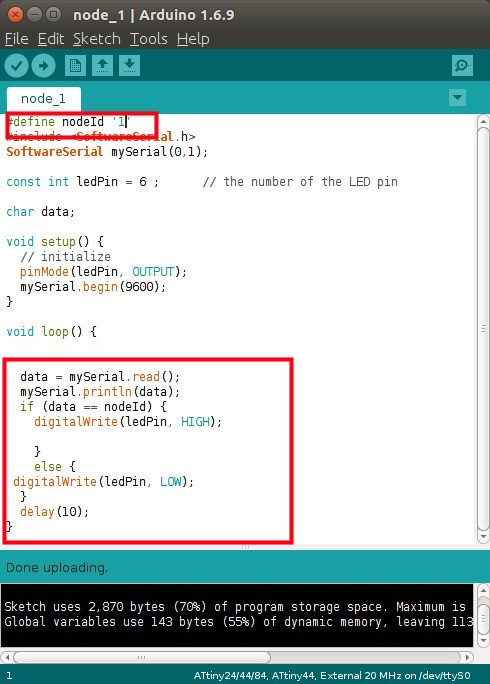
#define nodeId '1'
#include <SoftwareSerial.h>
SoftwareSerial mySerial(0,1);

const int ledPin = 6 ;      // the number of the LED pin

char data;

void setup() {
  // initialize
  pinMode(ledPin, OUTPUT);
  mySerial.begin(9600);
}

void loop() {
data = mySerial.read();
mySerial.println(data);
  if (data == nodeId) {
    digitalWrite(ledPin, HIGH);
    }
    else {
    digitalWrite(ledPin, LOW);
    }
delay(10);
}
Files
Experiment 3:
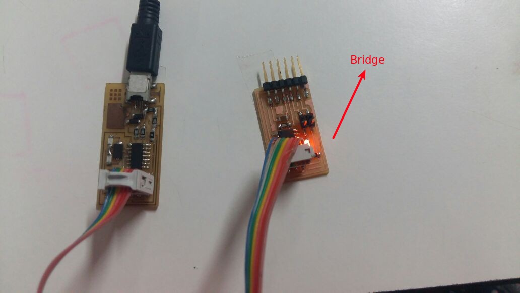
Here iam using Neil's serail communication examples,Uses Attiny 45 chip.Downloaded Nile's board then edited ,milled and stuffed it.Here i am using 2 nodes and 1 bridge to communicate.
Programming the boards
Modifiying the C code:
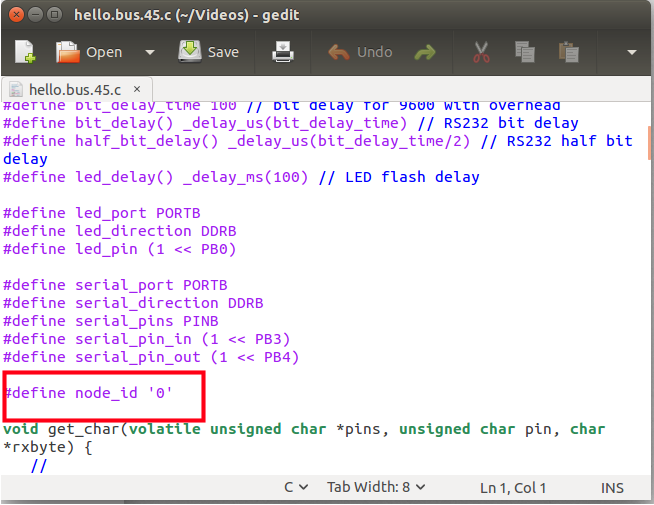
- For eaach node in my metwork i modified the Hello.bus.45.c code .
- Now each node has differnt node Id number (0,1,2)
- After editing sved the file ,connected the bridge board to computer using FTDI Cable and used Fab isp to program.
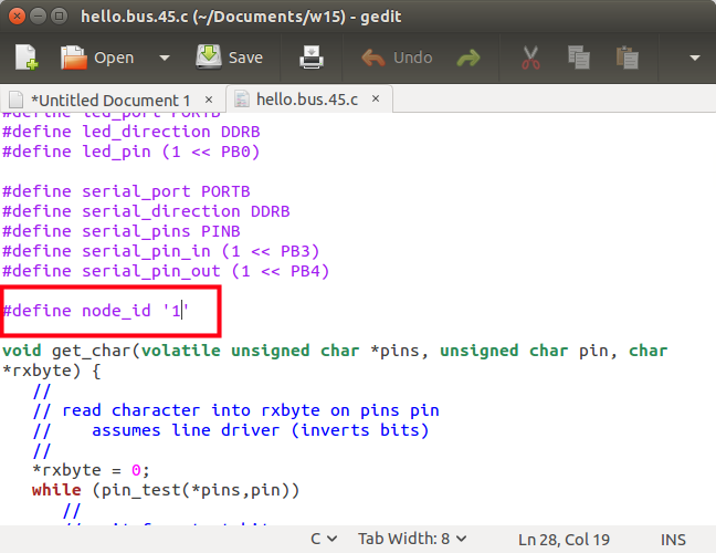
First programmed bridge,used Fab isp which i made on electronics production week,to program downloaded Niel's programs "hello.bus.45.c" and "makefile" ,for programming the bridge i modified the C code file as "node _id is '0' .
sudo make -f hello.bus.45make 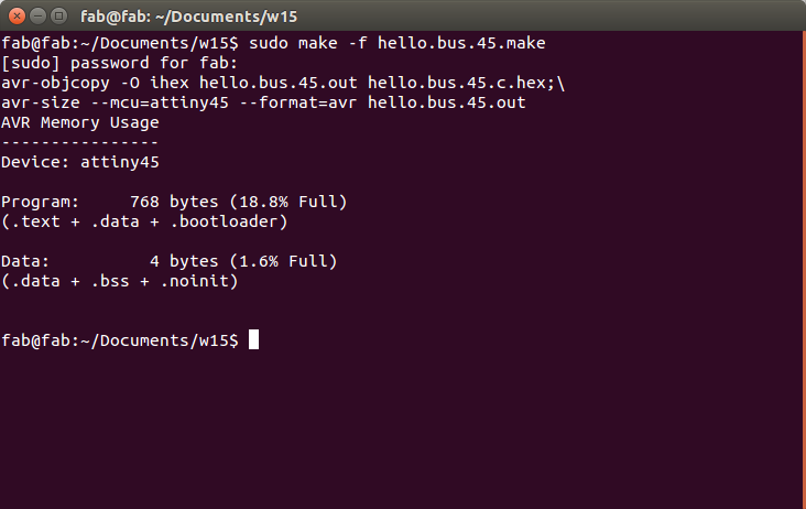
sudo make -f hello.bus.45make program-usbtiny 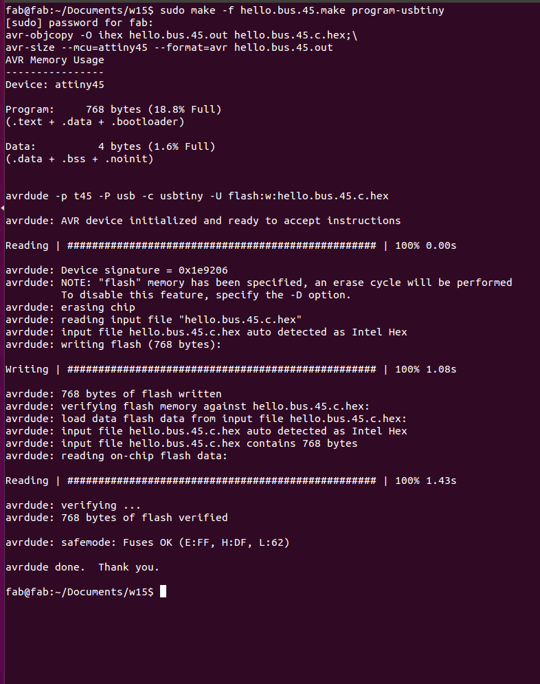
Each of the nodes (including the bridge) could be identified as a unique "character" on the network and communications (as mentioned earlier). So, starting with identifying the bridge as "0", in turn we identify node "1" and then, furthest away, node "2".
To program Node 1

To program Node 2

Repeated same procedure of Node 1 Programming after editing Node id 2.Next stage is to use the serial monitor in Aurduno to communicate with the network.
After programming bridge and nodes seperately with 3 different node numbers ,plugged using FTDI cable the bridge in to computer with nodes attached using cable to connect Nodes and bridge.Used Niel's python program to controll the nodes,
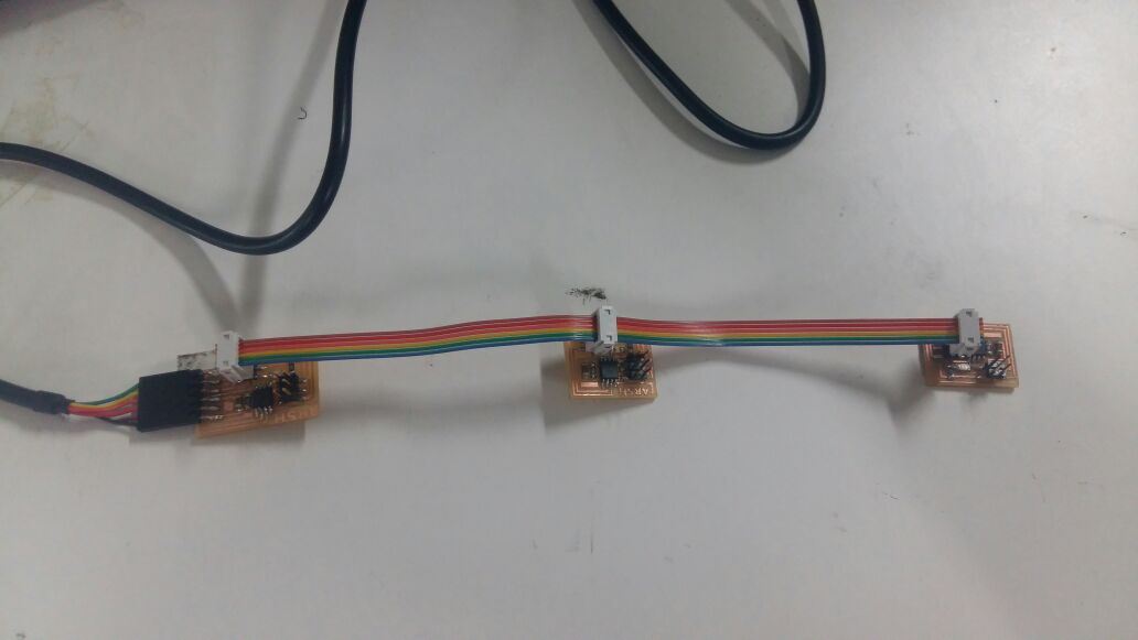
Downloaded niel's python program to controll the bridge and node then used following command.
sudo python term.py /dev/ttyUSB0 9600When character "0" was pressed in the serial monitor, the led would flash on the bridge (named "0"). When character "1" was pressed, the led would flash on node "1", etc,this is what i expected,but when i press 0 i can see all led are blinking.