Week-19
Project development
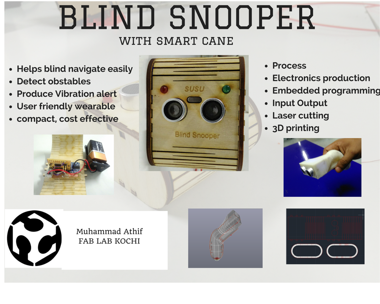
Final Project Development
For my final project,
For this assignment should be mentioned that changes to the original idea of an artificial system for beehives were made, this because the time to determine whether any implementation would affect bees and avoid damaging your space is very long, about one year.
For this assignment, I decide a device for the problem that we are trying to tackle is being able to Navigate the blind people. Instead of the blind stick and this module will interact , what if we could enable them to move around and interact with the environment. The blind will independent in his on the world...
The blind snooper of this idea is to eventually have it. Why because nowadays they seeking help from others. Imagine unpacking a backpack full of these robot modules, and assembling them to perform some task like distributing food through a line faster. Or sorting specific medical supplies to go to one area. Maybe even something as crazy as being able to dig out areas for standing water to flow away from temporary shelter locations.
Throughout this paper the research, development, analysis, design and implementation of an automotive safety system that allows users to detect objects and vibrate accordingly.
The system is completely self-contained, uses ultrasonic sensors to sensing an object in front of the stick and front chest send a signal to the central module so that it, in turn, send a vibrational alert the user. The user to be notified that any object obstructs the travel from him and change the direction of himself for navigation
What is the Deadline? How much time do you have left?
I have another two weeks left to complete the project. I have almost completed all the processes associated with the project. After a quick test run, I have dismantled the parts Blind snooper to get it perfectly working in the second attempt. I will be utilising the remaining time for that.
What tasks have been completed, what tasks remain?
Most of the tasks have been completed. I had made the PCB boards, 3D design planned on the arrangements.But the 3D design needs to improve more . the programming finished almost during the input and output week. I branding part using vinyl sticker needs to be done. I added two LEDs, the vibration motor does not get from the shop. I also need to figure out a quick way to fix that.
How will you complete the remaining tasks in time?
As I am spending most of my working hours of a week in Fablab, It would be easy to complete the remaining tasks with the in the available time. I am taking photographs of the progress and noting down the points.
What has worked?
Almost all the tasks relating the physical outlook and the design of this particular project have worked out fine This includes.
Laser cutting of outer kerf with a trotec laser cutter. 3D printing of handle on Dimension 1200ss printer Milling and stuffing of board on Roland Modella Designing of all the parts, boards etc of design software. Vinyl cutting of branding sticker on the device.
What hasn't worked?
I had some trouble getting the Vibrating motor, using the custom board I made but I am easily able to do the same with an Arduino board. Having said that, If it works fine on Arduino, It should also work fine on the board I made in Kokopelli, I am hoping to pull this off within the available time.
What questions still need to be resolved?
A lot of questions are there, in fact, I ended up with more question than when I begin the project. The main questions are.
- how the frequency changing vibration accordingly distance.?
- have any other transducers other than vibrating motor?
- What's the best capacitor need to 9V DC battery board?
- how the internal design the snooper?
- how it make simple?
What have you learned?
I have learned a lot, for example, I have used the following techniques for my project.
- Kokopelli
- Machine design
- Moulding and casting
- 3D/2D designing
- 3D printing
- Electronics production, design and embedded programming
I have also learned a few important things, about time management, I realised that I shouldn't have chosen such a complicated project if I had only just an over a month of time. I complete underestimated the complexity.
Development Milestones
Preliminary Sketches
As my final project, i am planning to make a device to help the blind person ,to help them navigate freely.According to my planning and my idea these device has two units.
Unit 1- A handheld device (it detects and alert the person about obstacle within 1-meter range in inclined path with respect to cane by producing vibration when they navigate)
Unit 2- A portable wearable device which can hook in dress,or wear using a chain or can take in chest pocket(it detects and alert the person about obstacle within 1-meter range in horizontal direction with respect to navigation path by producing vibration)

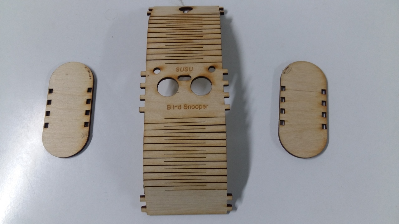
Here is rough plan of my project ### Mechanical #### Designing of 2D case Planning to use plywood as raw material,so the design should be something which can make using plywood(laser cut),for that decided to design using Autocad , To get flexible shape used command 'line' so that using laser cutting process I can make a kerf figure.To make this kerf perfect profile I had to make ready side support ,for that designed slit on the side.this entire model is a press fit,saved it as DXF File.

Designing of 3D Model
Before 3d modelling, I had to think what should I design. I need an Ergonomic shaped device so that I can fix it with a cane, the device should be able to contain 3 components of my project-Battery, vibrating motor,ultrasonic sensor. Front portion dimension is same as that of the ultrasonic sensor because this module should be perfectly fit to include all the above components.
- 1 st stage of designing :-Designing software-Autodesk Inventor
Operation-Multiple planes
   -Lofting
   -Extruding
Save the file in DWG formate the exported it to STL Formate .
- 2 nd stage of designing :-Designing software-AutCAD
Opened the 1st design file for further editing,what I need is exactly a press fit like structure ,it should be able to use without screw,to make that structure did slice the entire object design in middle to two perfect half,then using union,extrude and subtract commands to make male taps on one portion and subtractive female tap on next portion.

Designed from Autodesk inventor
Part -Female
Part -Male
Laser Cutting
In this process first, off did laser cut off my desired model,engraved my product name "SUSU" using INkskape software , a total time duration for this process was about 11 minutes,got the project case as I wished.
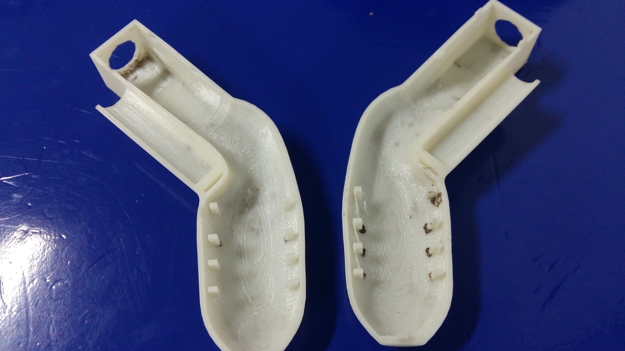
3D printing
2 nd module of my project is 3d printed ,Handheld device.3d printed the handheld device by two steps,it using Dimension SST 1200 ES ,it took almost 6 hours to complete printing,to dissolve the supporting material I took almost 8 hours.
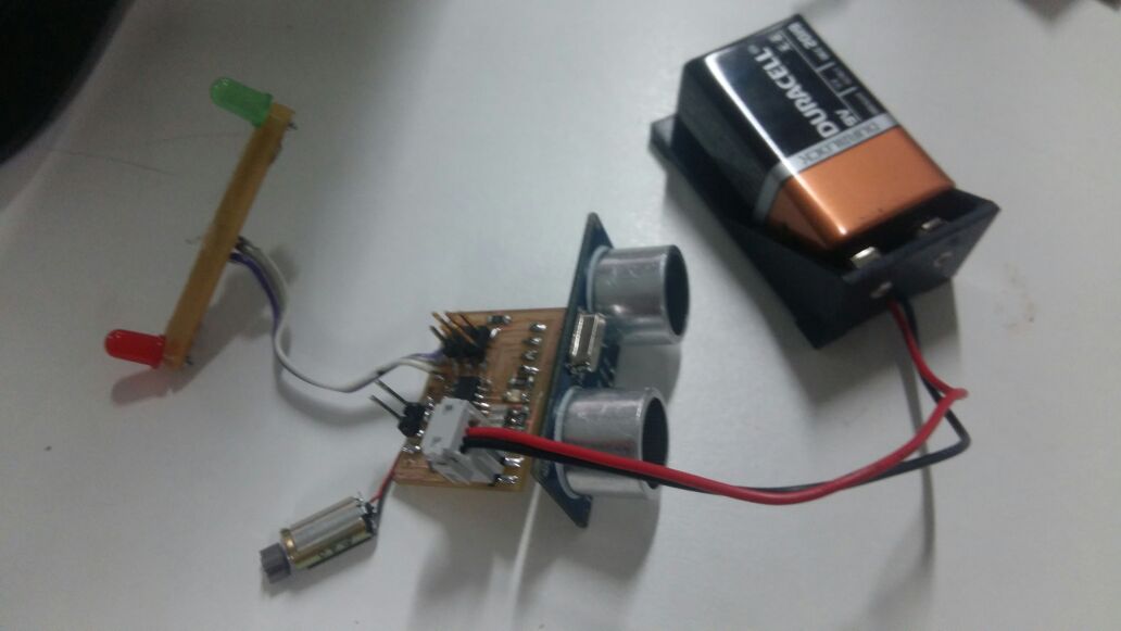
Electronics
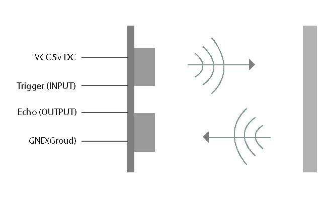
The main part of this project is a sensor (ultrasonic sensor),this sensor will produce ultrasonic sound when power gets and this sound will reflect back when it hits an obstacle,this returning sound velocity is measuring and converted into distance.This works on a basis of Doppler effect.
Blind snooper controller (sensors and Vibrator)

this picture shows exact explanation how this device work,speed of ultrasonic sound is 34 m/s this speed will convert to cm/s ,and time is equal to speed divided by velocity,we have to find a constant so that I can find unknown distance by multiply this constant with velocity which is producing by ultrasonic sensor.

Ultrsonic sensor has 4 pins.vcc,trigger,echo,gnd,among these four pins Trigger pin transmits,so it is input and echo pin recieves.
Vibrating motor this is a dc motor,at the end of the shaft, there is an eccentric load when this motor rotates an eccentricity produces and this will convert into vibration. Frequency setting on-off mechanism,to make frequency variation here using the on-off mechanism,this is the hard task in this project,that's what I feel.

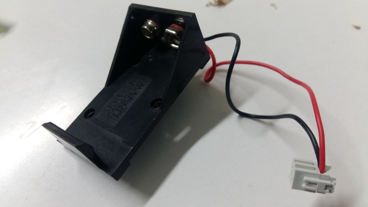
9v square battery and its holder.
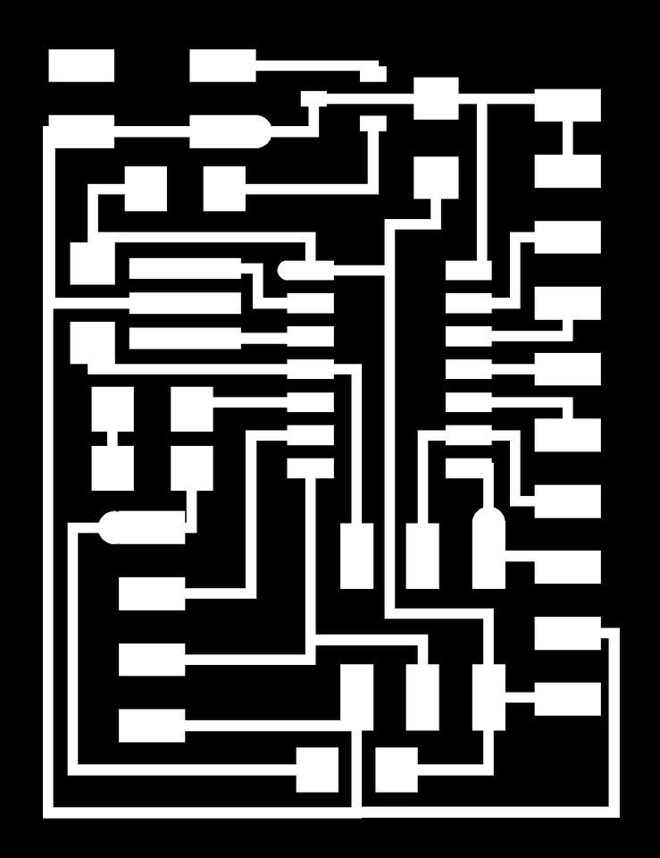
PCB Design, Milling and Soldering
PCB Designing step is the easiest step for me because I like Kokopelli soo much because I feel it is so much easier than Eagle,I will be thankful to Master for this great gift.
components:-
Attiny 44, LED crystal, resistors, power 2x2 pin, voltage regulator, capacitors, isp pin, HCSR04 4 pin.
I added a pin class 4x1,and also a 10x1 on Kokopelli.Then I added a diode to avoid the backwards flow of current through the voltage regulator.I have used ATtiny 44 as a micro controller, I need to use all pins for future plans, so I connected all pins to the pads.

smart.cane.44.cad, smart.cane.44.png, smart.cane.44.traces.png, smart.cane.44.interior.png, smart.cane.44.holes.png
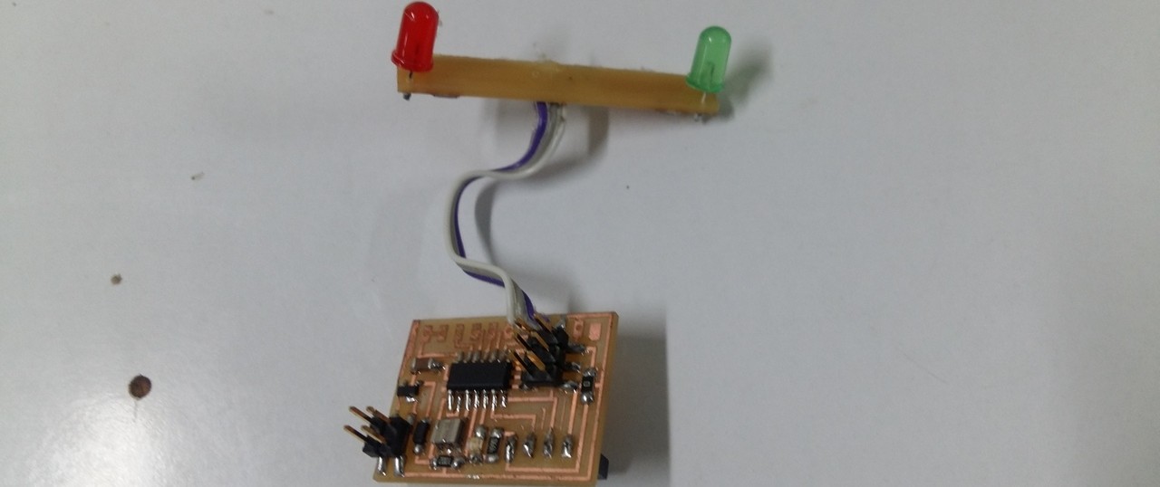
I need to blink two LEDs, red and green.In such way that when the object comes nearer to the device red led blinks and when the object is away from it the green led blinks.So I made another led board using Kokopelli.

smart.cane.led.cad, smart.cane.led.png, smart.cane.led.traces.png, smart.cane.led.interior.png, smart.cane.led.holes.png
After finishing the design I milled both boards using model,it looks fine,traces are clear when I compared with my board design,next step is soldering,did solder all components within 1 hour. after soldering, I did inspect my board using a digital microscope,when I feel that is correct next I learnt to program.
Programming
Tasks:
- Distance measuring
- Vibration frequency setting
- Led blinking
I have already done some work in a previous week(Input week)for the final project,distance measuring program,measured distance and displayed it on the serial monitor,so the first task is over. Next, is the second task that is vibration frequency setting,according to distance measured in the first task,here I am considering distance loop 1 meter
API(Arduino Programming)
int trigPin = 7;    //Trig - green Jumper
int echoPin = 6;    //Echo - yellow Jumper
int duration, cm, inches;

void setup() {
  //Serial Port begin
 // mySerial.begin (9600);
  //Define inputs and outputs
  pinMode(trigPin, OUTPUT);
  pinMode(echoPin, INPUT);
  pinMode(5, OUTPUT);
  pinMode(4, OUTPUT);
  pinMode(8, OUTPUT);

}

void loop()
{
    digitalWrite(8, HIGH);
    delay(25);
    digitalWrite(8, LOW);
    delay(100);

  // The sensor is triggered by a HIGH pulse of 10 or more microseconds.
  // Give a short LOW pulse beforehand to ensure a clean HIGH pulse:
  digitalWrite(trigPin, LOW);
  delayMicroseconds(5);
  digitalWrite(trigPin, HIGH);
  delayMicroseconds(10);
  digitalWrite(trigPin, LOW);

  // Read the signal from the sensor: a HIGH pulse whose
  // duration is the time (in microseconds) from the sending
  // of the ping to the reception of its echo off of an object.
  pinMode(echoPin, INPUT);
  duration = pulseIn(echoPin, HIGH);

  // convert the time into a distance
  cm = (duration/2) / 29.1;

  delay(250);


  if (cm<30)
  {
    digitalWrite(5, HIGH);
    delay(50);
    digitalWrite(5, LOW);
    delay(30);
    }
  else{
    digitalWrite(4, HIGH);
    delay(50);
    digitalWrite(4, LOW);
    delay(30);
  }
}
Assembling process
Blind Snooper Assembling:
Blind snooper is the total of 2 modules,first one is chest device and the second one is handheld device.these 2 main electronics components.

I did fit these 2 electronics part in kerf due which I did laser cut as per I designed.
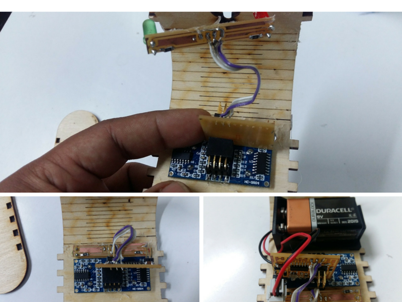

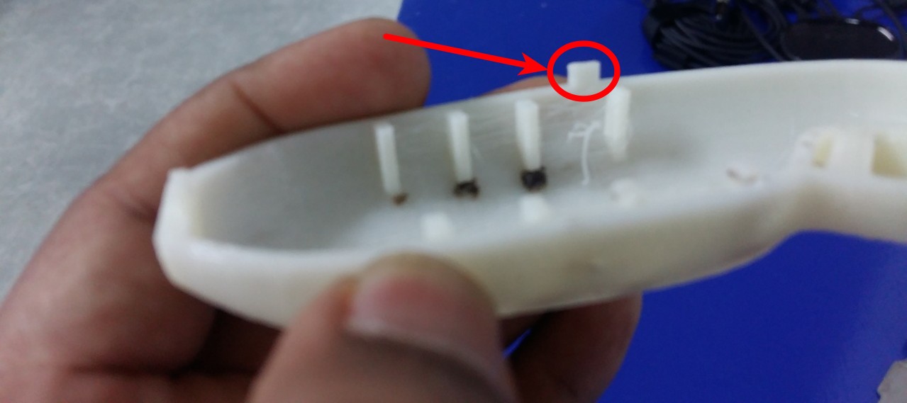
next was to set the board designed to work these electronics components,plus battery and battery holder.did paste the vibrating module on the side part. ### Smart Cane Assembly: Assembled separately printed portions of handheld module-Male and female parts by combining male tap and female tap.

Male tap made additvely,you can see it very clearly .
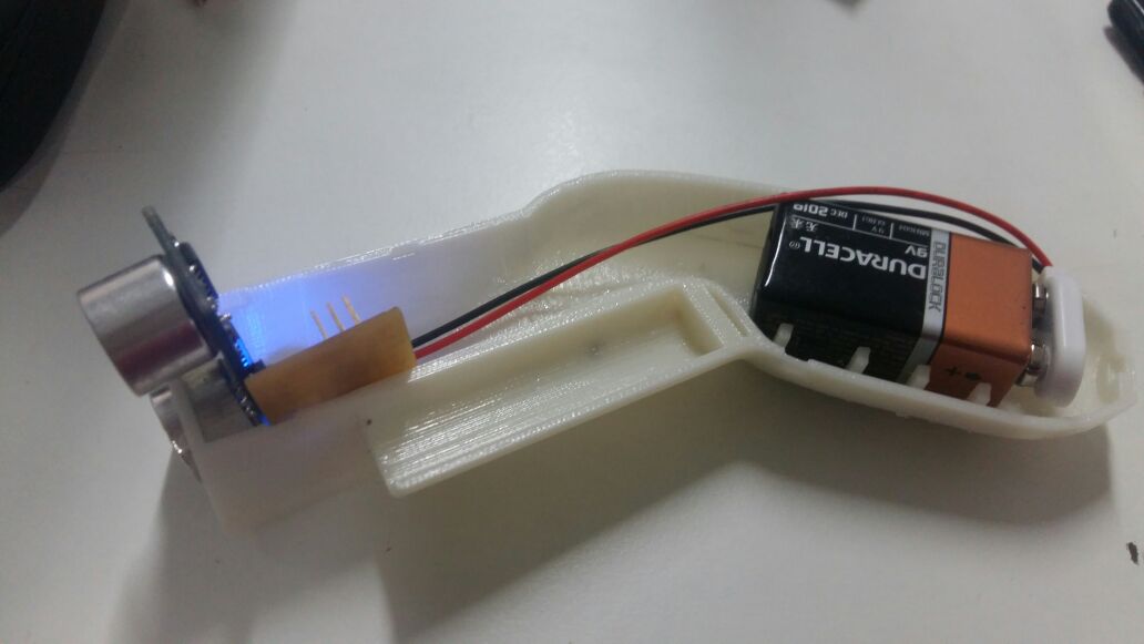
This is the half portion of handheld module which shows how the electronics parts have setted inside in it.
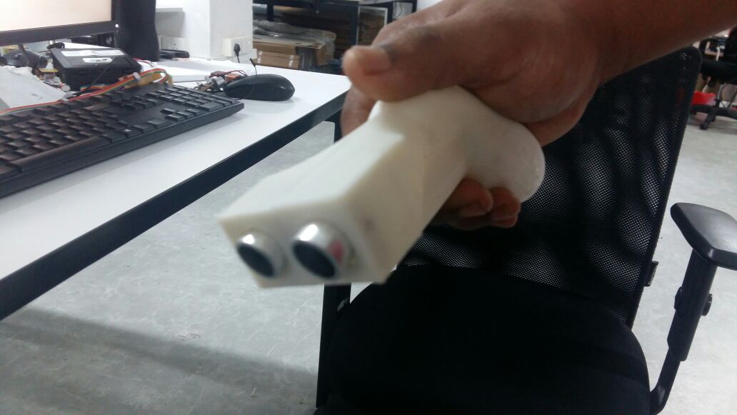
Final assembled handheld module.
Project Slide
Project Vedio
Files
Smart Cane PCB board
LED board
Laser Cutting
3D Printing
atif handle.dwg, atif handle.stl, atif handle-1.stl, atif handle.dwg