Week 15 : Networking and communications (May 11)
Assignment :
Design and build a wired or wireless network connecting at least two processors.
Rx Tx Communication
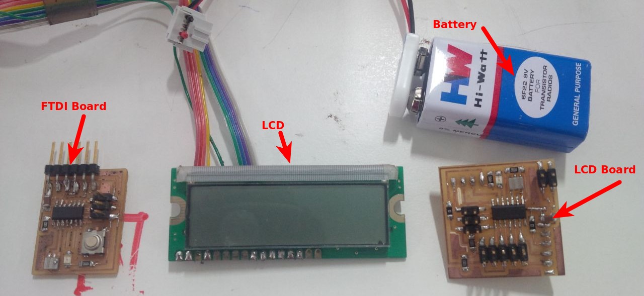
This week i would like to do transmission reciever communication between my LCD board and FTDI board.
Here iam planning to do when i press the button in FTDI Board ,the message which i would like to display should be appear in LCD Display.
Programming step
First i did compile the program and did upload to FTDI Board using Arduino.
#include <SoftwareSerial.h>
SoftwareSerial mySerial(0,1);

const int buttonPin = 6;
int buttonState = 0;

void setup() {
  mySerial.begin(9600);
  // initialize the pushbutton pin as an input:
  pinMode(buttonPin, INPUT);
  digitalWrite(buttonPin,HIGH);
}


void loop() {

  buttonState = digitalRead(buttonPin);
  if (buttonState == LOW) {
    mySerial.print('0');
    delay(100),
    mySerial.print('1');
    delay(100);

    }
}
next was about clone program,did compile the program first, Rx and Tx pins defined as 7th pin and 6th pin respectively.My aim is when i press button message should get printed,when button is off message shoud disappear,for that i did apply "if loop condition",so when condition satifies the message will print,in other case i did set another condition as print space 16 times,this how i did code.
#include <SoftwareSerial.h>
SoftwareSerial mySerial(7,6);

#include <LiquidCrystal.h>
LiquidCrystal LCD(5,4,3,2,1,0);

const int ledPin = 8 ;

char data;

void setup() {
  // initialize
  LCD.begin(16,2);
  LCD.setCursor(0,0);
  LCD.print("Welcome to ooty");

  pinMode(ledPin, OUTPUT);
  mySerial.begin(9600);
}

void loop() {
  data = mySerial.read();

  if (data == '1') {
    digitalWrite(ledPin, HIGH);
    LCD.setCursor(0,1);
    LCD.print("Nice to meet you");
   }
    else {
 digitalWrite(ledPin, LOW);
 LCD.setCursor(0,1);
 LCD.print("                ");


  }
  delay(100);
}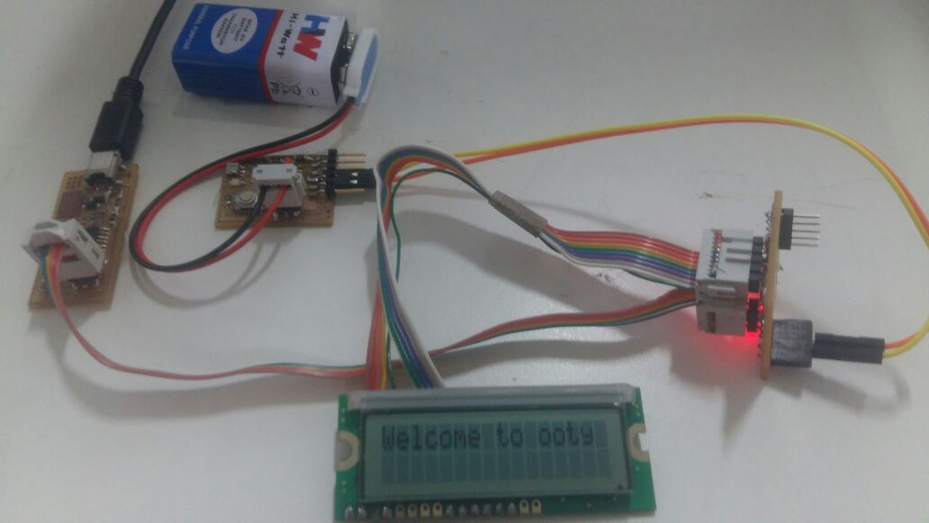
Final testing of my code
Files
Asynchronus
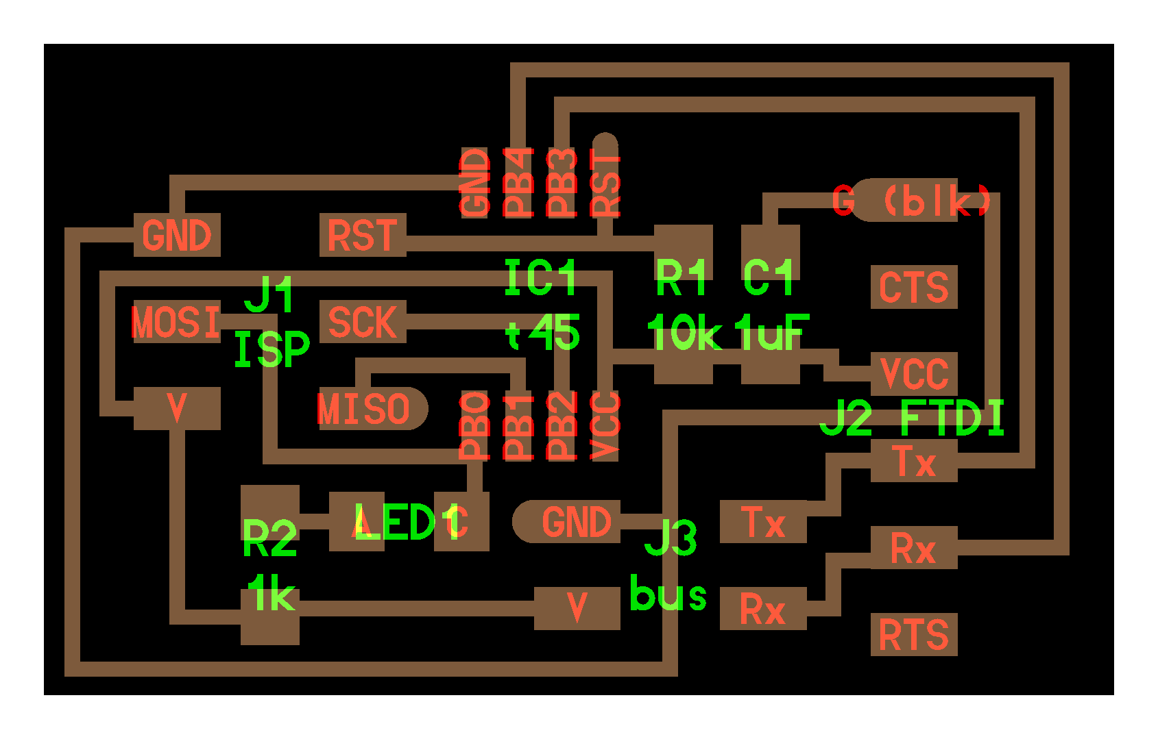
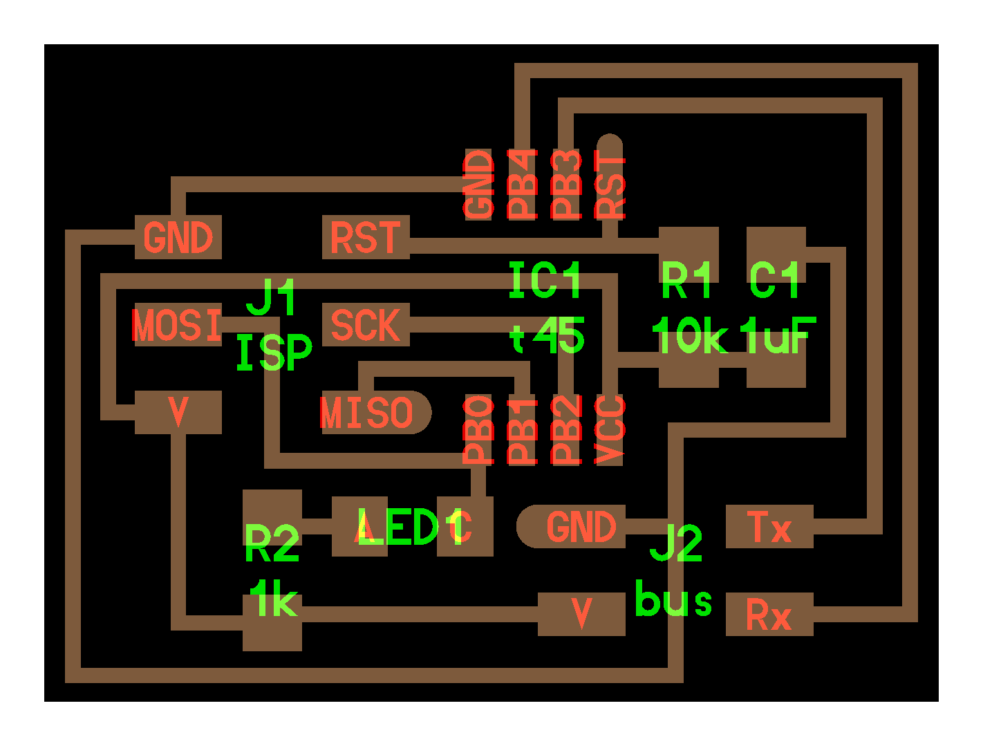
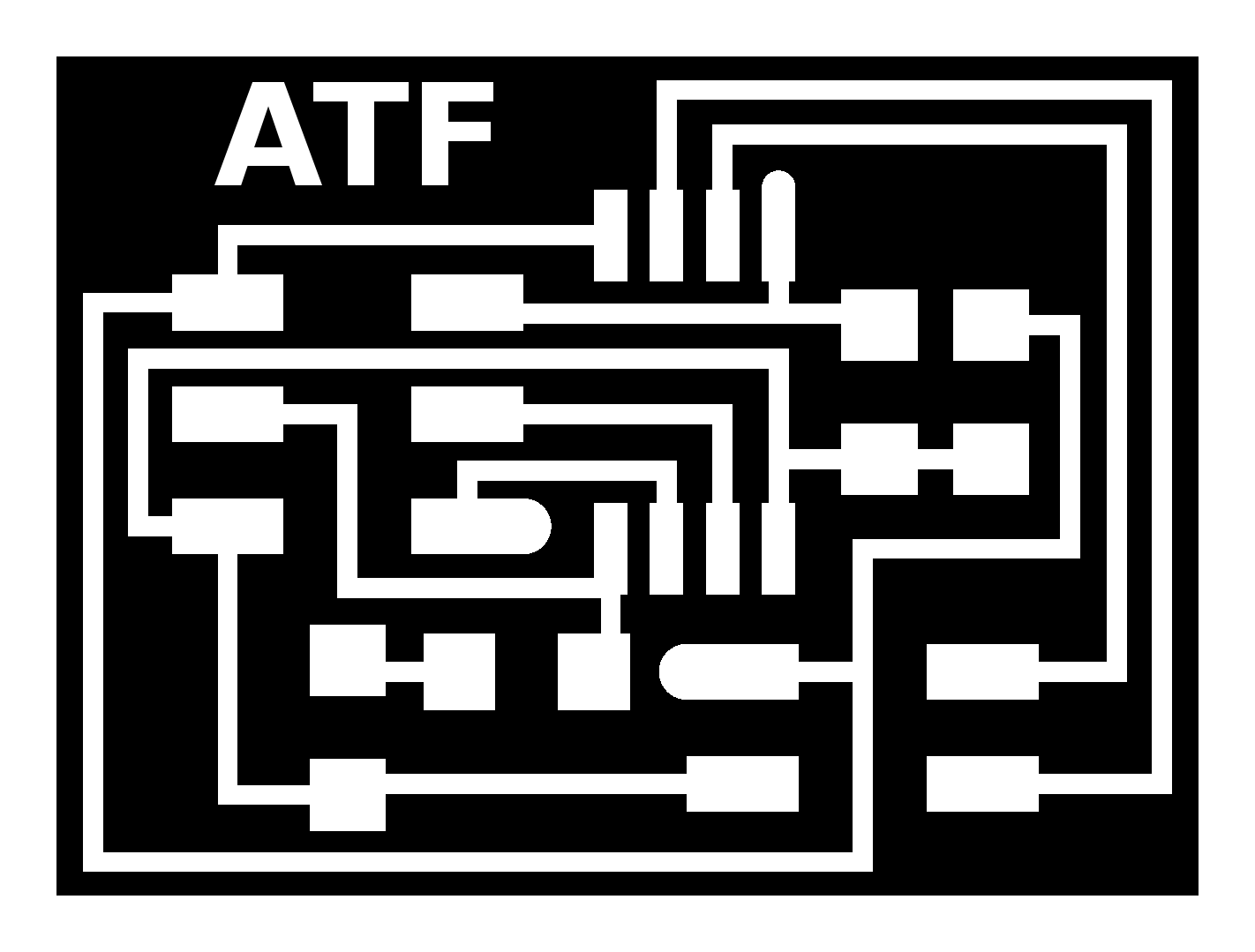
After all these work,to get more familiar with the concepts of networking I used Neil’s serial Communication examples. This uses attity 45 chip. I use the pins connected to isp as the trasmitter(tx) and receiver(rx) pins too, so that I can use the ISP pins for communications between the boards. SCK and MISo are used as as tx and rx. I wanted to add resonator but couldnt.
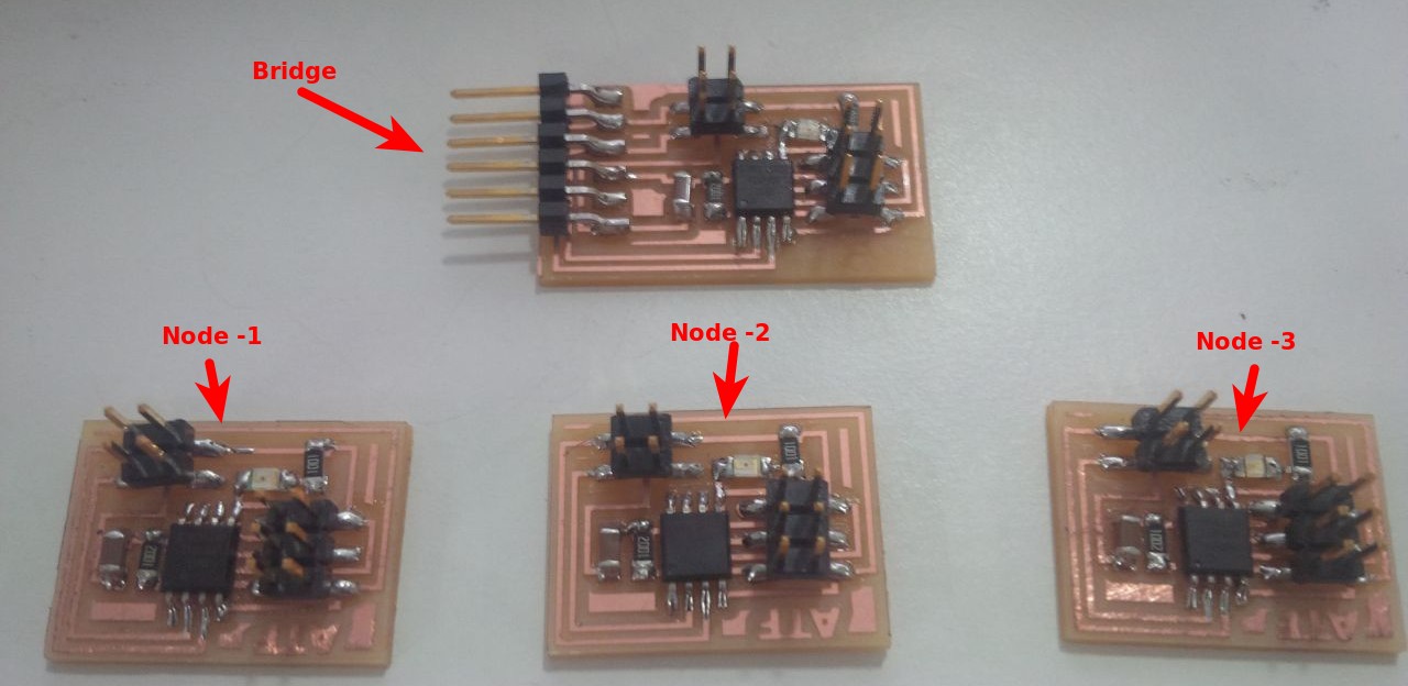
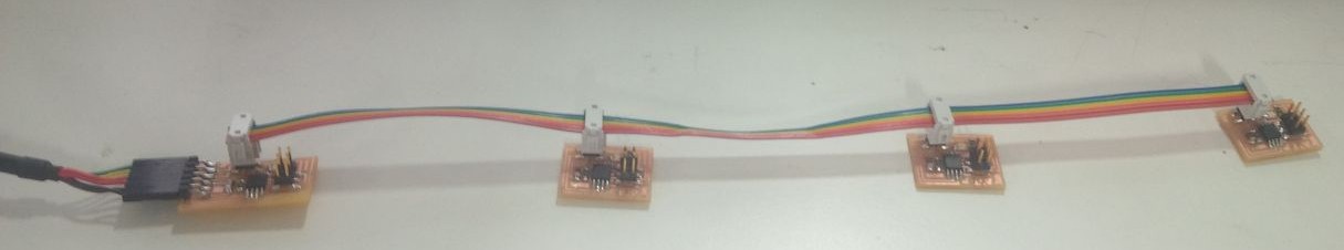
There are two board here, the bridge and the node. The bridge connects the computer to the network of microcontrollers through ftdi cable. The node is connected to the bridge through ISP cable. It shares many pins but tx and rx are important. I created one of each.
I uploaded the program with node id hardcoded to identify wach board.
For bridge
#define node_id '0'For nodes
#define node_id '1'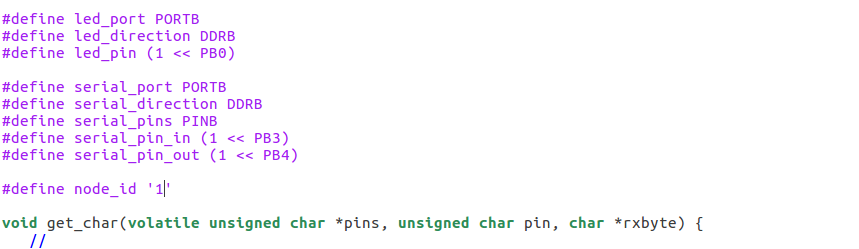
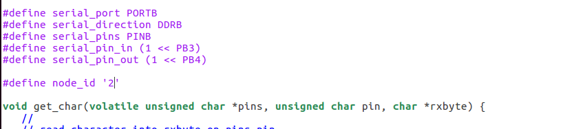
On sending a either 0 or 1 from the serial FTDI the bridge or the node react to it and output message identifying themselves by their node id.
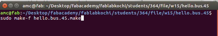
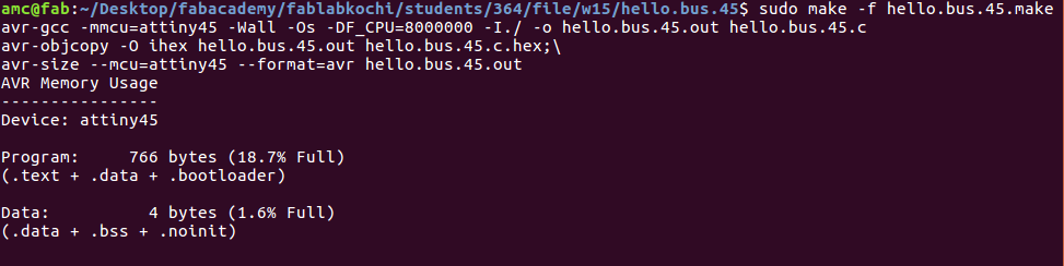
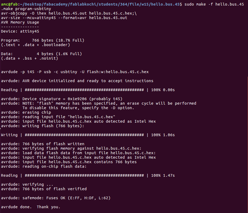
Then I make the make file:
sudo make -f hello.bus.45make
sudo make -f hello.bus.45make program-usbtiny
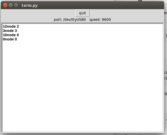
Here the Neil's python program for controll the node. use this code
sudo python trym.py /dev/ttyUSB0 9600

The interface like this. but the output not exact. will check it and fix later.
Files
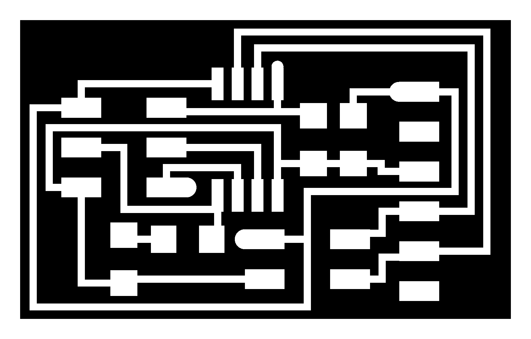
- atf.bus.45.bridge cad, Board, traces, interior
- atf.bus.45.node cad, Board, traces, interior
- make, c
- term.py
If you need to commumicate with multiple microcontrol its a good chioce to keep in Arduino program then as Master and slaves.
Master:
void loop() {
    update_ramps()
    for(int i=0; i< num_slaves; i++) {
        send_to_all(i, ramps[i]);
Slave 1:
const int id = 1;
int recived_id, recived_value;
void loop() {
    read_data();
    if(recived_id == id) {
        do_motor_step(recived_value);
    }
}
And serial communication in which RX/TX from the master is sent to all slaves.
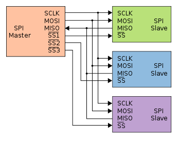
SPI
SPI also uses shared lines for data: a single MOSI, and the MISO lines connected. To address each slave individually you'll need one SS (Slave Select) line per slave. So that's at least 5 I/Os: MOSI, SCK, 3 ×× SS, and MISO if you also want to read data from the slaves. Each additional slave adds 1 I/O pin on the master.
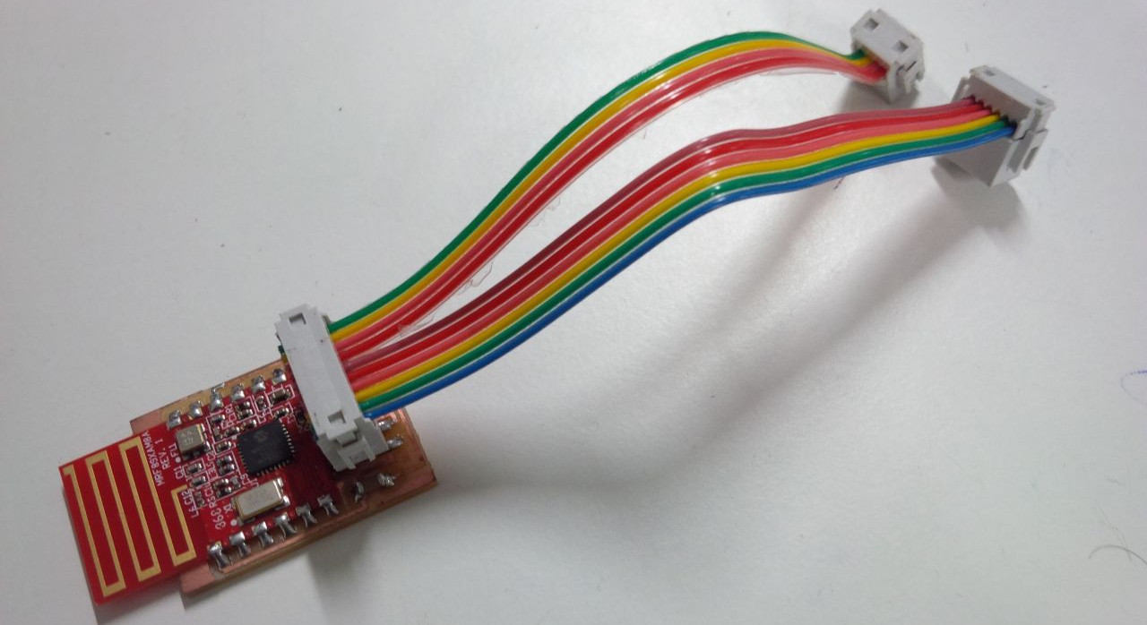
I used design a board using kokopeli which wireless data tranfer.After stuffing the board i did burn bootloader which got sucess,but during programming it did not work,Actually this board is for my project ,but i didi skip that plan due to lack of time.
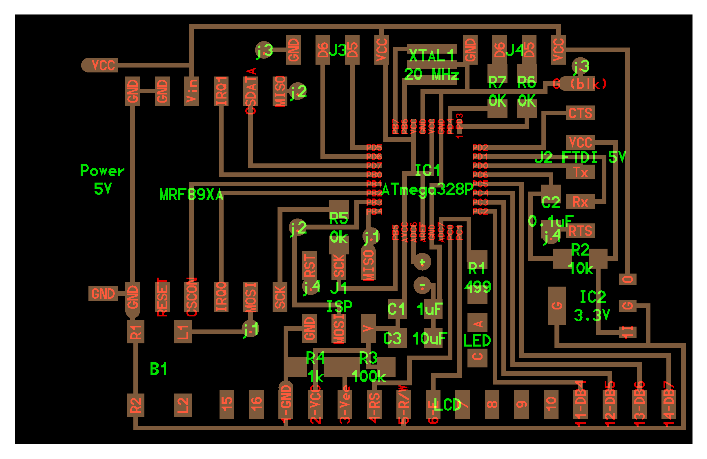
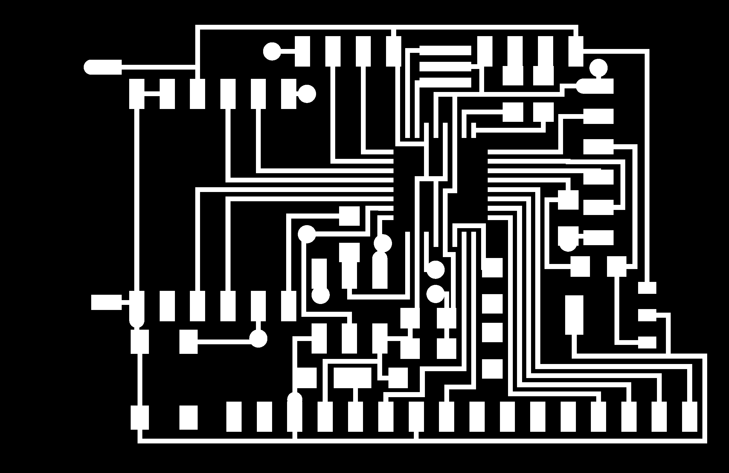
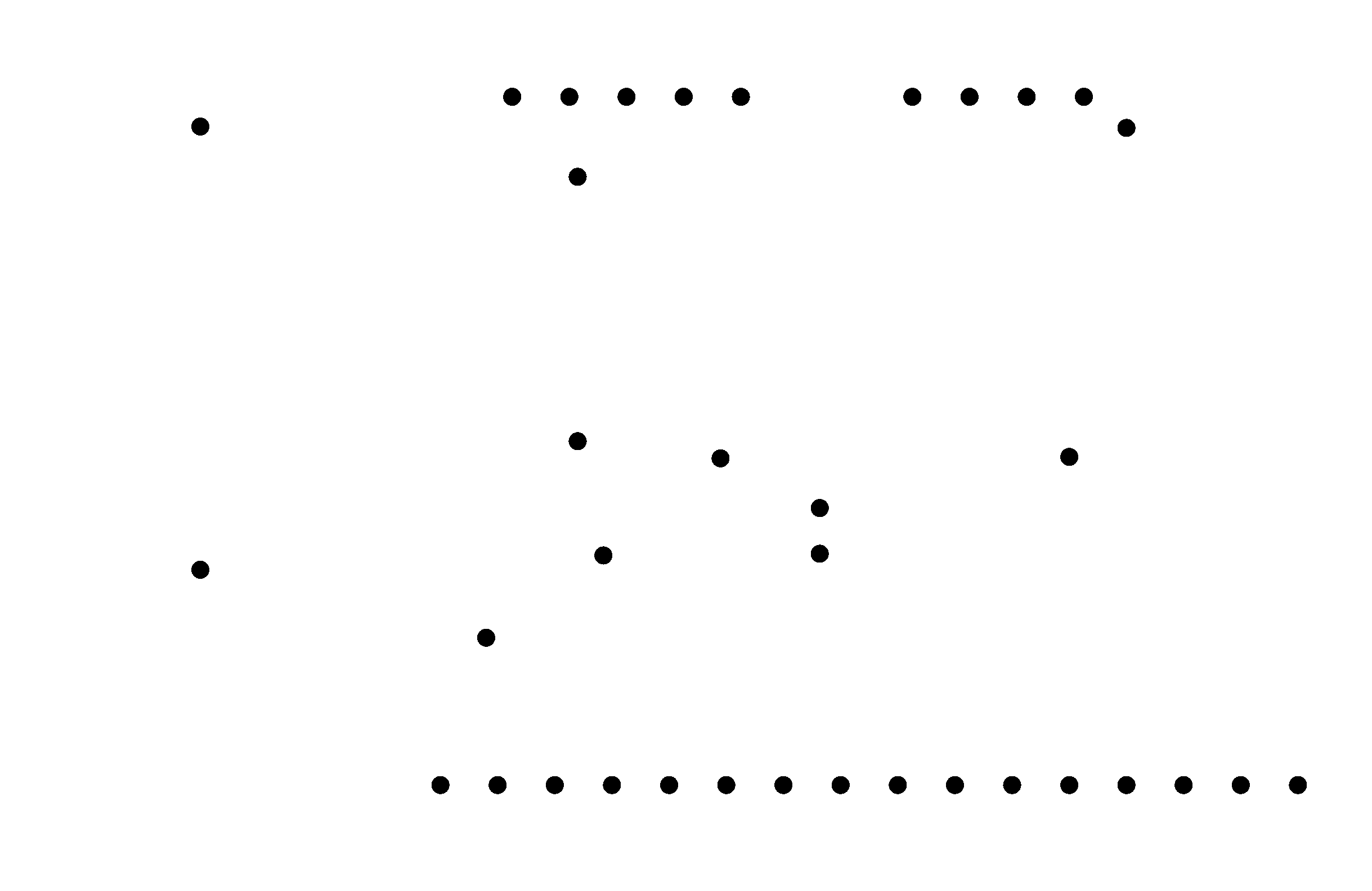
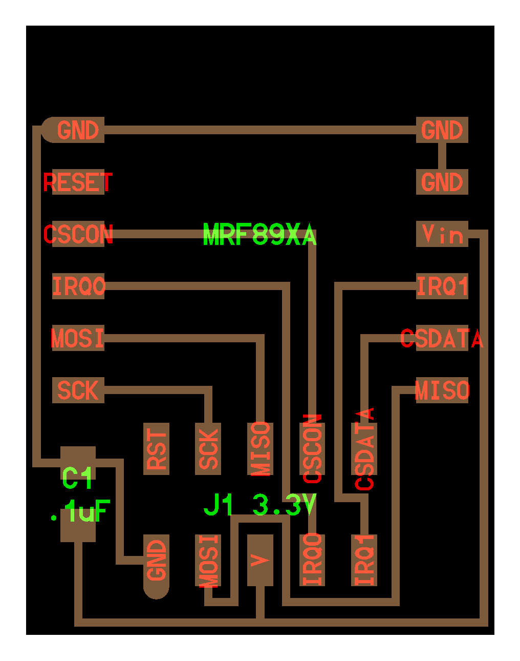
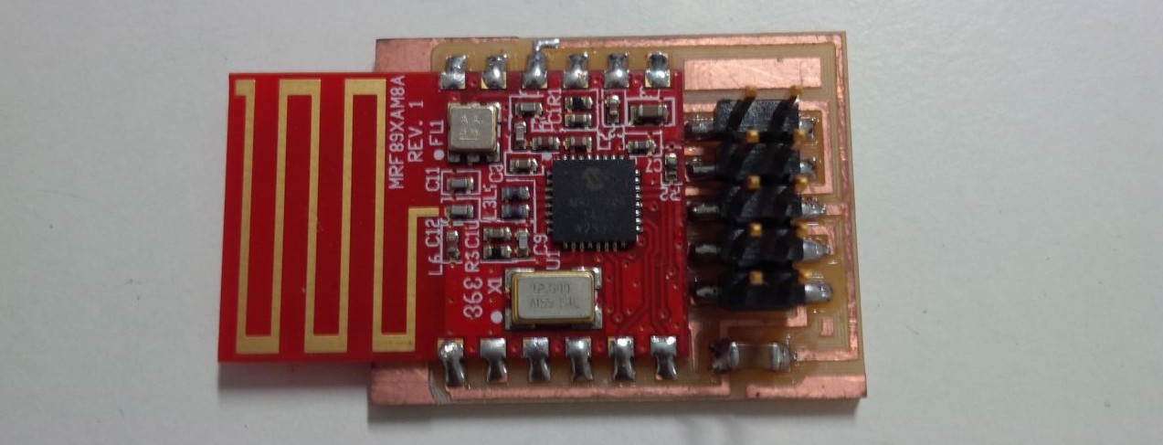
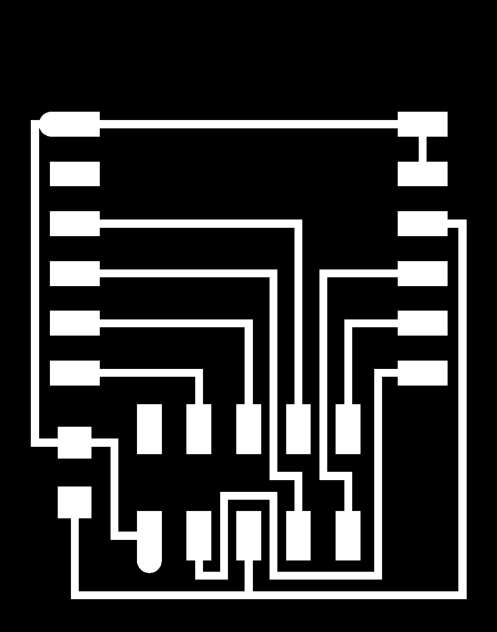
MRF89XA
I designed differnt board for MRF89XA using kokopelli. For placing in all micro control.