Week 11 : Input devices : Apr 13
Assignment :
This week's assignment is to measure something: add a sensor to a microcontroller board that you have designed and read it.
An input device provides information about a work environment such as magnetic fields, temperature, light, sound, acceleration, orientation, vibration and more ,this information is sensed by a device called sensor and then is processed and measured by a microcontroller.There are hello world example circuits to measure magnetic fields, temperature, light, sound, acceleration, orientation, vibration and more.
Distance sensor
Desgining PCB
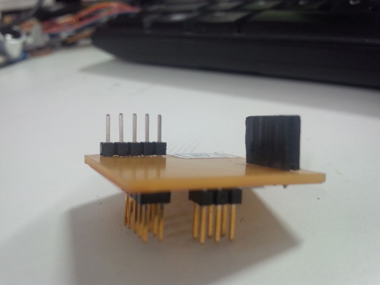
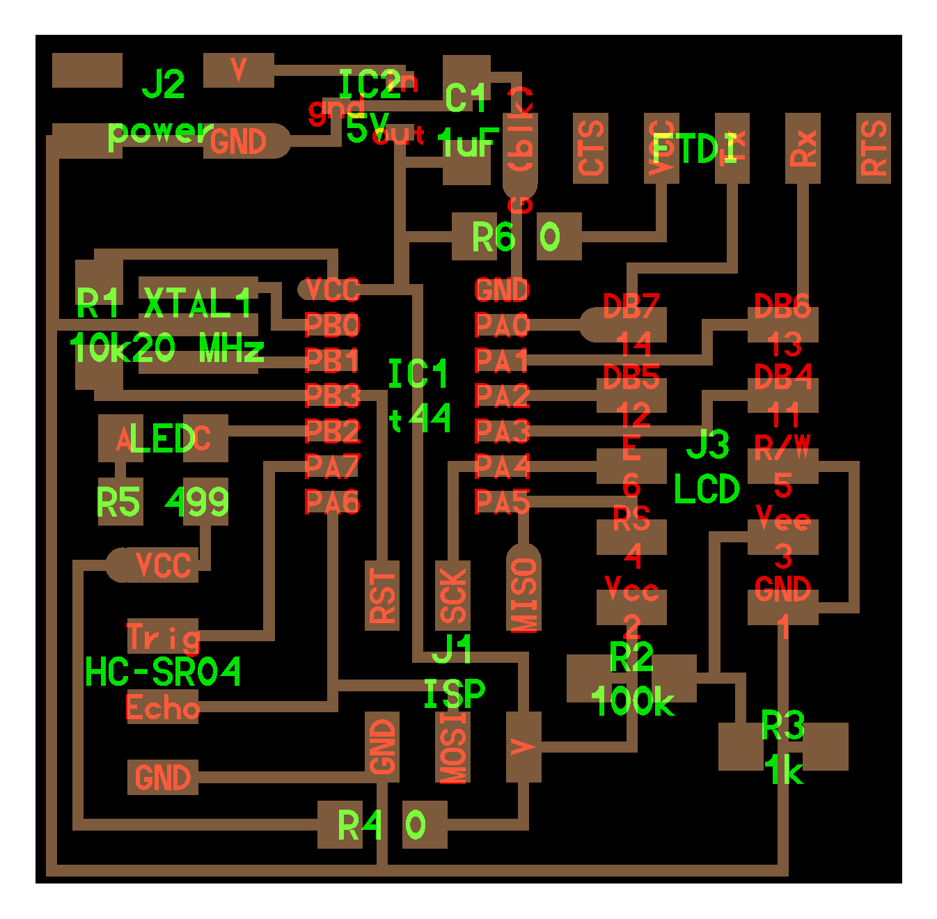
I decided to make a the Ultrasonic Sensor(HC-SR04) circuit board. After refering some previous year student's documentations of input devices I decided create the board using kokopelli. Here I created for adding a 4x1 pin HC-SR04 sonar. Then I added LCD pin and LED into this board.
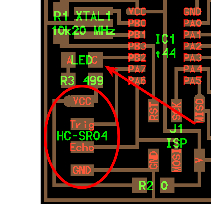
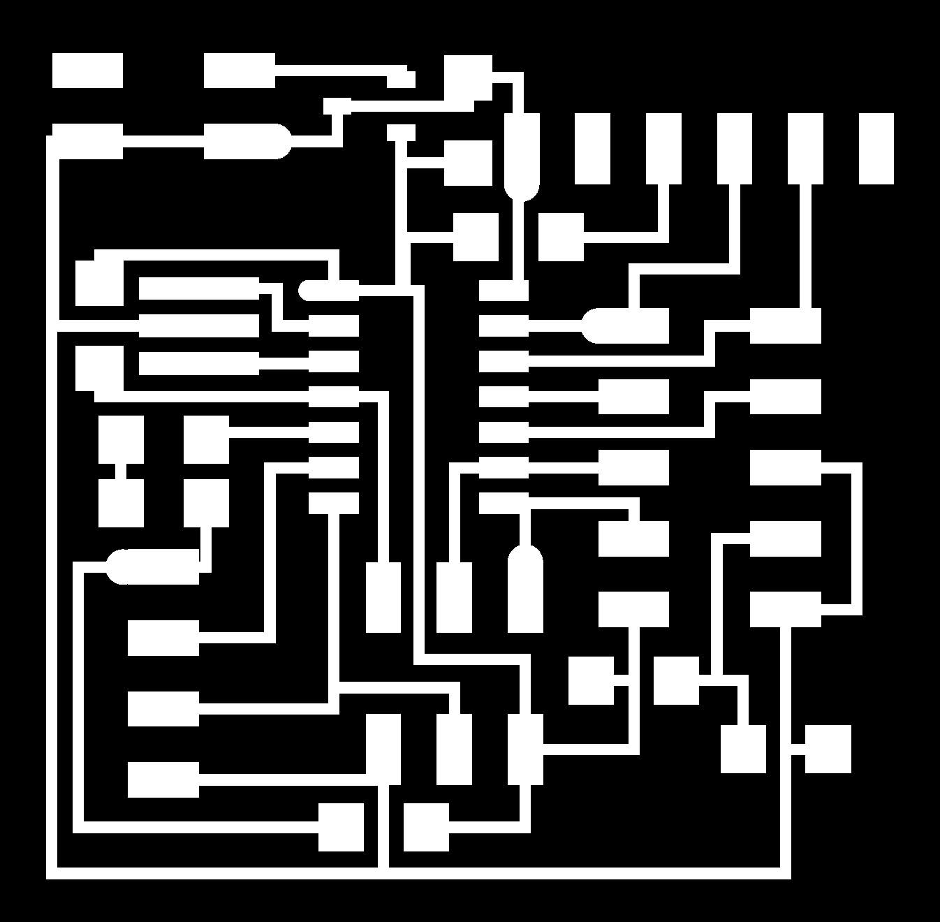
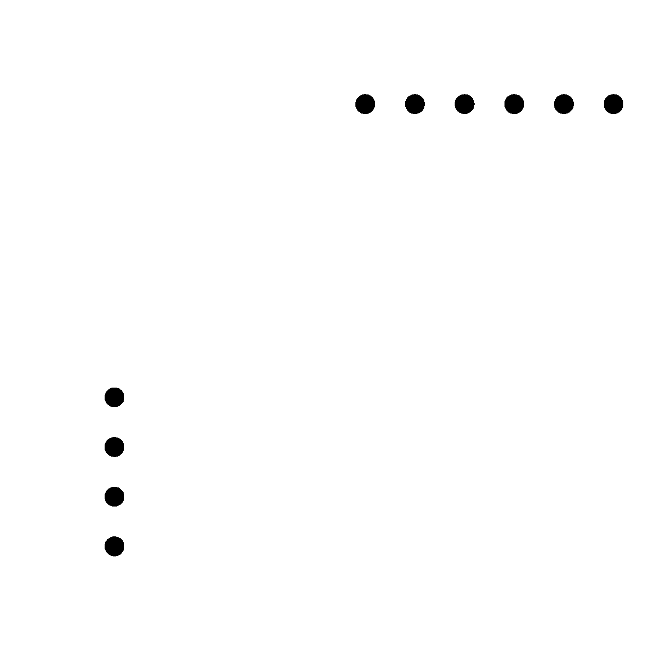
after compleating the desgining of PCB I generate traces, holes and interior.

here this is the code which I added to kokopeli library.
class header_4x1(part):
   #
   # 4-pin header
   # fci 95278-101a04lf bergstik 4x1x0.1"
   #
   def __init__(self,value=''):
      self.value = value
      self.pad = [point(0,0,0)]
      self.labels = []
      #
      # pin 1
      #
      self.shape = translate(pad_header,0,.15,0)
      self.shape = add(self.shape,cylinder(-.057,.15,0,0,.025))
      self.pad.append(point(0,.15,0))
      self.labels.append(self.text(self.pad[-1].x,self.pad[-1].y,self.pad[-1].z,'VCC'))
      #
      # pin 2
      #
      self.shape = add(self.shape,translate(pad_header,0,.05,0))
      self.pad.append(point(0,.05,0))
      self.labels.append(self.text(self.pad[-1].x,self.pad[-1].y,self.pad[-1].z,'Trig'))
      #
      # pin 3
      #
      self.shape = add(self.shape,translate(pad_header,0,-.05,0))
      self.pad.append(point(0,-.05,0))
      self.labels.append(self.text(self.pad[-1].x,self.pad[-1].y,self.pad[-1].z,'Echo'))
      #
      # pin 4
      #
      self.shape = add(self.shape,translate(pad_header,0,-.15,0))
      self.pad.append(point(0,-.15,0))
      self.labels.append(self.text(self.pad[-1].x,self.pad[-1].y,self.pad[-1].z,'GND'))
      #
      # holes
      #
      self.shape = add(self.shape,translate(hole_screw_terminal,0,.15,0))
      self.shape = add(self.shape,translate(hole_screw_terminal,0,.05,0))
      self.shape = add(self.shape,translate(hole_screw_terminal,0,-.05,0))
      self.shape = add(self.shape,translate(hole_screw_terminal,0,-.15,0))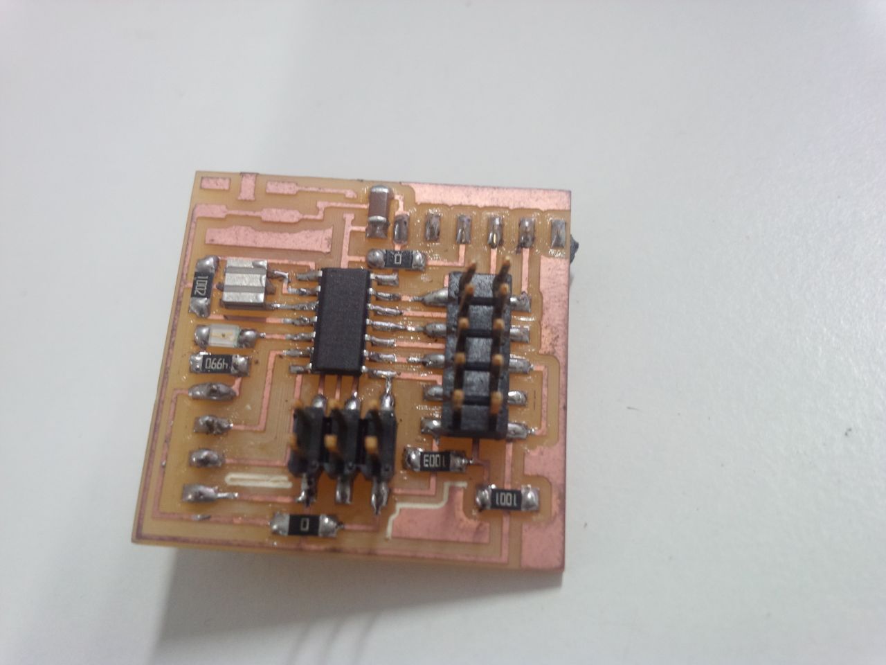
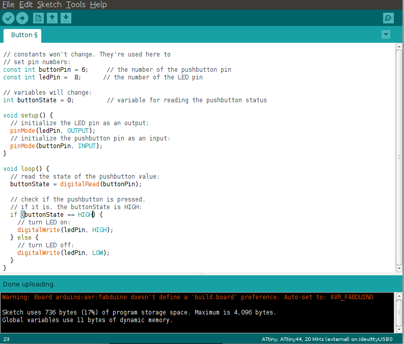
Programming Distance sensor
Using arduino IDE I traied the programming. after done the programming the distance sensor I tried r to calibrate my device. I display the inches and centimeters.
 #include <SoftwareSerial.h>
SoftwareSerial mySerial(0, 1);
const int trigPin = 7;
const int echoPin = 6;

void setup() {
 //initialize serial communication:
 mySerial.begin(9600);
}

void loop()
{
  // establish variables for duration of the ping,
  // and the distance result in inches and centimeters:
  long duration, inches, cm;

  // The sensor is triggered by a HIGH pulse of 10 or more microseconds.
  // Give a short LOW pulse beforehand to ensure a clean HIGH pulse:
  pinMode(trigPin, OUTPUT);
  digitalWrite(trigPin, LOW);
  delayMicroseconds(2);
  digitalWrite(trigPin, HIGH);
  delayMicroseconds(10);
  digitalWrite(trigPin, LOW);

  // Read the signal from the sensor: a HIGH pulse whose
  // duration is the time (in microseconds) from the sending
  // of the ping to the reception of its echo off of an object.
  pinMode(echoPin, INPUT);
  duration = pulseIn(echoPin, HIGH);

  // convert the time into a distance
  inches = microsecondsToInches(duration);
  cm = microsecondsToCentimeters(duration);

  mySerial.print(" Measured Distance is  ");
  mySerial.print(inches);
  mySerial.print(" in, ");
  mySerial.print(cm);
  mySerial.print(" cm.");
  mySerial.println();

 //delay(250); //pause to let things settle
  delay(100);
}
long microsecondsToInches(long microseconds)
{
  // According to Parallax's datasheet for the PING))), there are
  // 73.746 microseconds per inch (i.e. sound travels at 1130 feet per
  // second).  This gives the distance travelled by the ping, outbound
  // and return, so we divide by 2 to get the distance of the obstacle.
  // See: http://www.parallax.com/dl/docs/prod/acc/28015-PING-v1.3.pdf
  return microseconds / 74 / 2;
}
long microsecondsToCentimeters(long microseconds)
{
  // The speed of sound is 340 m/s or 29 microseconds per centimeter.
  // The ping travels out and back, so to find the distance of the
  // object we take half of the distance travelled.
  return microseconds /29 / 2;
}
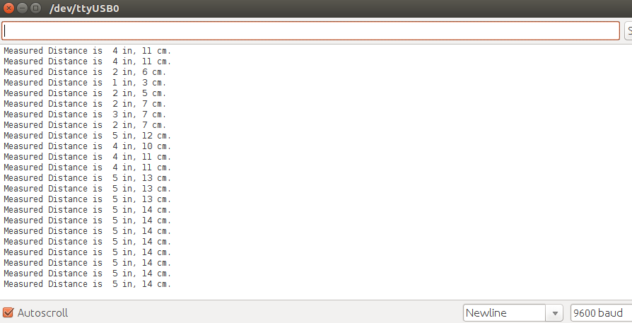
Serial monitering using arduino IDE. The output verified.
Calibration of Distance sensor
For calibrating the distance sensor I created a setup using measuring ruler . Sticked it on the table and placed the device on the end Zero. And I created obstracle on different distance...
Its awesome result which noteiced. its so accurate to the referce scale.
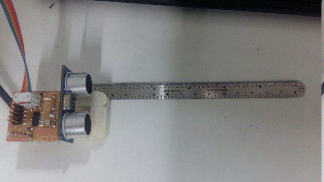
here the procedure which i did.
Sound Sensor(Mic)
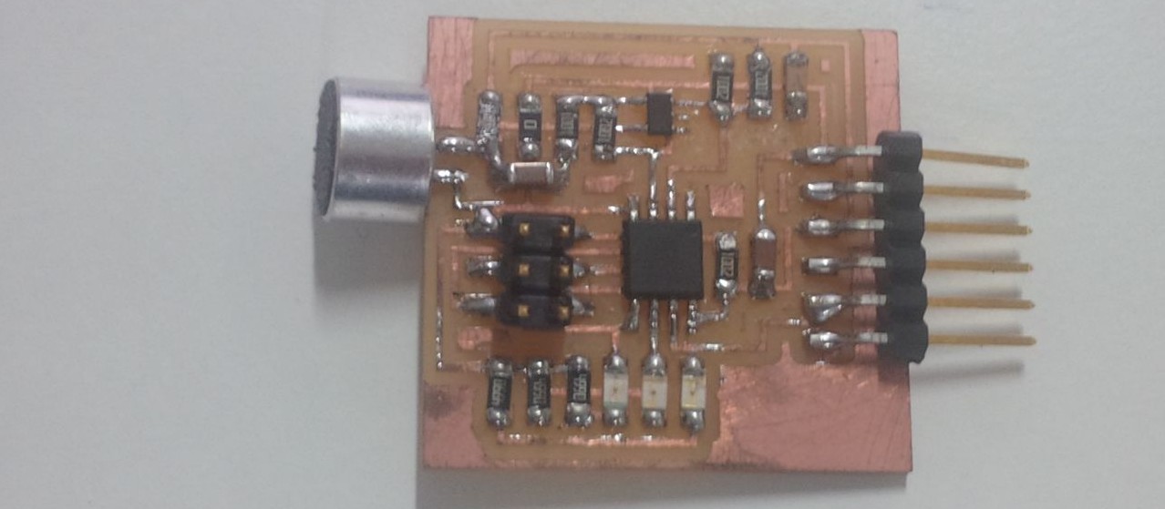
Making the Circuit Board
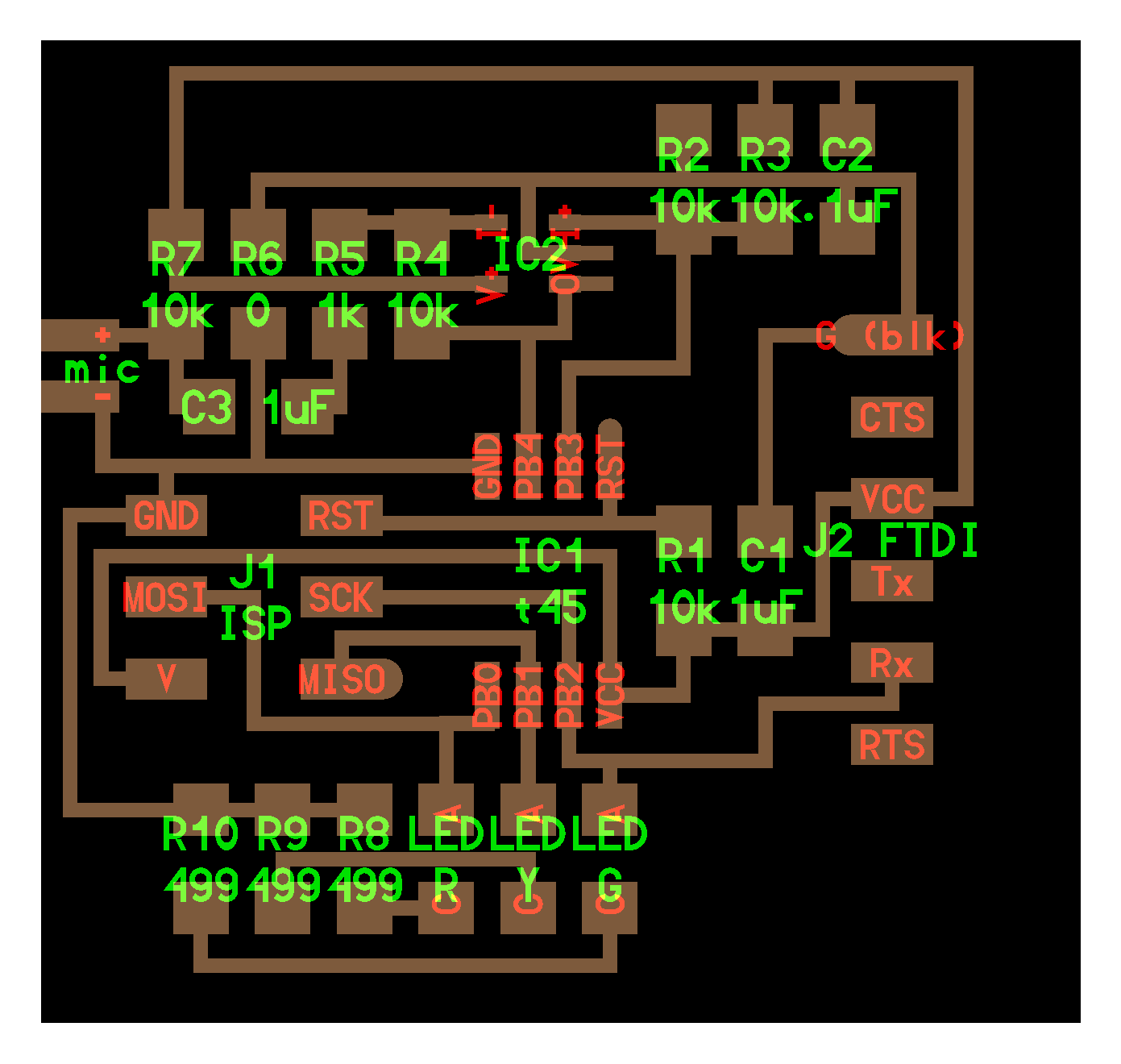
I decided to make a the mic circuit.After refering some previous year student's documentations of input devices I decided to redesign Neil's design of mic. Edited in kokopeli. Added
Then using switch to board option,by arranging and tracing the paths I completed the board.During tracing I needed to change the grid sizes for proper spacing.
Then I milled and stuffed the board with required components.
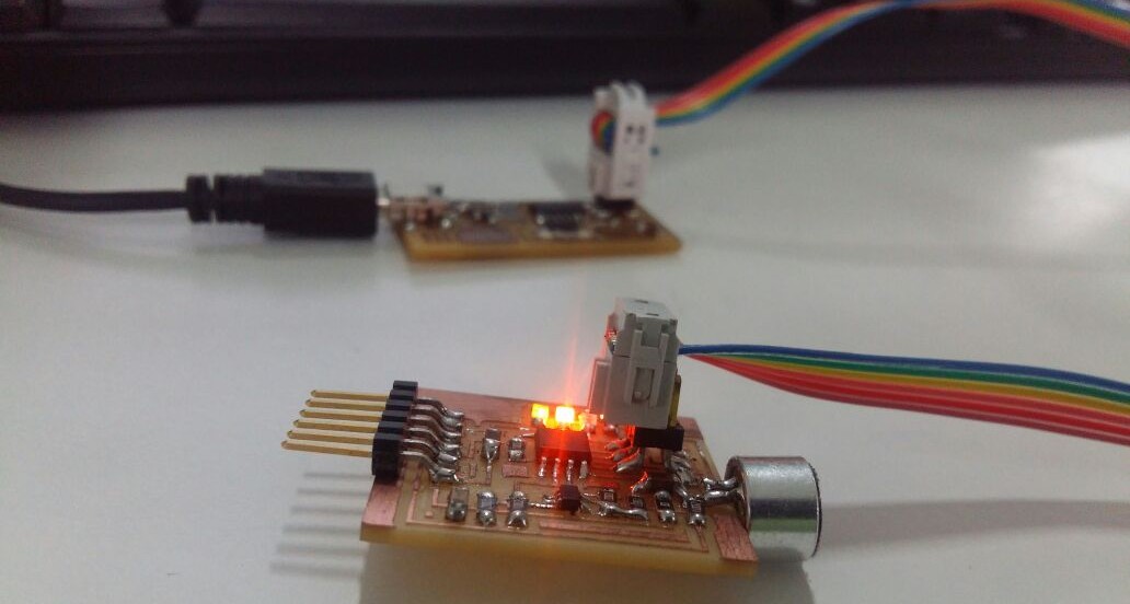
To program the baard first i had to download hello.mic.45.c ,makefile, hello.mic.45.py,python,I used fabISP to program the board.Connect the board and fabISP together and also with computer. For compiling program to hex use the following code:
sudo make -f hello.mic.45.make
code used to program:
sudo make -f hello.mic.45.make program-usbtiny
The programming strats which disply this exprestions on the terminal.
avr-objcopy -j .text -O ihex hello.mic.45.out hello.mic.45.c.hex;\
 avr-size --mcu=attiny45 --format=avr hello.mic.45.out

 AVR Memory Usage
  ----------------
 Device: attiny45

 Program:     500 bytes (12.2% Full)
 (.text + .data + .bootloader)

 Data:        200 bytes (78.1% Full)
 (.data + .bss + .noinit)


 avrdude -p t45 -P usb -c usbtiny -U flash:w:hello.mic.45.c.hex

 avrdude: AVR device initialized and ready to accept instructions

 Reading | ################################################## | 100% 0.00s

 avrdude: Device signature = 0x1e9206
 avrdude: NOTE: FLASH memory has been specified, an erase cycle will be performed
 To disable this feature, specify the -D option.
 avrdude: erasing chip
 avrdude: reading input file "hello.mic.45.c.hex"
 avrdude: input file hello.mic.45.c.hex auto detected as Intel Hex
 avrdude: writing flash (500 bytes):

 Writing | ################################################## | 100% 0.87s


 avrdude: 500 bytes of flash written
 avrdude: verifying flash memory against hello.mic.45.c.hex:
 avrdude: load data flash data from input file hello.mic.45.c.hex:
 avrdude: input file hello.mic.45.c.hex auto detected as Intel Hex
 avrdude: input file hello.mic.45.c.hex contains 500 bytes
 avrdude: reading on-chip flash data:

 Reading | ################################################## | 100% 1.00s


 avrdude: verifying ...
 avrdude: 500 bytes of flash verified

 avrdude: safemode: Fuses OK

 avrdude done.  Thank you.
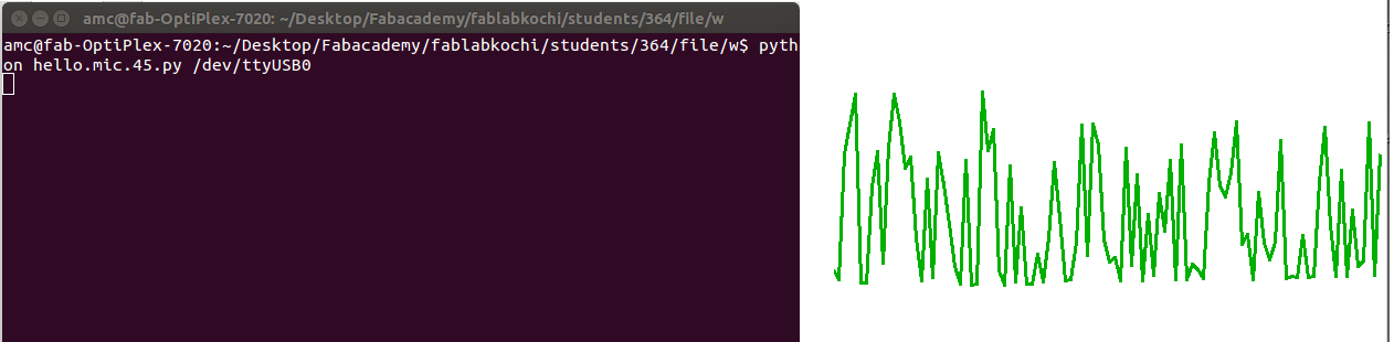
Testing
I made a four pin ribbon cable and connected it to the board.You need to remove connection to programmer before this.Then I used the example Python program and the FTDI USB to serial cable to communicate with the circuit and display the analog information.To run python program use following code :
python hello..mic.45.py /dev/ttyUSB0