Week 7: Computer-controlled Machining
Homework for this week:
- Make something big.
Design of a synthesizer stand with Autodesk Fusion 360
For this week's assignment we needed to design something big with a CNC milling cutter.
As my project, I decided to make a wooden stand for one of my synthesizers, the
Waldorf Blofeld Keyboard.
In the past, I have briefly looked at the 3D modeling software Rhinoceros which
I think is not easy to master. For this week's work, our fab group started to use Autodesk Fusion 360
because the guys behind the program offer some great tutorials on YouTube. Moreover, the program
is widely appreciated. After learning how to build a simple yet usable laptop stand in
this tutorial, I made my own
parametric design for a stand
without dog bones and
laid flat with dog bones.
Parameterization
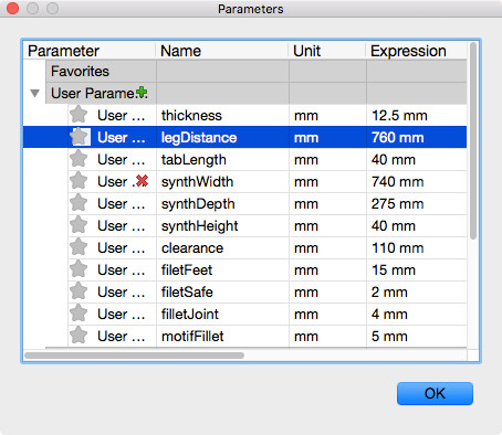
In order to allow for a design that I can change to my heart's content, I used the parameters as shown in
fig. 1.
- thickness Material thickness
- legDistance Inner distance between the legs
- tabLength Length of the tabs in the top plate
- synthWidth Width of the synthesizer
- synthDepth Depth of the synthesizer
- synthHeight Height of the synthesizer at its front
- clearance Distance between table top and plate
- filetFeet Radius of the fillets at the legs
- filetSafe Radius of the safety fillets (fillets at sharp edges)
- filletJoint Radius of the fillets at the joints
- motifFillet Radius of the fillets in the motif in the plate
Design process
I first changed the coordinate system such that the Z-axis goes upward: Preferences/General/"Default Modeling Orientation" = Up,
as this is the orientation I did my first steps with in the laptop stand tutorial.
I cannot detail all steps precisely here. However, I will mention the most important steps that got stuck in my brain.
I first designed a leg. For this, I made a rough sketch of a leg out of straight lines. I set constraints,
for example, I made the top and bottom line parallel, declared some angles a right angle. I also added dimensions to the sketch
such as the length of the line that would later on be the base line for the top plate. Then I did the fillets which gave the leg
a pleasant style, just for eye candy. As already mentioned, for some dimensions I used parameters so to be able to build stands for
different instruments.
I left sketch view and extruded the sketch (Create/Extrude), effectively adding a parametric depth to it. I ended up with one leg
that I needed to duplicate. For this, I clicked the top component in Fusion 360's browser and activated it.
From there, I selected my newly created component, the first leg, and copied and pasted it in place. Duplicating components this way
is important, as I want them to be logically linked and individual components, each of which with its individual history.
I established a logical joint between the legs' faces that face each other. I set their distance using parameter legDistance.
The fact that the component hierarchy matters, and that the individual component histories depend on it, is among the most important
lessons to learn with Fusion 360.
Next I designed a sketch for the top plate. I did not draw the sketch directly on the top face of one of the legs but on a separate
plane. Prior to this I created a new component for the plate. Once the rough outline was finished, I again set constraints, dimensioning and parameterizing some distances.
The plate would have holes for tabs. I found the position for the tabs using construction lines (draw a line, click on it, press 'x')
and the mirror tool. I made the plane with the sketch aligned to the top face of the legs (Modify/Align). I left sketch view and
extruded the plate downward by the parameter thickness, doing so cutting the tabs from the legs.
I got the necessary holes in the top plate by performing a subtraction operation (Modify/Combine with operation "Cut").
For stability, I wanted a support sandwiched between the top plate and the legs. I first created a new component for the support.
Then, I designed an offset plane to the plane through the top faces of the tabs. Then I projected the silhouettes of the legs onto the plane (Sketch/Project).
On the offset plane, I drew a sketch for the support, concretely a rectangle with a width that is the distance between the two legs. Its height equals the thickness of the Multiplex
I would be using. This is identical to parameter thickness. I wanted the top faces of the support and the top faces of the legs making one smooth surface. For this, the
support would have a opening about at its lower part with half the height of the support. The top face of the legs would have tabs that fit to these openings.
For the openings, I added rectangles with thickness as width and half the height of the support as height.
I left sketch mode and extruded the rectangle downward four centimeters, but omitting the rectangle for the opening in the support.
Finally, I added two additional supports at the back of the construction.
For the upper support, I constructed the corresponding sketch on an offset plane that I made parallel to the lower 'horizontal' edge of the leg.
The middle line of the support, seen from aside, would be colinear with the lower 'horizontal' edge of the leg. For the alignment, I used construction lines.
Like before, I extruded the rectangle that were the base area for the support and subtracted the resulting body from the leg's material.
For the lower support, I made a mistake. Instead of creating a new component, I copied the upper support and moved it at its new position.
While the result is usable, the lower support does not appear as an individual component in my design. Instead, it is hierarchically assigned to the upper support.
Eye candy on the top plate
As I like electronic music, and since the stand is meant for a synthesizer, I wanted a nice design for the top plate.
I activated the top plate component and created a plane on it, on which I drew a sketch. The sine-like curve consists of several splines.
The curve on the lower left is made of splines and demanded some manual tweaking. The PWM-like curve on the lower right is made of straight lines. I inserted
fillets at every 90° angle with radius motifFillet.
Dog bones
At places with 90° angles in a design, dog bones are a necessity. You obtain dog bones by adding drill holes with approximately half the diameter of the milling head,
their midpoint being the corner of the 90° angle. With dog bones, you allow the milling head to change its direction at the right position when it is already within
the work piece.
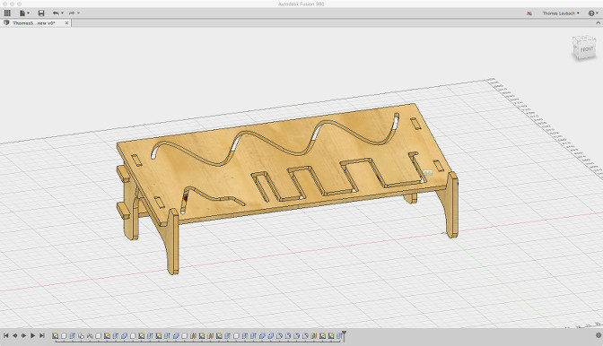
Fillets
In the entire design, see fig. 2, I added fillets with a parameterized radius to all sharp corners, so to prevent injury, and some fillets just for the sake of prettiness.
Preparing for CAM
For the CAM process, the holes for the dog bones, the inner contours and the outer contours need to be separated as they require
different tool paths. For this, many 3D modeling applications offer layers. Unfortunately, Fusion 360 does not.
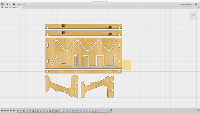
Instead, the strategy I followed in Fusion 360 was this: I laid all components in my design flat on the same surface (cf. fig. 3), with their best side all on top.
After that, I exported the
result in DXF format,
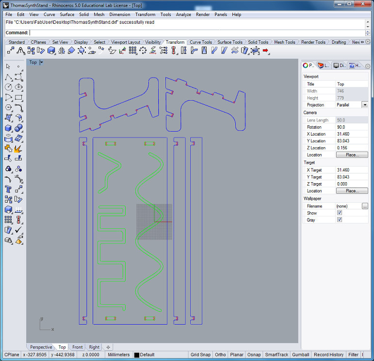
then re-opened the file in Rhinoceros. There, I sent the holes, the outer and the inner contours onto separate, individually colored layers.
The result is displayed in fig. 4.
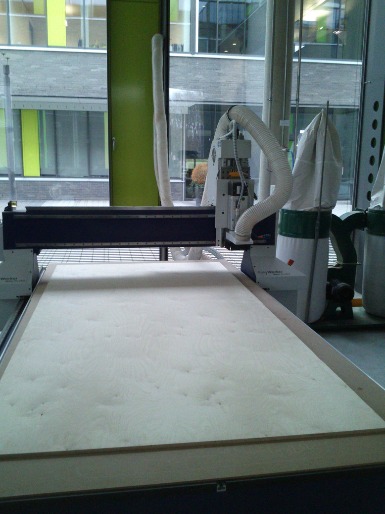
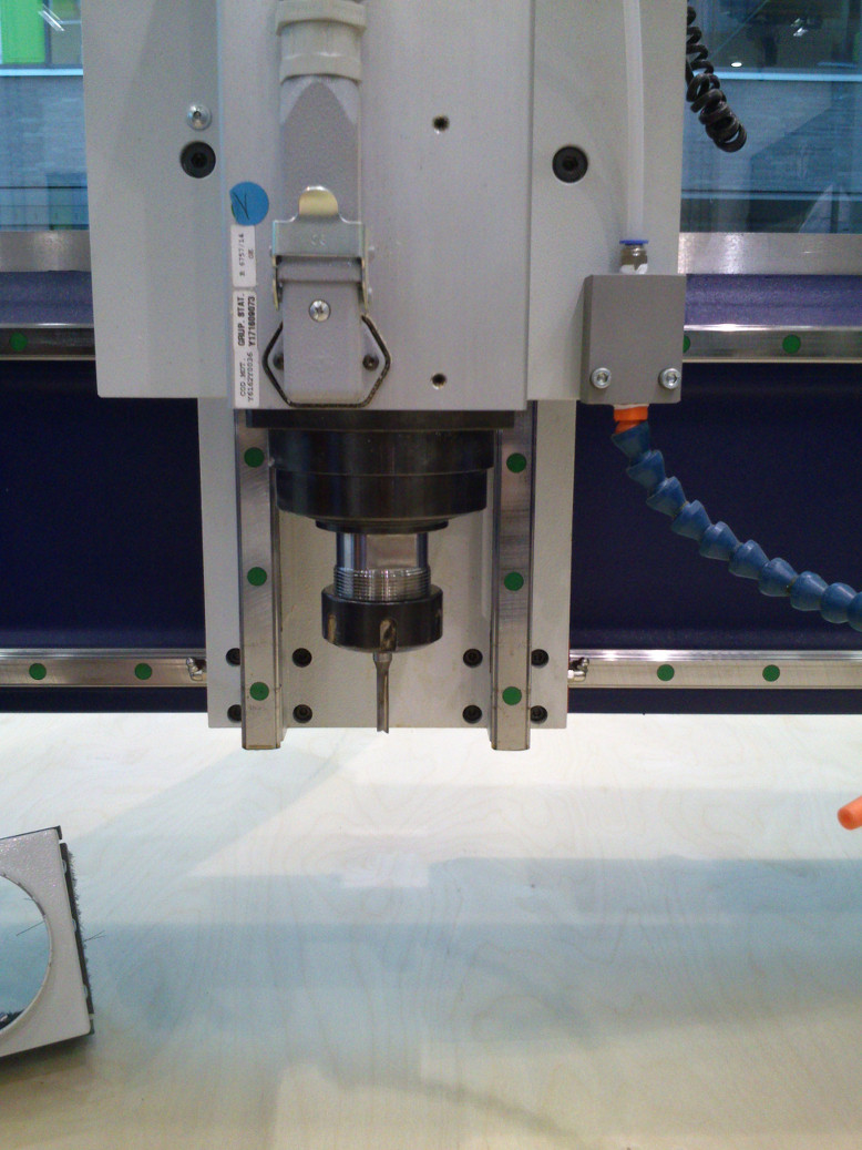
Preparing the CNC milling cutter
In our FabLab we use the CNC portal milling machine
e(sign EasyWorker MasterPro 2513 (see below figs. 5 and 6).
The software for the machine goes by the name e(sign CNC 4.0.1. The machine allows four alternatives for tool paths: pocket, offset (inside or outside cut), engrave (cuts centric) and drilling.
Our colleague Karsten Nebe wrote a very good tutorial on the e(sign EasyWorker MasterPro 2513 milling machine
and showed us how to prepare and use the machine. While I will not paraphrase his tutorial, I will add here some issues that stuck to my mind:
The software of the milling cutter does not check in advance whether the tool paths work from start to end.
This means I need to check them directly on-screen. Moreover, if the file is broken, the software displays nothing at all.
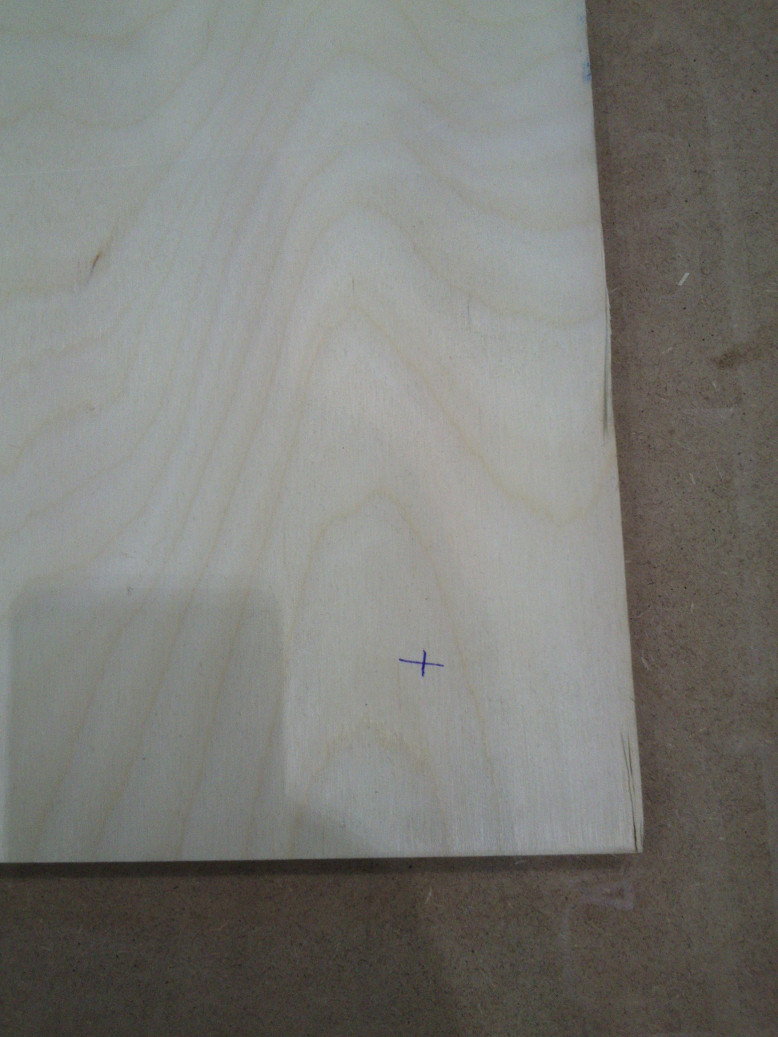
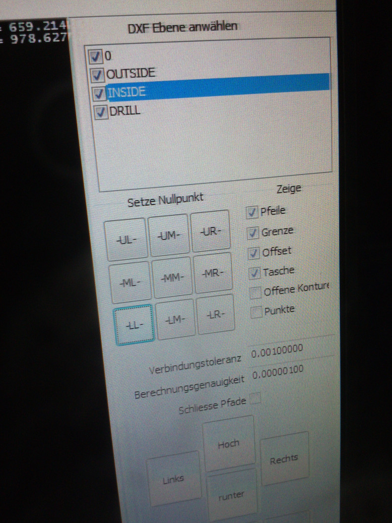
The point of origin in the coordinate system of the milling cutter and that in a design's coordinate system almost always differ.
Regarding my specific design, its point of origin is at the lower left whereas that of the machine at the lower right towards the front of the bed.
In order to account for discrepancies such as this, the machine's software offers a tool for this (cf. figs. 7 and 8).
With a pump, the table for the milling machine creates a vacuum, thereby fixing the work pieces on it at their positions.
On the front of the table, you may select in which zones beneath the table's surface the vacuum becomes active. It is important to
select these zones before milling, as otherwise, work pieces that have only a minor connection with the rest of the material may lose contact
to the table and move, rendering your product unusable.
In our initial experiments, we fixed the wooden boards to the table not only via vacuum but also with screws. Luckily, this proved nonessential
for subsequent works.
When I was doing my design for the stand, I tried to lay the pieces out as parsimonious as possible, so as to not waste material.
By doing so, I disregarded the relationship between the width of the bridges between the individual parts and the diameter of the milling head. During milling, this would result in rough or garbled edges in
the pieces because the milling head's diameter simply is too large. This means: make the bridges between the parts in the material wide enough for the extruder head.
Building the synthesizer stand
In general, with our equipment, milling of a work piece is at least a three-stage process:
- Drilling the holes for the dog bones.
- Milling the inner cuts.
- Milling the outer cuts, i.e., cutting out the pieces from wood.
For every stage in the milling, there is a correspondent layer in the design - and in the DXF file.
The holes for the dog bones I made first, then the inner contours, then the outer contours, finally I would
sandpaper the rough edges at the work pieces.
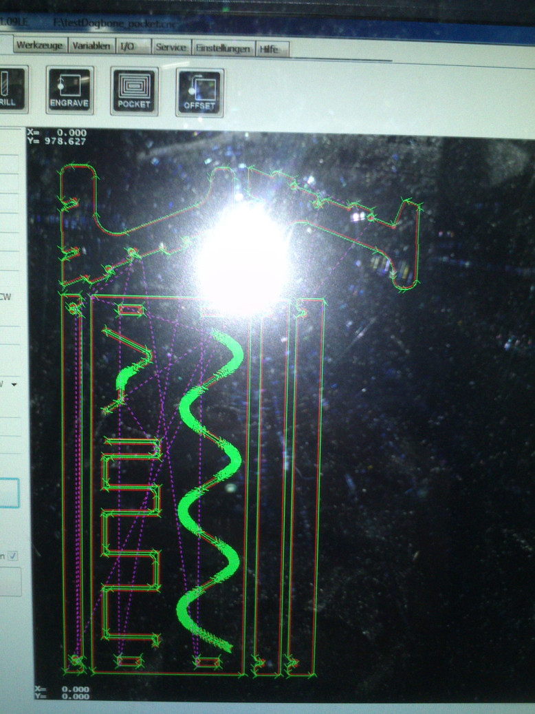
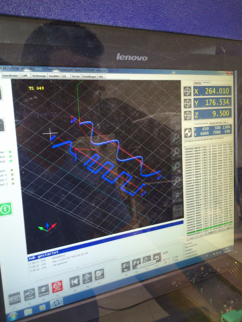
Fig. 9 shows all tool paths for my design. Although this view is good for an overview, it is necessary to inspect
the tool paths for every DXF layer individually. If the DXF file were damaged, the machine would not depict the tool path at
all, but simply displaying nothing.
Drilling
In my design, the holes for the dog bones were the only structures to drill.
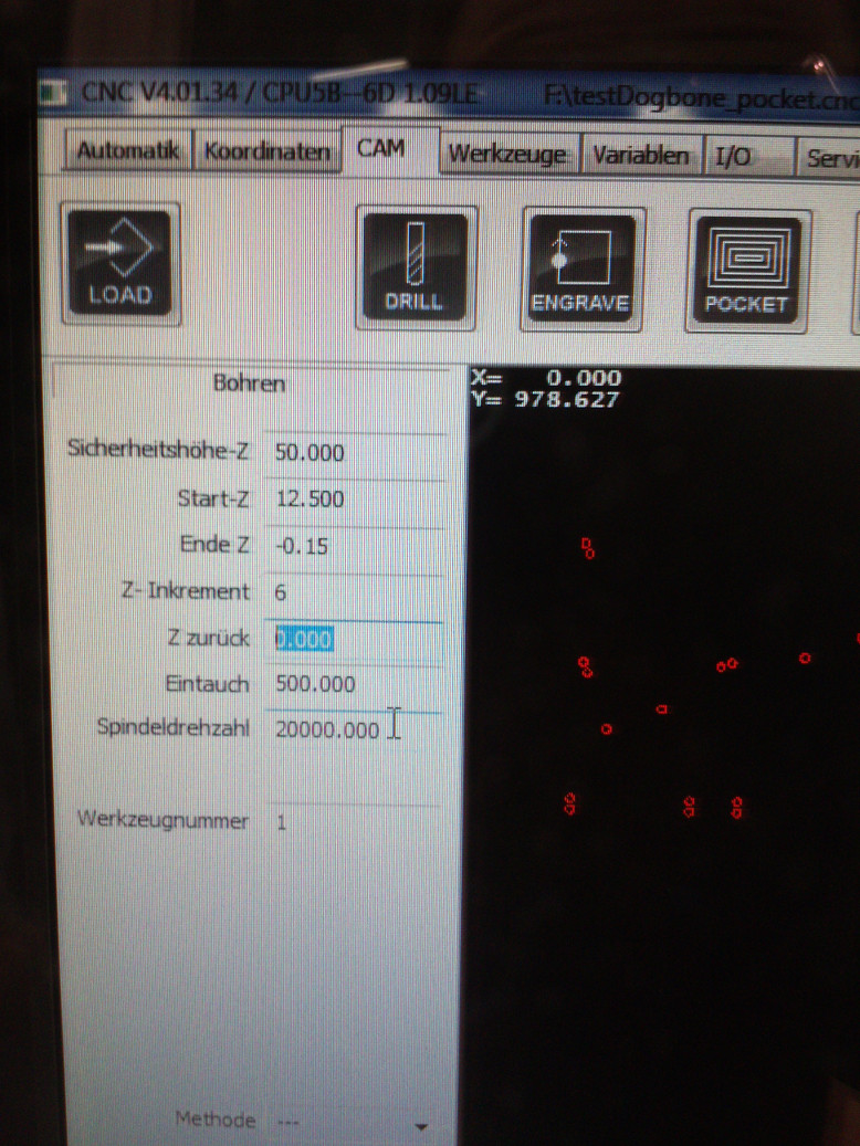
I used the following parameters with our milling machine (see fig. 10):
- Safety height-Z (Sicherheitshöhe): 50.000
- Start-Z: 12.500
- End-Z (Ende-Z): -0.15
- Z-Increment (Z-Inkrement): 6
- Z backwards (Z zurück): 0.0
- Spindle speed (Spindeldrehzahl): 20000.0
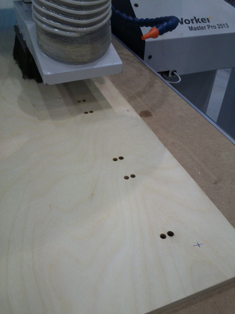
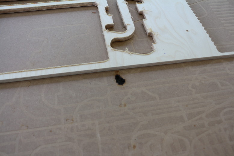
During the drilling (fig. 11), I noticed that the holes the machine had drilled in the multiplex wood were covered with a dark coating. We were puzzled as I was using the very same parameters as my colleagues did when they were milling their pieces. After I had lowered the spindle speed, the machine no longer produced a dark coating. When the milling process was over, we inspected the pieces and were pleased. In particular the rounded edges on the top plate were smooth and delicate. However, we noticed deep burn marks on the cover sheet where some holes in my design were (cf. fig. 12). It turned out that the vendor who sells us our machine tools has inadvertently provided the wrong milling head for the job we had specified. The head we were using was suited for milling grooves but not for drilling.
Inner cuts
I started to mill the inner structures (cf. fig. 13) with spindle speed (Spindeldrehzahl) 20000.
While the surfaces the machine produced were acceptable, I lowered the spindle speed
to 7000. This resulted in noticeably smoother surfaces with less shavings.
For the inner cuts, I used following parameters (see fig. 14):
- Safety height-Z (Sicherheitshöhe): 50.000
- Start-Z: 12.500
- End-Z (Ende-Z): -0.01
- Z-Increment (Z-Inkrement): 3
- Form feed (Geschwindigkeit): 500
- Thrust speed (Eintauch Vorschub): 500.000
- Spindle speed (Spindeldrehzahl): 20000.0
- Spindle direction (Spindelrichtung): CW (clockwise)
- Method (Methode): inside clockwise (Innen CCW)
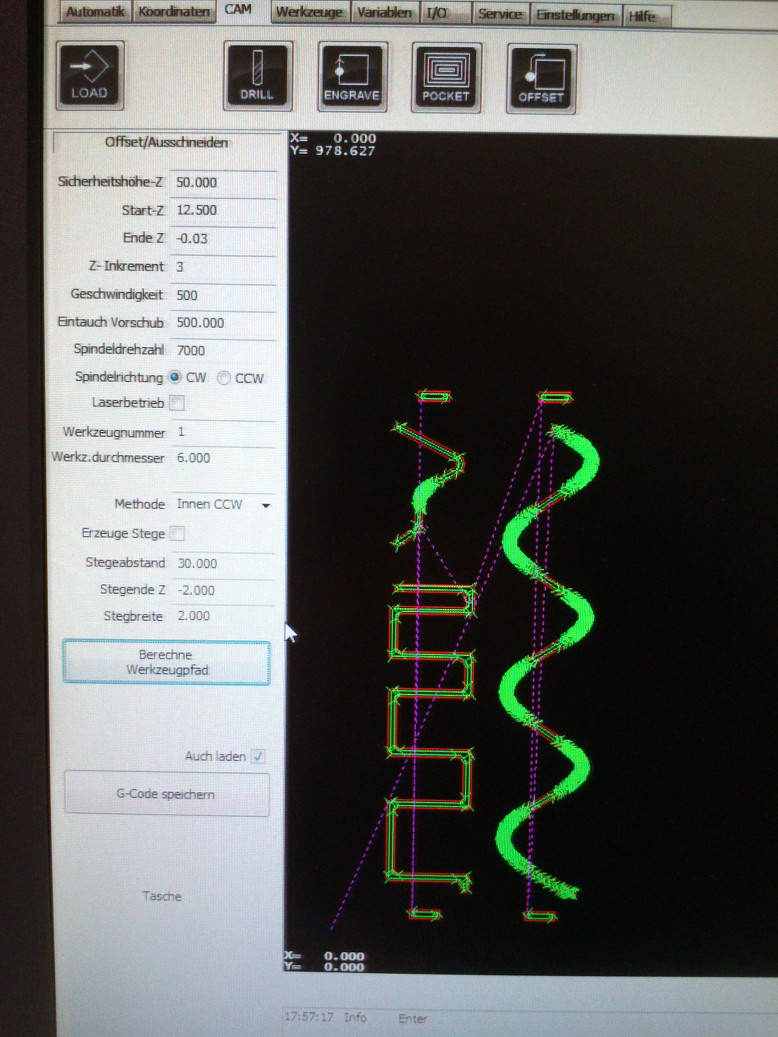
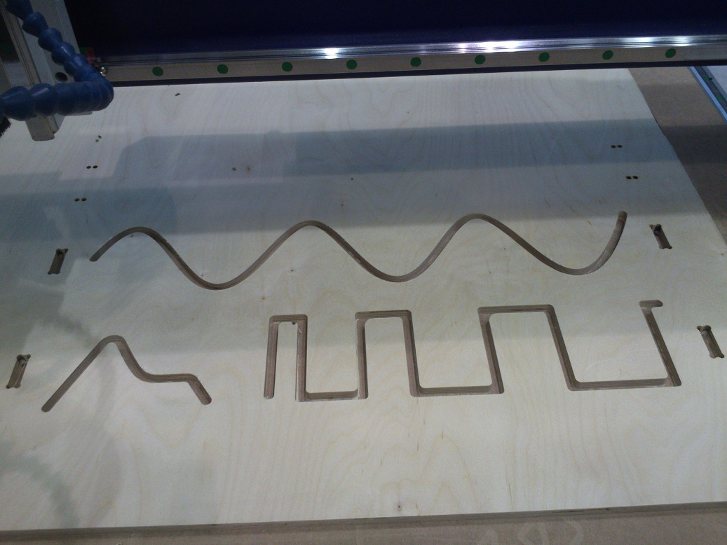
Most of the inner cuts already visible (fig. 15). With the lowered speed, I was astounded how smooth
the curvatures were.
Outer cuts
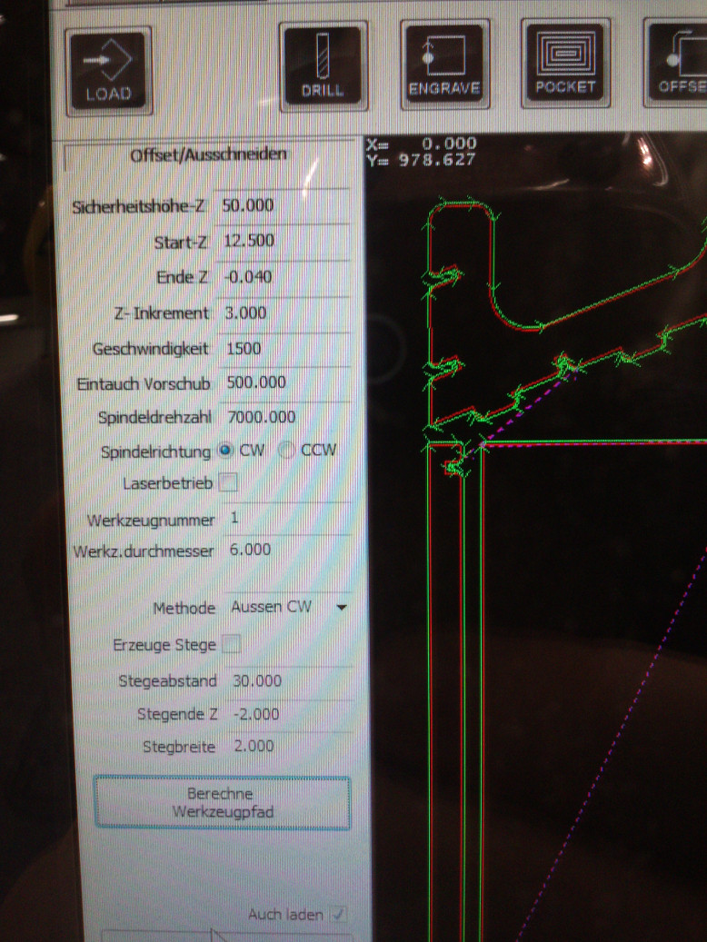
I set the parameters (see fig. 16) as following:
- Safety height-Z (Sicherheitshöhe): 50.000
- Start-Z (Start-Z): 12.500
- End-Z (Ende-Z): -0.040
- Z-Increment (Z-Inkrement): 3
- Form feed (Geschwindigkeit): 1500
- Thrust speed (Eintauch Vorschub): 500.000
- Spindle speed (Spindeldrehzahl): 7000.0
- Spindle direction (Spindelrichtung): CW (clockwise)
- Method (Methode): outside clockwise (Aussen CCW)
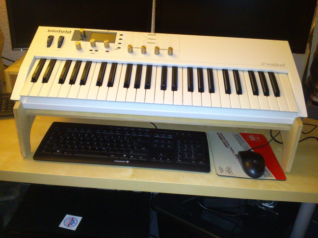
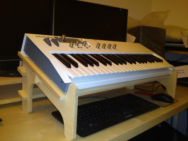
The finished stand
I like my synth stand (figs. 17 and 18). It turned out that something is wrong with the parameterization of the height of the stand.
I believe I can still use keyboard and mouse - and better watch the monitors - if the synth is lower than now.
I therefore wanted to lower the distance between table top and plate by two centimeters. When I changed the necessary
parameter "clearance" in my design, the model behaved not as I anticipated. This is something
I need to look into. It also turned out that the wood was 0.5 millimeter smaller than I had specified in my design.
While the synth stand I got was fairly stable in general, I had to add several layers of adhesive tape to the tabs of the supports
to hold them in place.
Source files
Design for a Waldorf Blofeld Keyboard synthesizer stand: here
Same design spread on the ground with dog bones: here
DXF file with dog bones: here
Lessons learned
- I learned how to prepare and use a CNC milling machine.
- I made my first design in Autodesk Fusion 360. I like the way you design volumetric bodies from sketches.
- In general, I like Fusion 360. But it was cumbersome to use Rhino for the preparation of the layers for the CAM.
- The fact that the component hierarchy matters, and that the individual component histories depend on it, is, at least for me, among the most important lessons to learn with Fusion 360.
- Do not trust in your initial measurement of your material's thickness. Measure again.