How to MAKE it
At the FabLab Kamp-Lintfort we have a Epilog Fusion 60Watt Laser. The machine has a work space of 1000mm x 700mm.

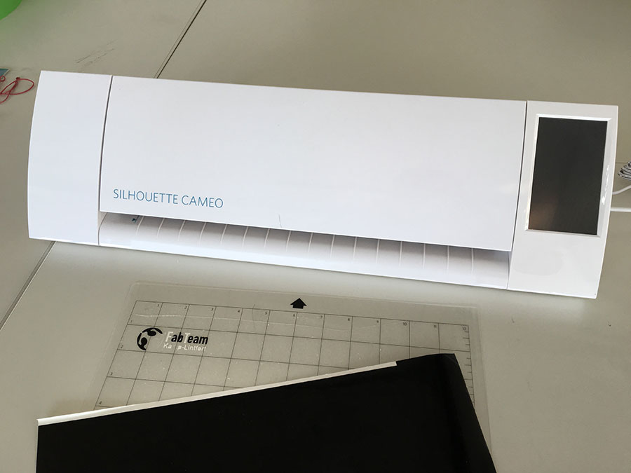
For (vinyl) cutting we have a Summa S120 Cutter and a Sillouette Cameo.

MAKE something with the vinyl cutter - a sticker
- I used the FabLab Logo I made in Adobe Illustrator recently and exported it to .png
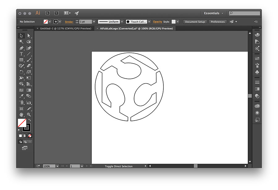
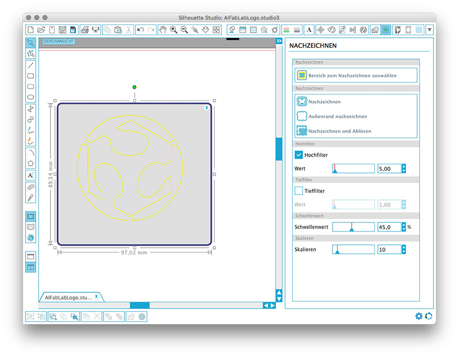
- This time I used the Sillouette Cameo cutter and its Software Sillouette Studio (free). I opened the .png file and scaled it to the proper dimensions.
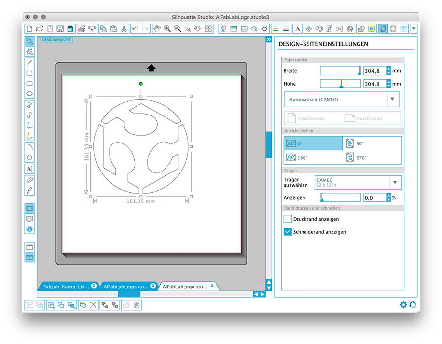
- I used the "redraw" function in order to identify the outlines.
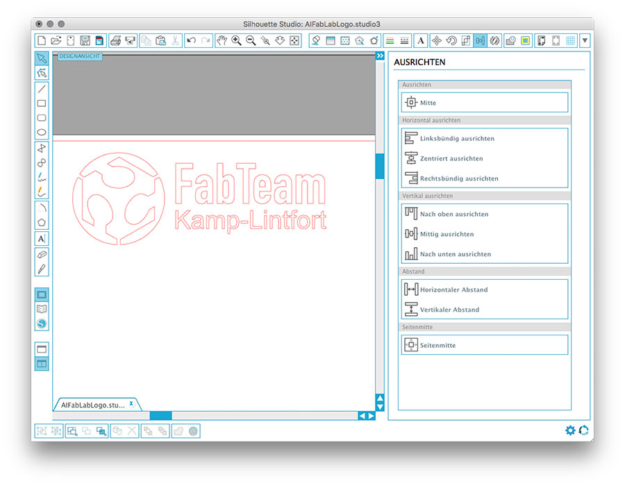
- I added two text boxes, set the propper sizes and positioned them.
- A simple box makes handling and detaching of unwanted vinyl parts easier. After preparation of the cutter, the job can be sent to it.

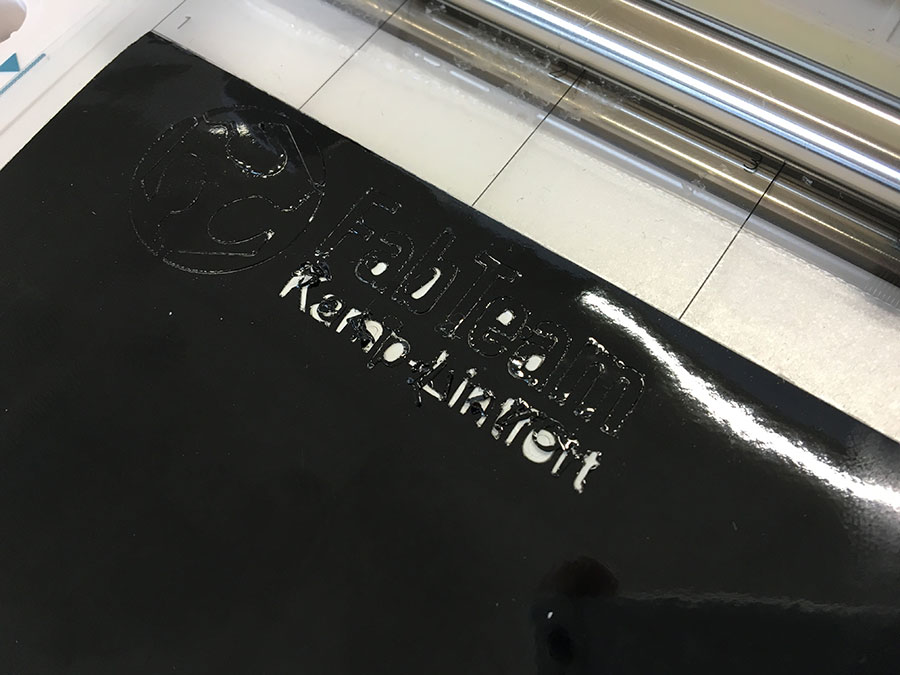
- Black vinyl was attached to the cutting support pad.

- Trusting the programs preferences, I set the cut depth to 5.
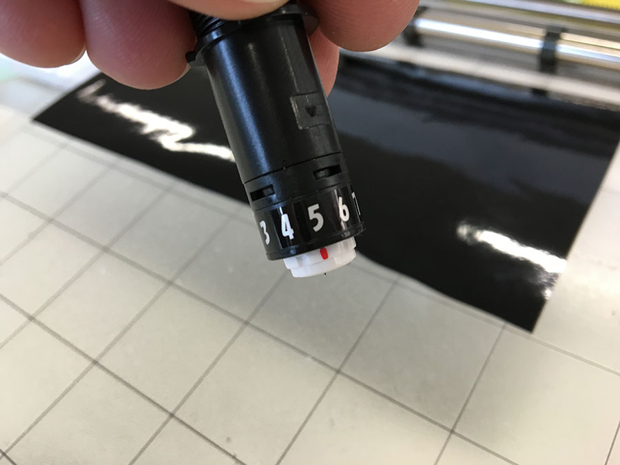
- ... which was a mistake. At the end (after several tests) a cut depth of 1 was appropriate.
- I removed the unneeded vinyl.

- You need transfer foil to 'mirror' the print. Simple press it onto the positive cut.
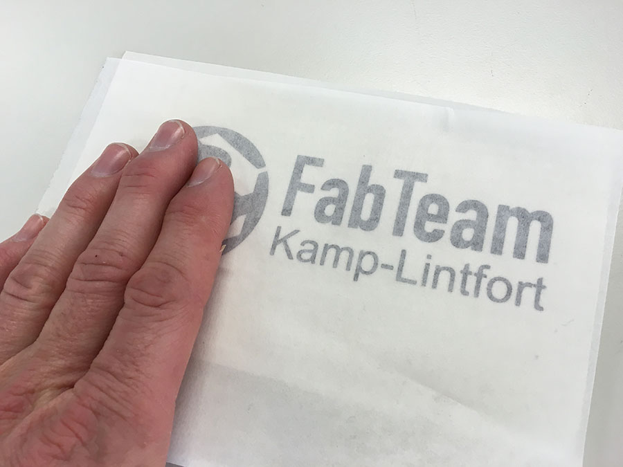
- Gently remove it. Now it is mirrored, sticky part of the vinyl up.

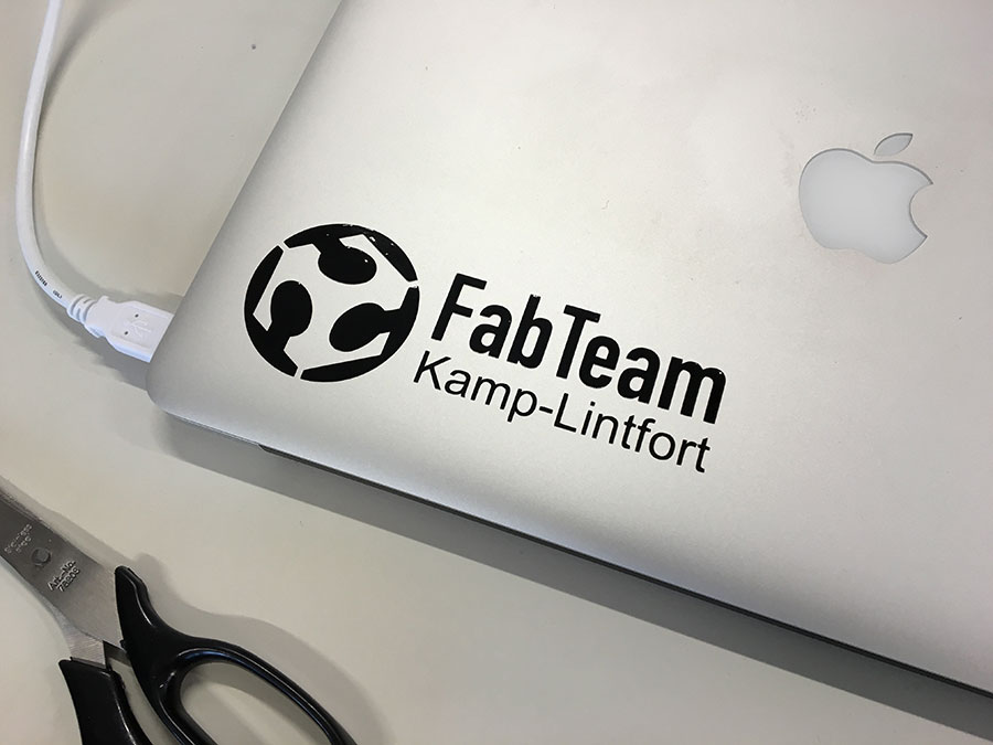
- Place it. Ready :)
Download
MAKE a spaceship
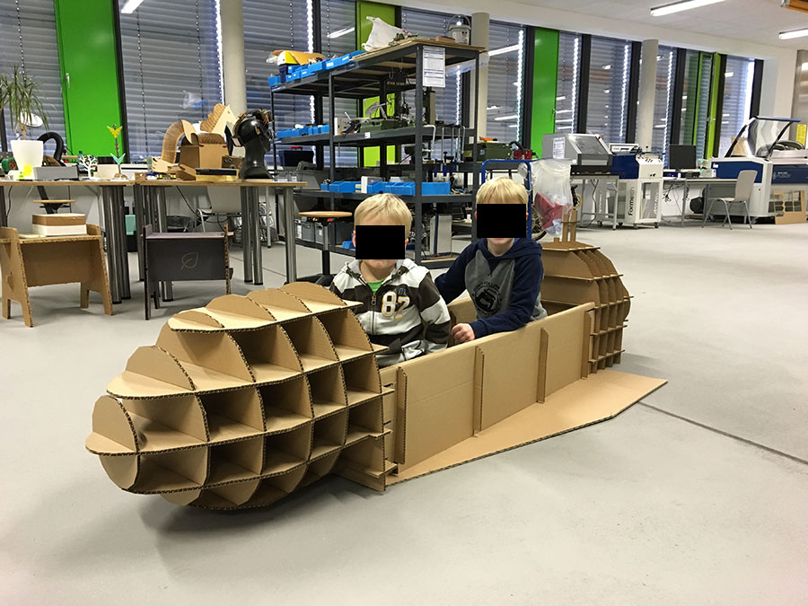
For my sons astronaut-birthday-party he wished to have a real spaceship to play with. Happily I could convince him that a real space ship might be too big for our living room but I promised to do my very best to create an alternative.
May plan was to make a scaled version out of cardboard.
- Initially, I started to experiment with a free 3D model of the spaceship but it turned out to be to complex for 123D Make. Even after reducing the mesh ("ReduceMesh") to a minimum, it took ages to process it in 123DMake. Additionally it seemed as the model was not waterproof, which caused exceptional output in 123DMake.

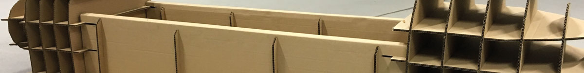
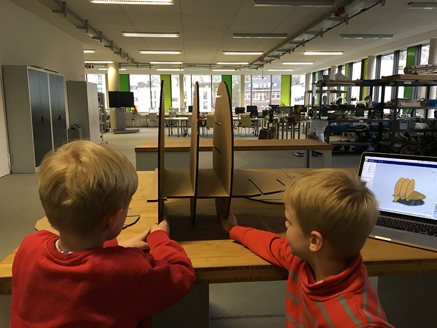
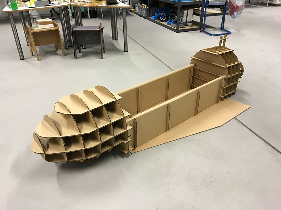
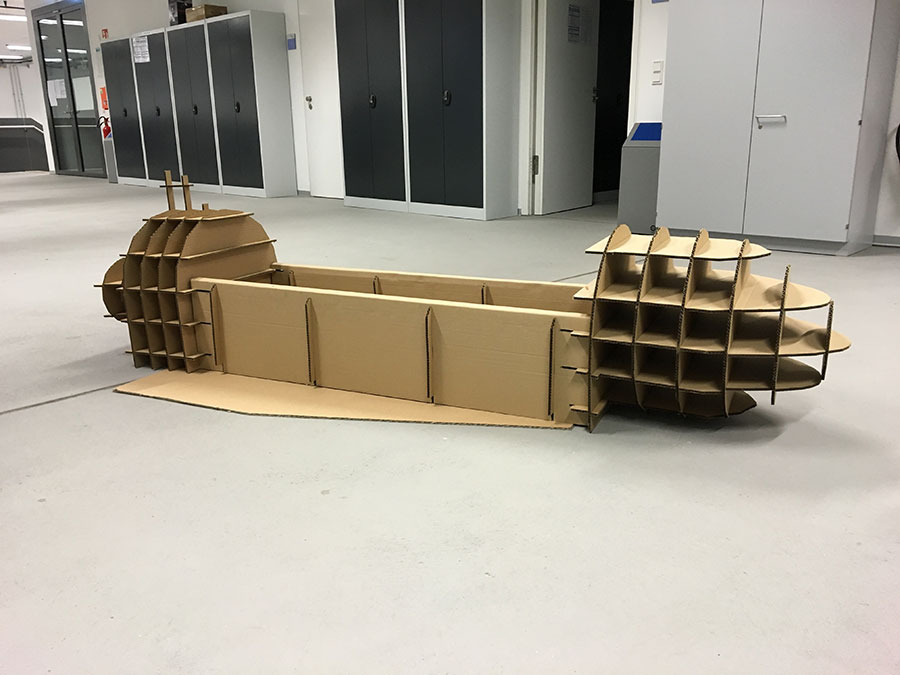
- Thus, I decided to create a way simpler version of the spaceship. It consists of three parts: nose, tail and body. Nose and tail were supposed to be cutted by the laser but the body needed to be made by hand because of the size. It wouldn't fit onto the lasercutters work space.
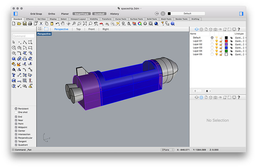
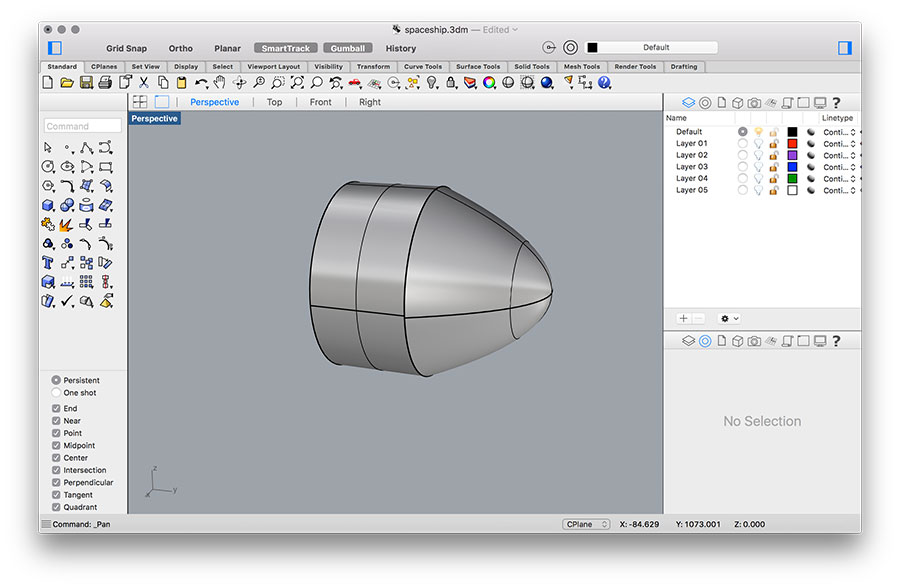
- I started with the spaceships nose. These are simple solid objects (a paraboloid and a cylinder) that have been merged ("BooleanUnion"). The object needs to be exported as .obj for further use in 123DMake.
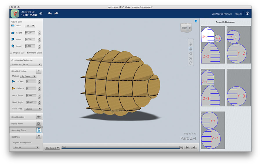
- Open 123D Make. Settings to be made: First, you have to set the sizes of your material (I used custom format so set the material size for our laser cutter 100x60 cm; 0,66cm material thickness). Then, set the dimensions of the object you like to make (here: widh=50cm). As for the construction technique I have choosen "Interlocked Slices". Set your preferences in 'Slice Distribution'. You may also want to play with the rest of parameters until you have the design you like.
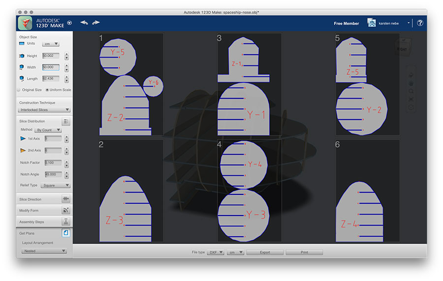
- On the pane "Get Plans" you can see the layout and number of sheets needed. I have exported them as .dxf in cm.
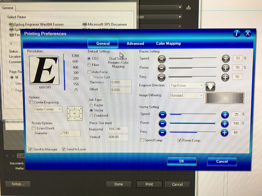
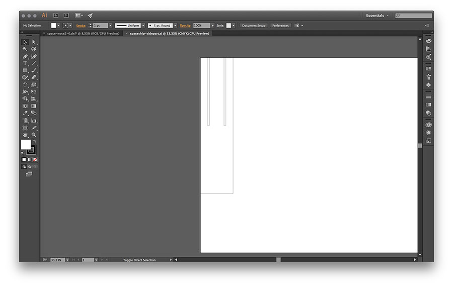
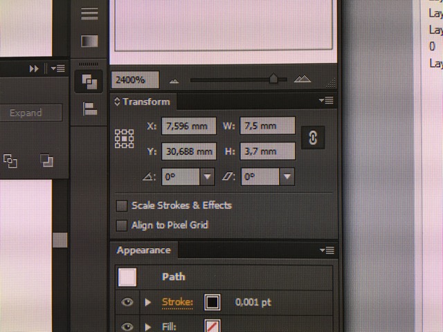
- I used Adobe Illustrator in which I opened the dxf files. In order to cut, you have to set the lines to color black and to the width to 0,001 (otherwise the laser wants to engrave). Settings for the cut of 6,6mm thick cardboard are: Speed 25-30%, Power 100%, Frequency 60%.
When exporting as .dxf, lines/curves are often separated. To all curves belonging together in Illustrator, you can simply select one of them, then click on Select>Same>Fill&Stroke. Group all selected ones and proceed.
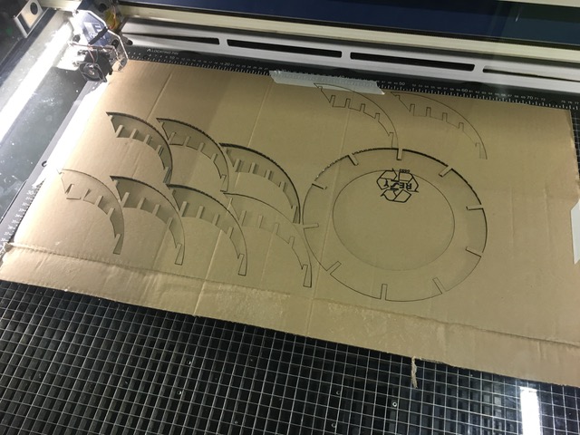
- Finally, all cuts need to be assembled.
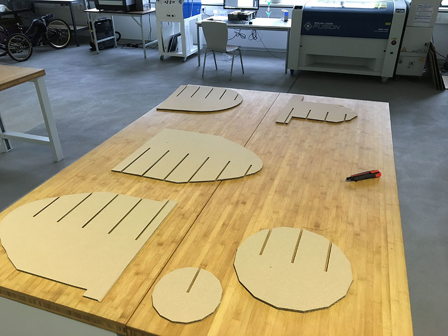
- 123DMake shows each single step on how to assemble the object. Here, my kids helped me ;)
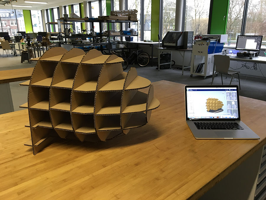
- Finally, the physical spaceships' nose looks like the digital one.
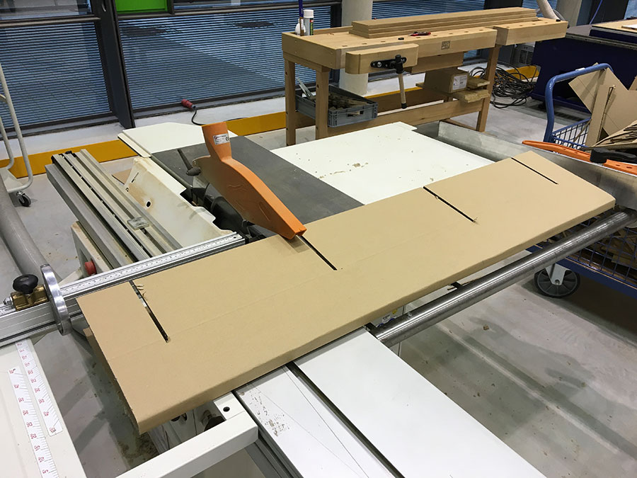
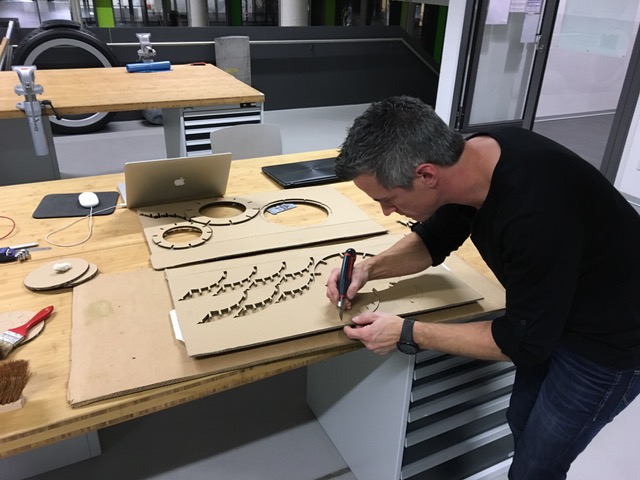
- Because of the length of the side plates I had to make them manually. therefore I folded a piece of cardboard (using an inlay of 2cm) and cutted it with the circular saw. I wanted the side plates to be more resistant and therefore I used press-fit construction, too. I made the kerfs by using the circular saw, too.
- The counter piece was drawn in Illustrator.
- The tail piece of the spaceship was done in a similar way.
At the end we assembled all parts to get a 'real spaceship'. And the kids love it :)
Download
MAKE press-fit lamps
I used Rhino to create the body of the lamp and 123D Make to turn it into a 2D built plan. For the material I choose cardboard (leftover of some packaging).
A press-fit spherical lamp
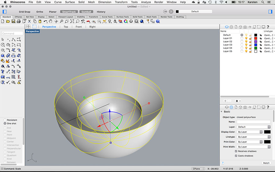
- In Rhino: Make a sphere in the size of the lamp.
- Make another sphere, bigger than the other.
- Drag Gumbal of outer sphere in Z-dim (because you want to have more material at the bottom for the flat cut).
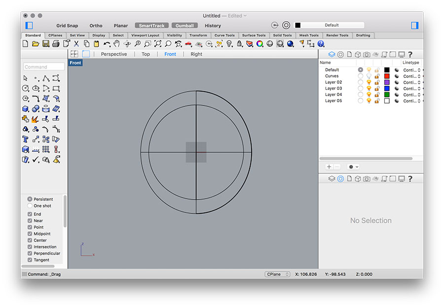
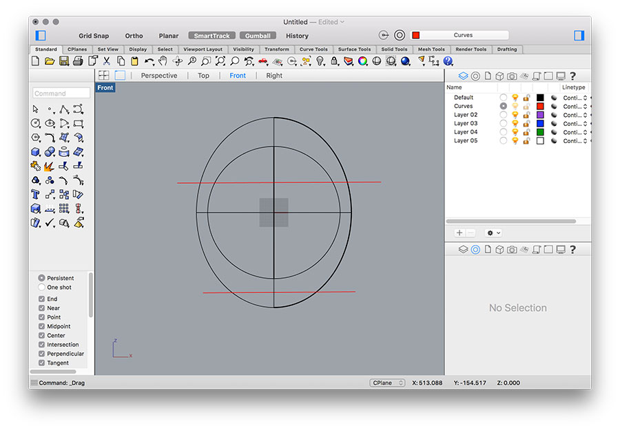
- In Front view draw two lines (for cutting the object).

- Rotate the object, so that you can see the bottom. Use "PlanarSrf" and select the outer curves create a surface.
- Select all. Use "Join" to make it an object.
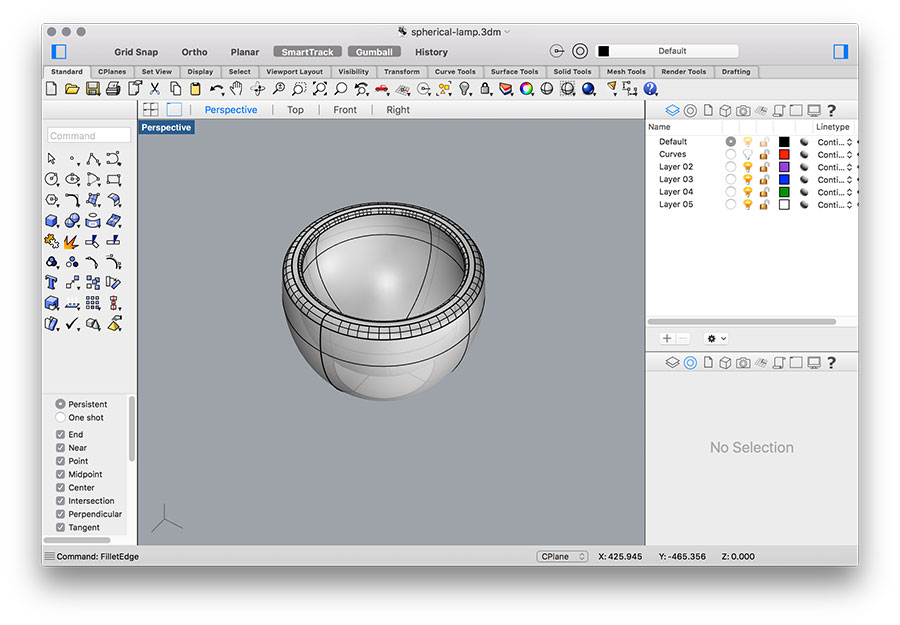
- Use "FilletEdge" on inner curve (on top) with smaller radius.
- Use "FilletEdge" on outer curve (on top) with bigger radius.
- Export as .obj.
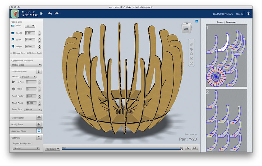
- Open 123D Make
- Settings: First, you have to set the sizes of your material (I used custom format so set the material size for our laser cutter 100x60 cm; 0,66cm material thickness). Then, set the dimensions of the object you like to make. As construction technique I have choosen "Interlocked Slices". Set your preferences in 'Slice Distribution'. You may also want to play with the rest of parameters until you have the design you like.
Download
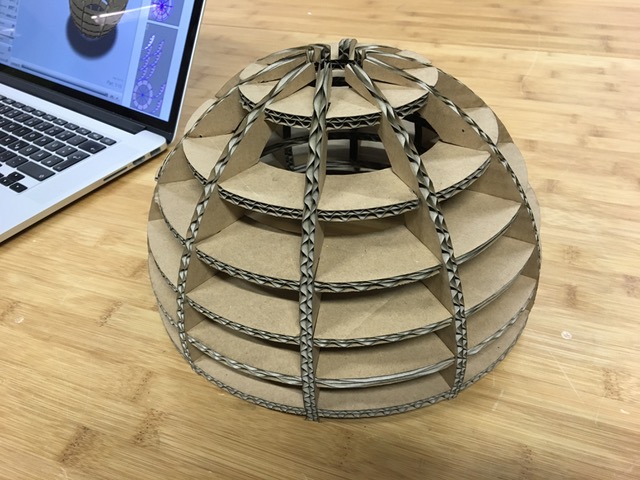
Another press-fit lamp
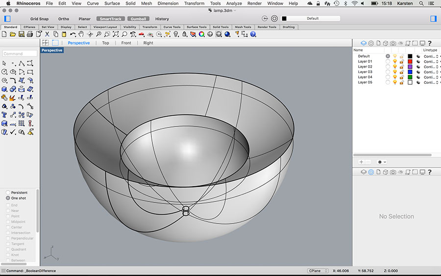
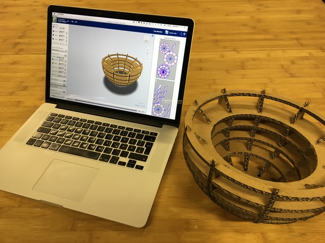
In Rhino I created a sphere, subtracted (boolean difference) a second and third sphere to concave the object. Finally, I subtracted a cylinder (for the cable fairlead). 123D Make needs a solid object for slicing (horizontal & vertical).
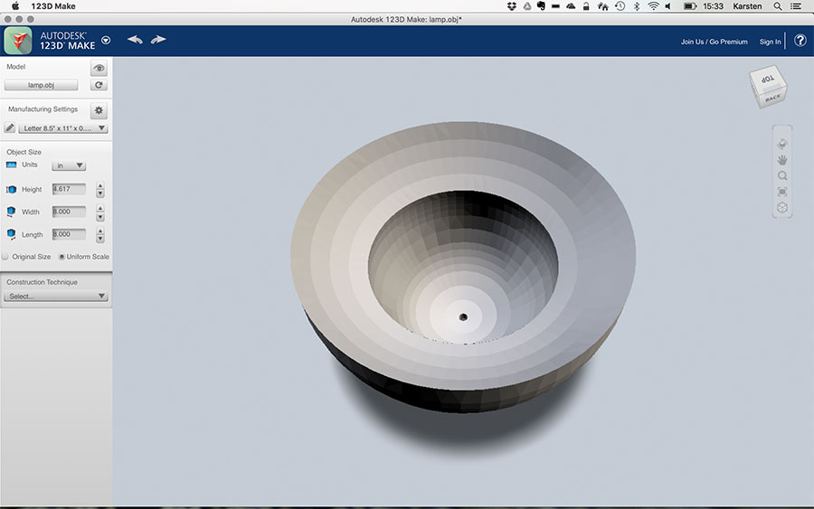
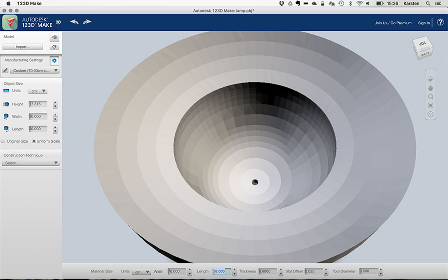
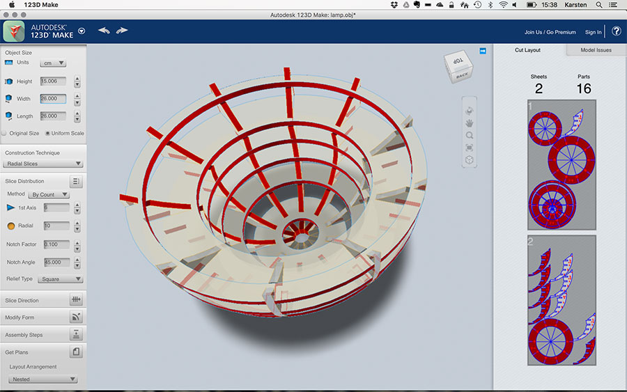
In 123D Design you first have to define the 'manufacturing settings' (i.e. material size, thickness, slot offset and tool diameter). After that you can select the 'construction technique'. I choose radial slices as my favour. The parameters enable to instantly manipulate the slice distribution, direction, etc. You will be surprised about the results and the shape you get.

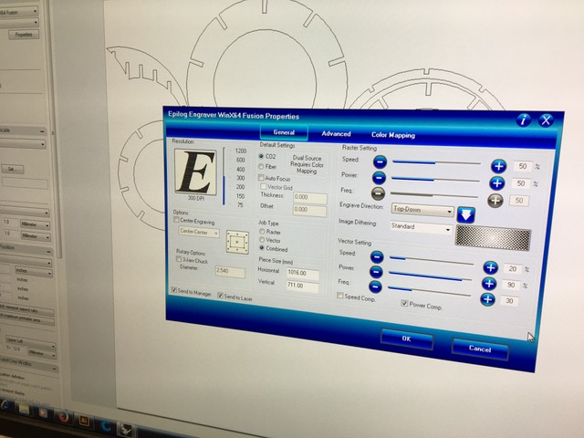
In principle, the laser cutted nicely (Speed: 20; Power: 90; Frequency: 30). But because the cardboard was not perfectly flat (it was cambering in the center), I had to complete a few spots manually, which was not a big deal, as the cuts have been almost through.
Assembly took less than 10 minutes.

Download
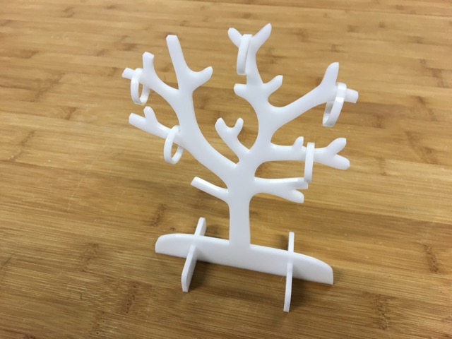
MAKE a press-fit jewelery Tree
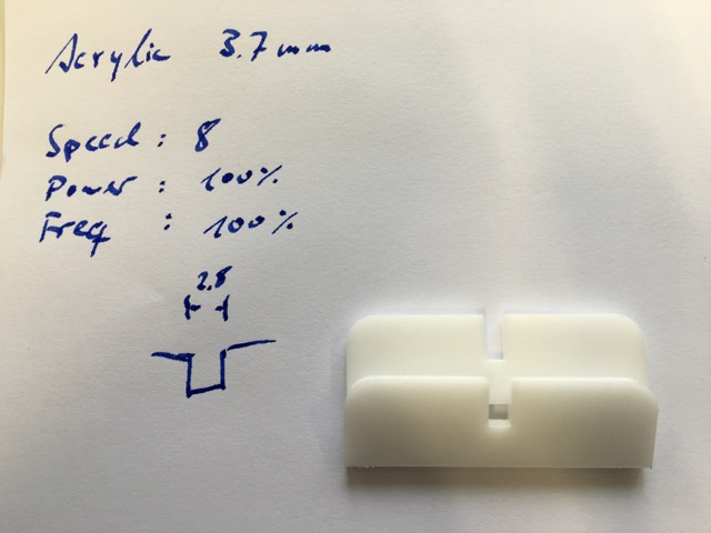
I used Adobe Illustrator in oder to draw a jewelery tree. I made two cutouts at the trees bottom and created two stands with cutouts, too. They should press-fit together at the end. For the material I choose 3.7mm white acrylic. Therefore I made the cutouts 3.7mm wide.

I made some simple cuts in order to find the appropriate parameters for the laser. This was quite easy, so I started to cut all the parts. However, while assembling them it turned out, that the cut of the laser was too thick. As a consequence, the stand was quite wiggly.
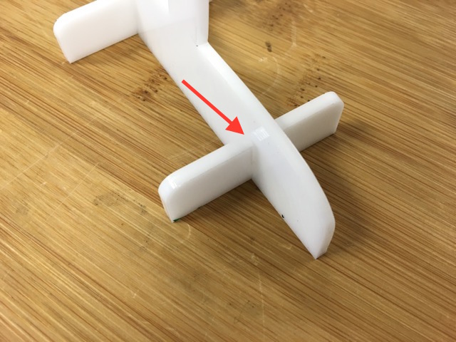
Thus, I had to find the proper sizes for the cutouts - as 3.7mm did not work.
Finally, 2.8mm fits. Thus, the cut of the laser (with the given parameters) has a thickness of 0.45mm.
At the end, the jewelery tree fits together and my niece liked it. I also made her some rings out of acrylic, too.
Download
Additional laser-cut/engraving projects
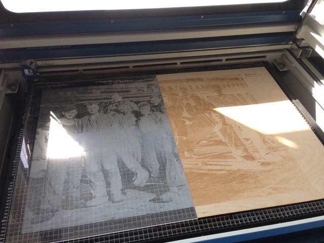
The following picture shows a group of coal-miners. Here a a photography was rasterized for engraving on acrylic and wood. The two materials were put next to each other onto the work space. For the engraving I used the same parameters.
We (Adriana, Luiz and I) also made businesscards using a simple sheet of gray paper. While engraving, the top layer disappeared and the brown-coloured core became visible.

2D Parametric Design - using Fusion 360
In the previous case I did a spaceship using 123D Maker and Illustrator to generate a 3 dimensional model. This time, I wanted to study more the construction of joints. I checked some references for joints and also you can visit this article in the Maker Magazine which presents different kind of joints:
-
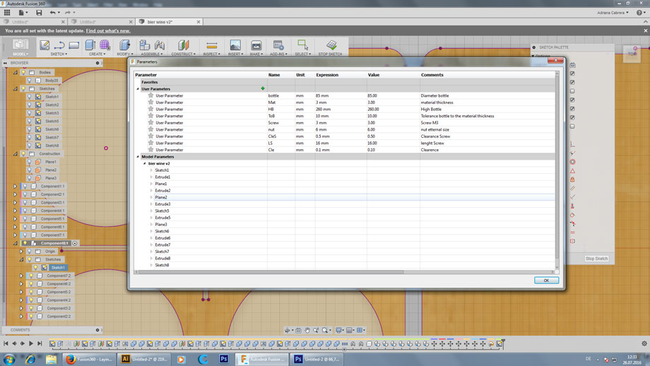
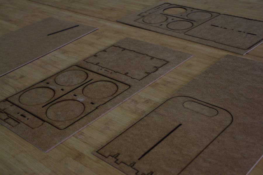
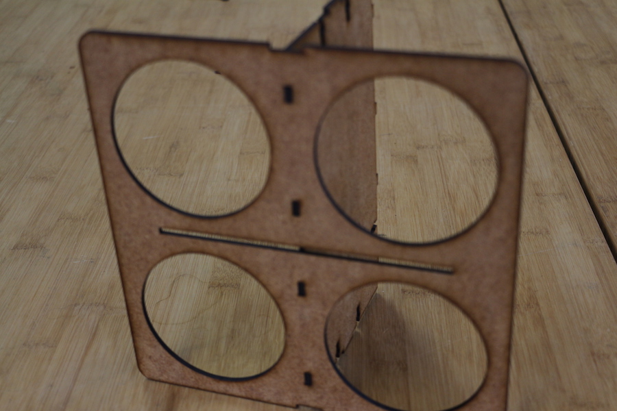
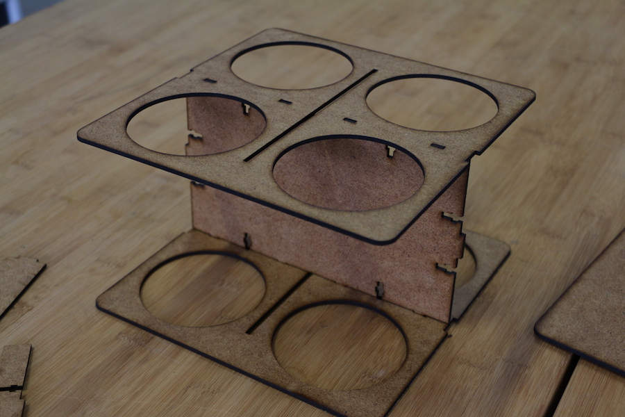
This task has an objective to experiment with joints in a parametric form. I selected a bottle holder, in order to create a model that I can generate parametrically for the following features:
- Work from a 3D sketch to generate a 3D body
- Increase the number of bottles
- Changing the diameter and the length of the bottles
- Change the material thickness, in fact the joints will modify parametrically
- Change of the clearance of the joints
- Change the diameter and length of the screws
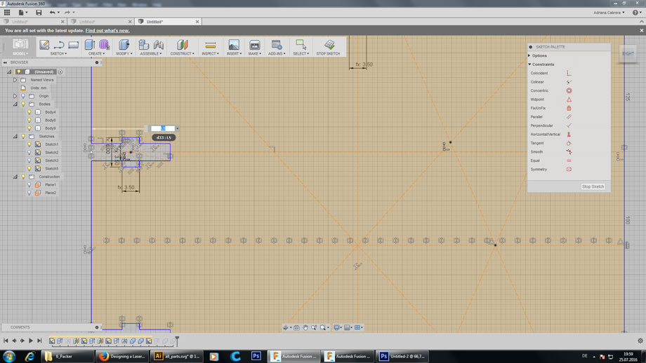
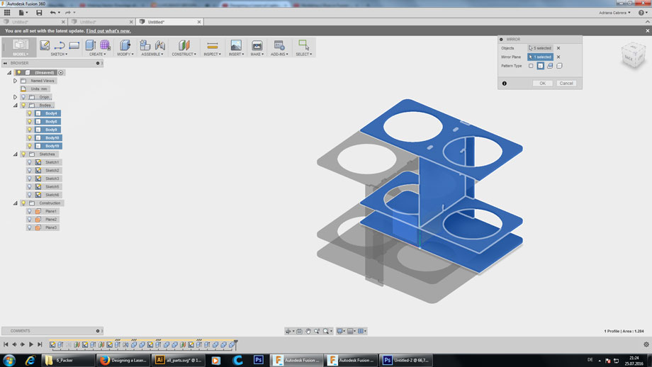
I began with the construction of a sketch from one bottle, thinking in the diameter and tolerance between each bottle. After it, I extruded the first three surfaces.

IMPORTANT: When your are doing a mirrored model, generating the whole model, you may work with the origin point and the origin point planes, in order to orient the symmetries in the same origin.
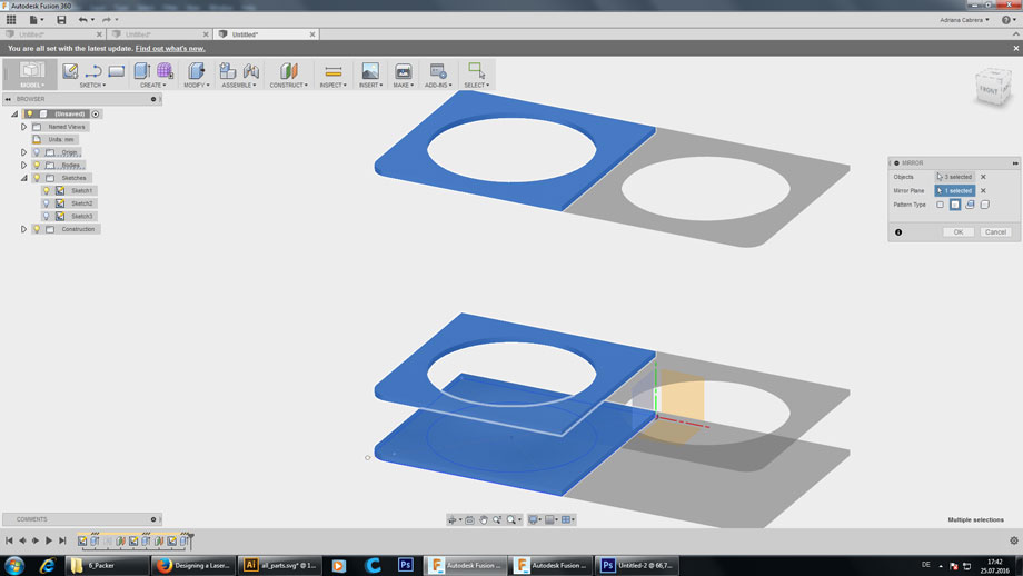
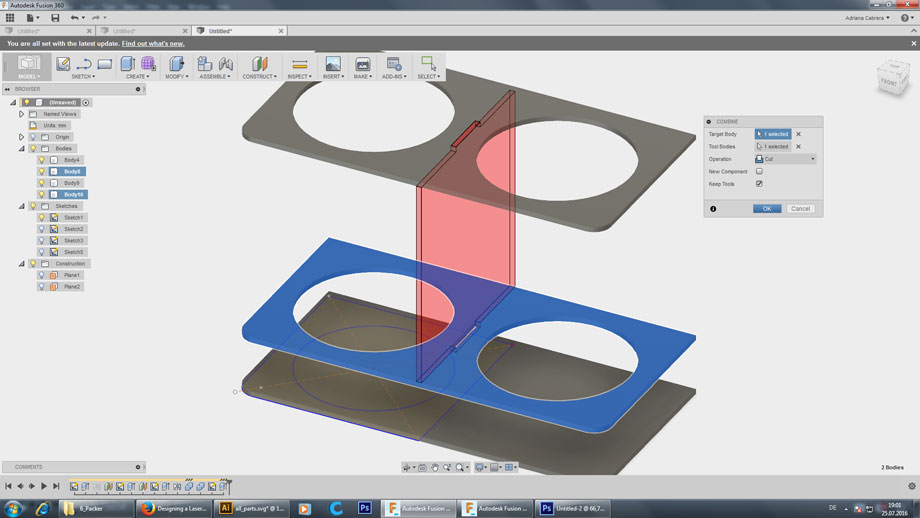
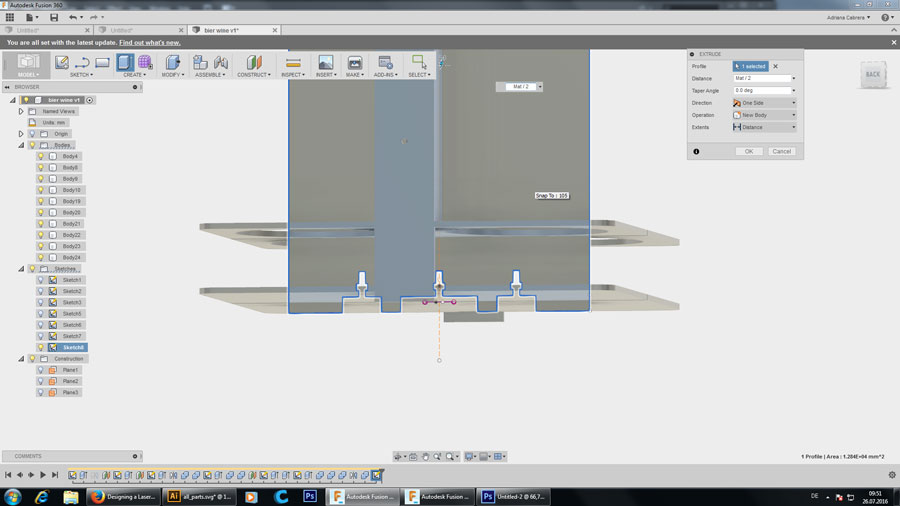
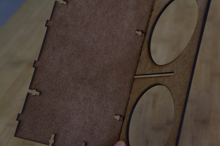
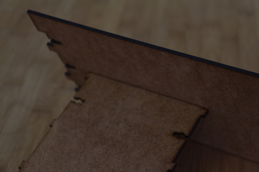
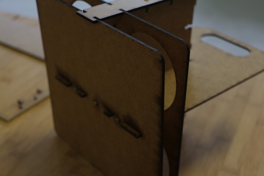
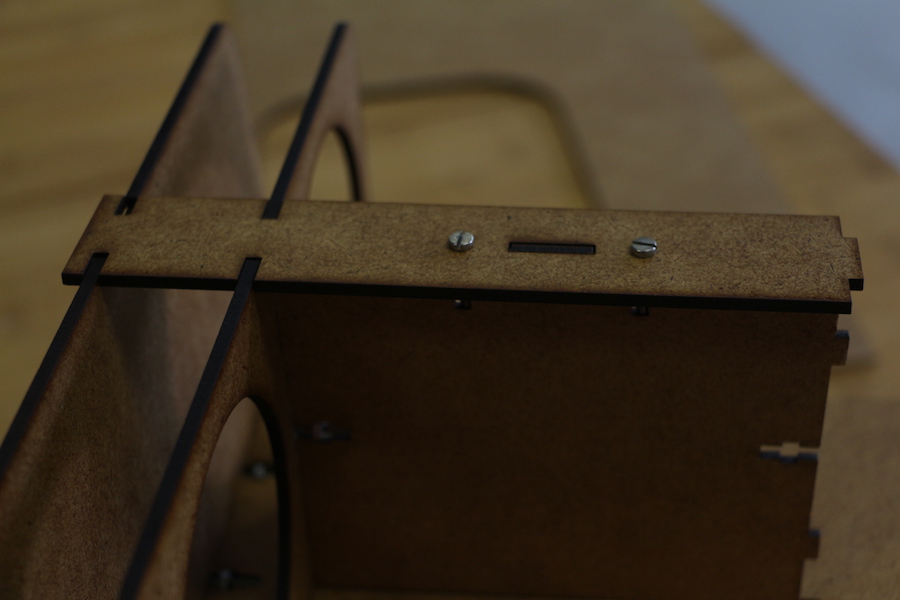
I proceeded to mirror the second part of the bottles, and join it using a boolean operation. You can find it in 360 Fusion in the panel: Modify> Combine > choose Join. Afterwards, I did a perpendicular support in between the three sheets, for this I designed a screw joint using two tabs and an extra tab for the external part of the joint. The extrusion of this part is in the origin. In order to conserve the symmetry, you can extrude the object using a symmetry factor, in this case I used the parameter “Mat” (Material Thickness) / 2. When generating this part you can see that there is an intersection of two bodies solved using a boolean operation. In this time instead of using a joint I used the CUT tool, IMPORTANT: If you are using cut option in the boolean operations, don’t forget to click the option: “keep tool”, for keeping both bodies.


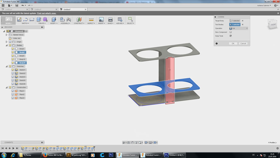
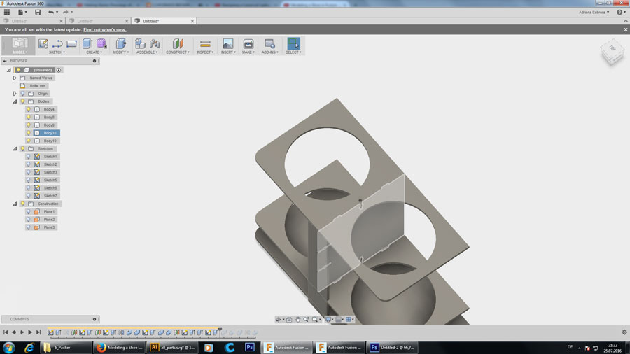
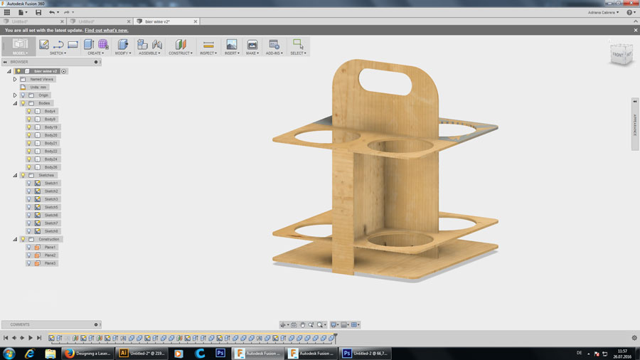
The final part of the model is the design of the holder, generating the legs and also the intersection of the other support. There is no clearance in the intersection. I considered a clearance only in the screws joints of 0,5 mm.


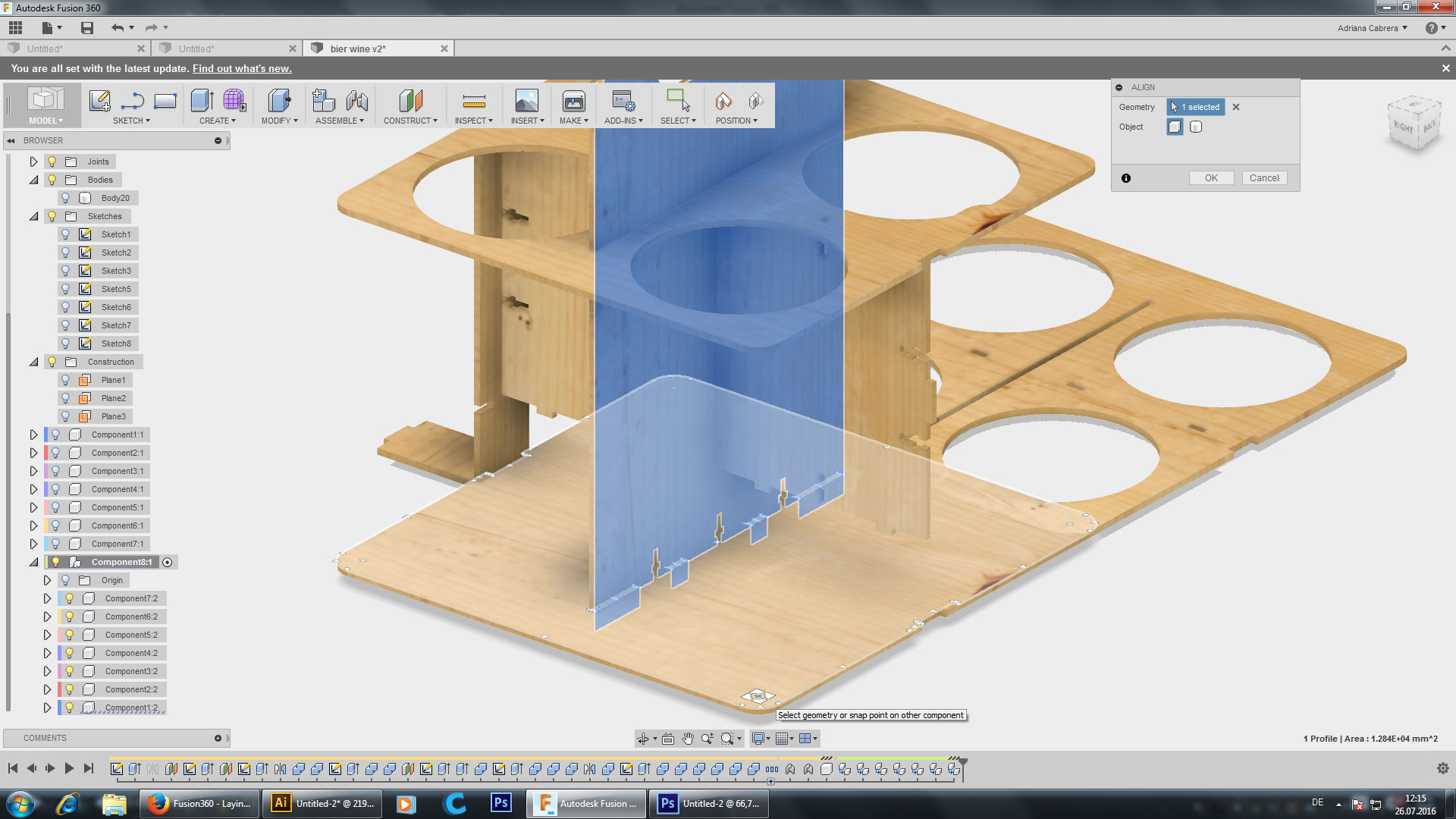
To generate a sketch for all the parts, I made a flat of all the components using the tool Align and moving all the pieces in the same top origin plane.
I did a new sketch to project the sketch of the bodies. Finally, I exported it in DXF format, in order to have the vectors and cut it in the Illustrator program, which is the compatible program for our laser cutter EPILOG FUSION.

When opening this data in illustrator, you can see that the lines are “exploded”, which means you have to join it in order to have a nice contour.
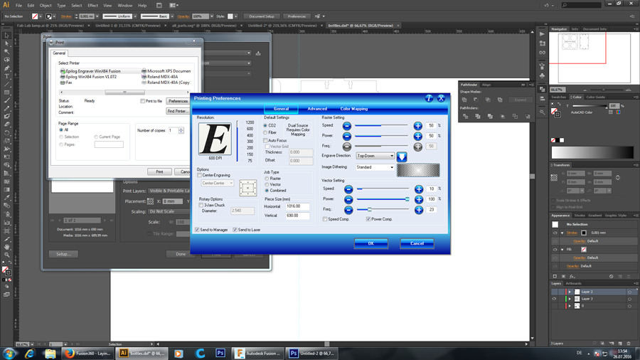
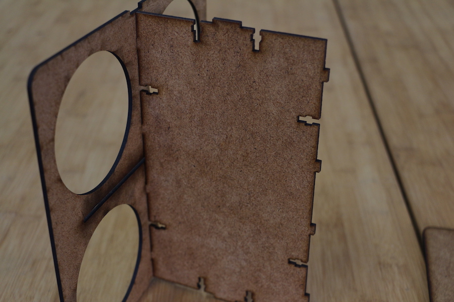
I did a test of the joints, in order to verify, if there is a need for clearance between the joints. I worked with MDF 3mm this time, giving more stability and durability to the model. I didn't have the need to use chamfers for my model.
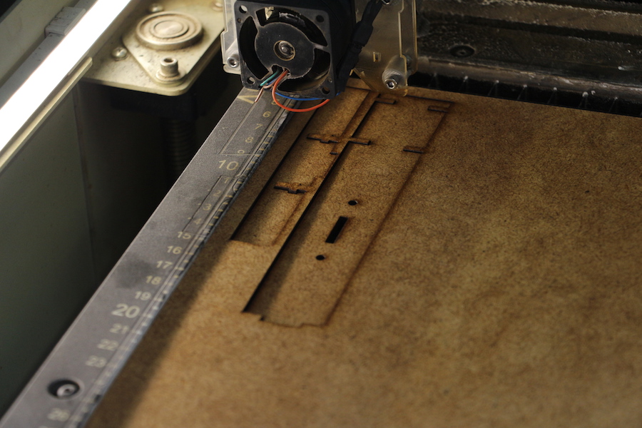

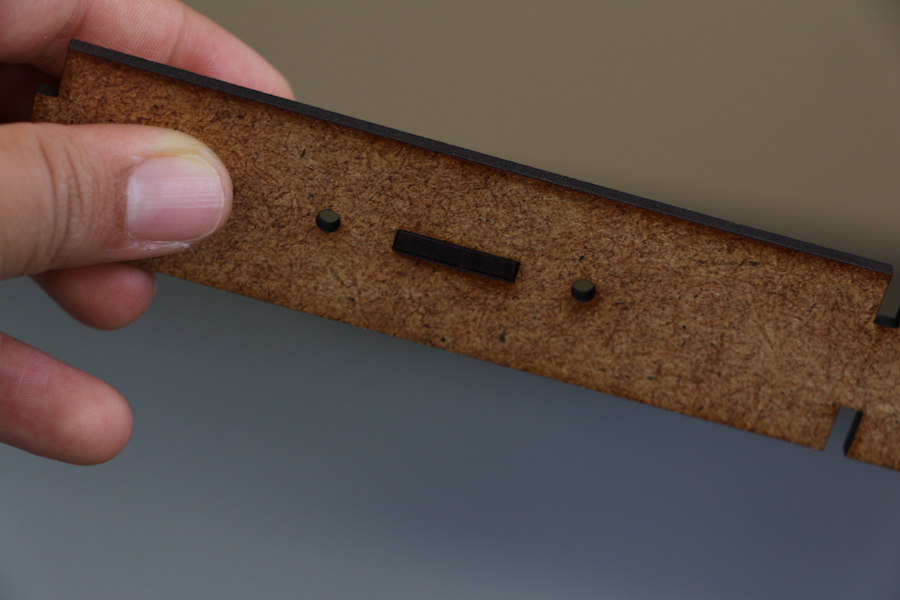
After it, I proceeded to cut the whole model in the laser cutter using 8% Speed, 100% Power and 20% Frequence. I had an error in the generation of the body of the holder because I didn't consider the taps in the bottom and the top part. In this case, I should enlarge this joint 5 mm.


Here you can also see a video of the laser cutter working: