Creating Something Big with The CNC Router
Document the process for CNC Machining
Make something BIG.
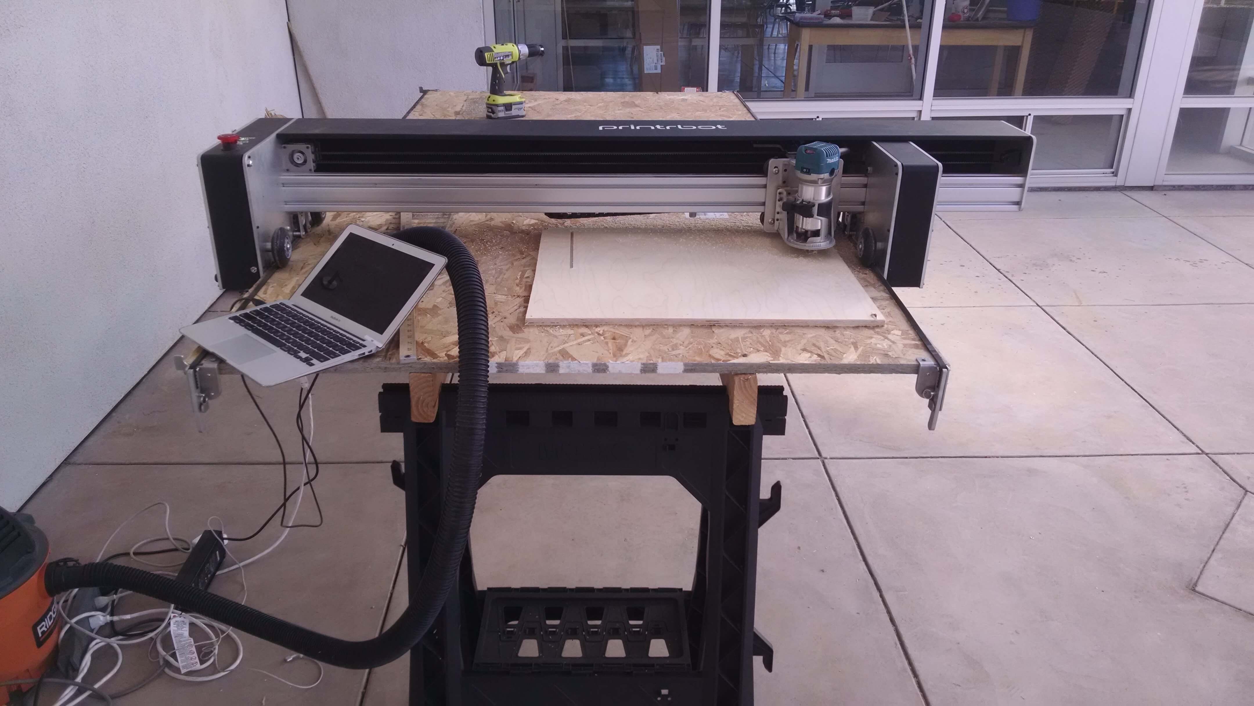
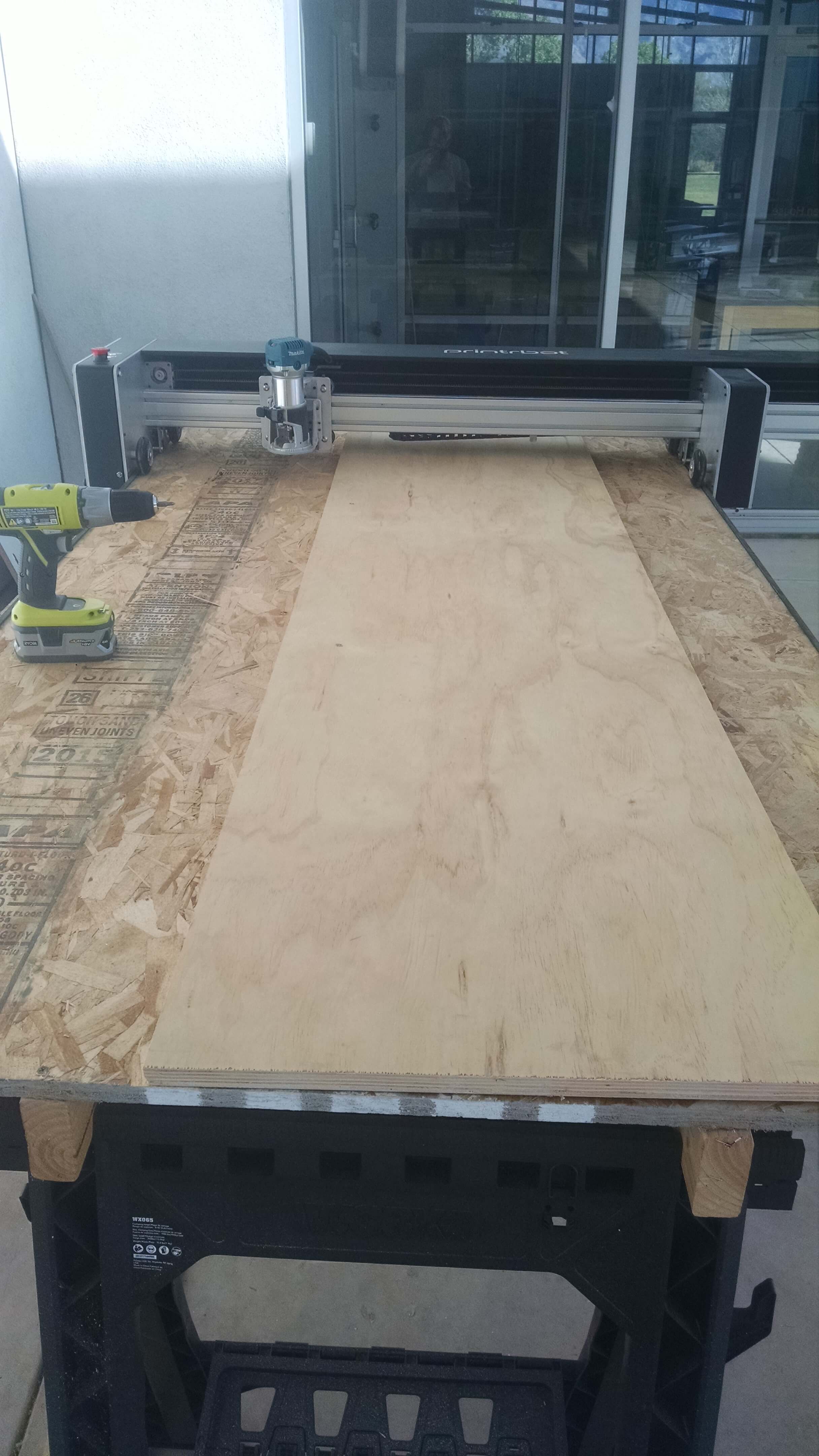
The CNC machine that I am using is a PrintRBot Crawlbot. The Crawlbot can cut
a piece of 4 x 8 plywood(or similiar) material. The Crawlbot is portable which requires setting up.
The setup is a pair of saw horses and two 2x4's. A base piece of plywood is placed down on the
2x4. The belt of the machine is bolted across the board and goes. The plywood for cutting is then screwed down
to the lower plywood. The machine is connected to the power and the computer. The computer sends the gcode to the
router and then we have our piece.
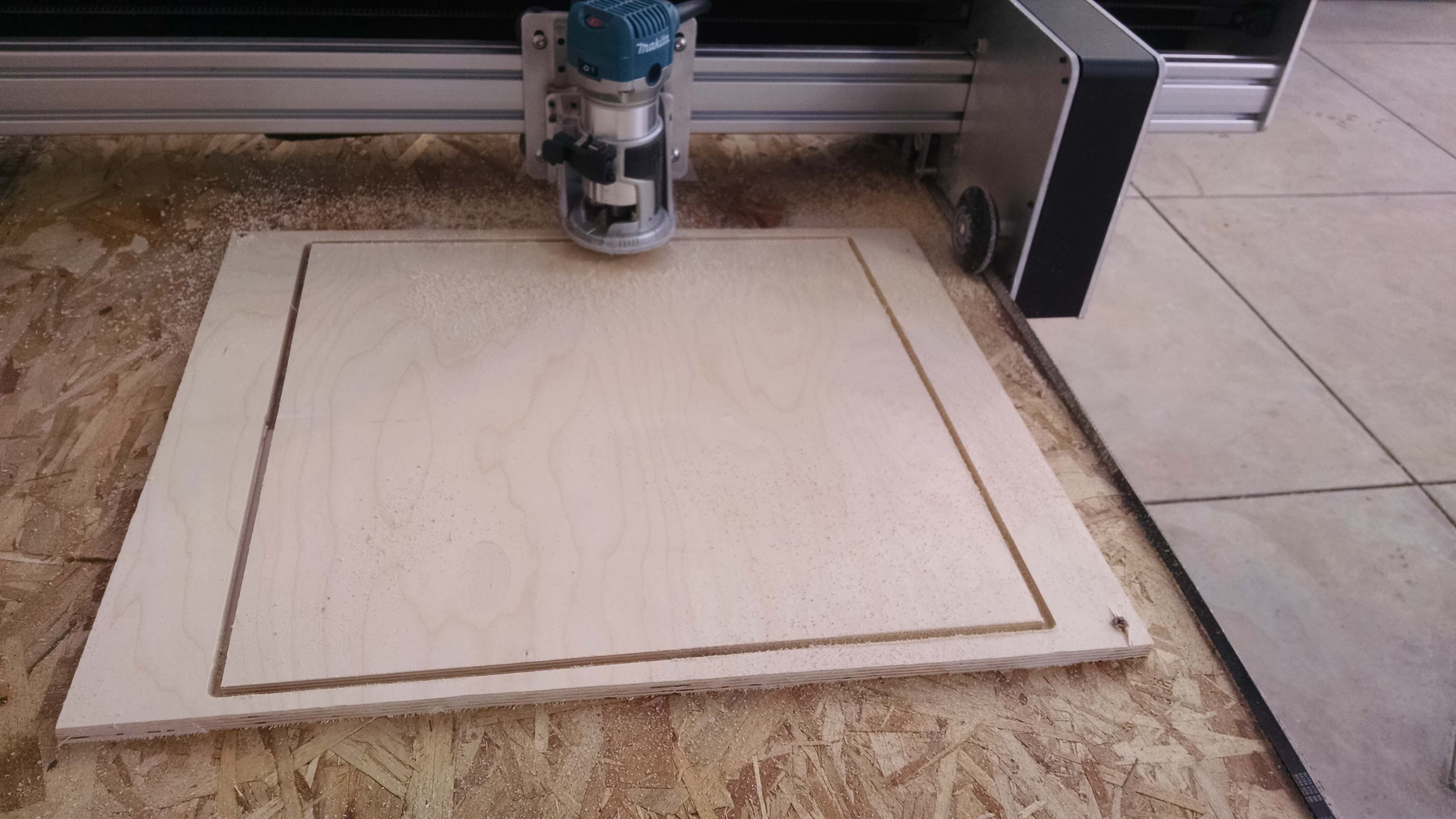
Test Cuts/ Design Rules
Two pieces were cut as test pieces:
1) A circle
2) A square
The circle was cut at 23.5". Within the margin of error of finding the diameter, it was exactly 23.5".
The square was 18.5" x 18 15/16". It too was within a 1/16th of an inch in accuracy(i.e to the precision to which I can rad
the tape measure."

The setup is about 5 minutes.
The machine requires GCODE, I will use Fusion 360 to generate.
The router bit can be changed to fit your need.
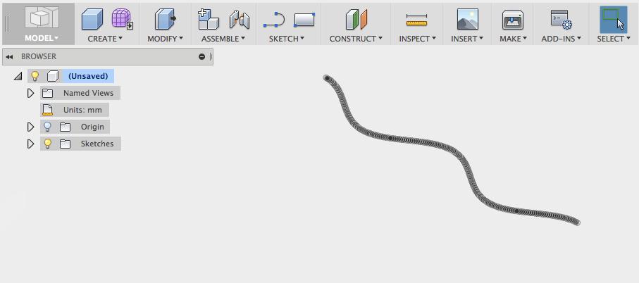
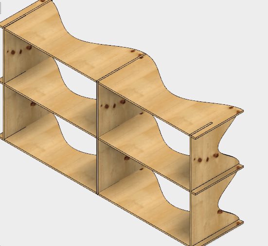
Building a Shelf
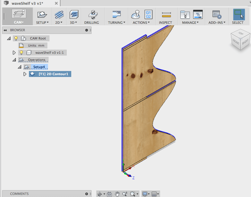
- Fusion Process:
- Select the piece to cut from Fusion.
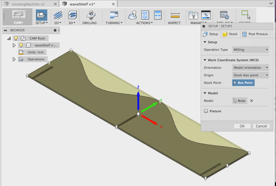
- Switch to CAM mode
- Setup the axis under setup. Proper X and Y axis is essential for cutting.
- Select the type of cut(2D Contour). Select Toolhead and Cutting Depth.
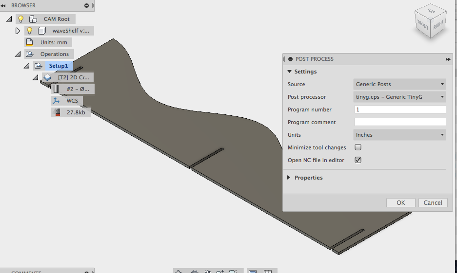
- Generate/Process the GCode.
-
Setup the Router following design rules.
Screw down the board to be cut to the wasteboard.
Open CNC App and set the origin of the system just as it was in Fusion setup.
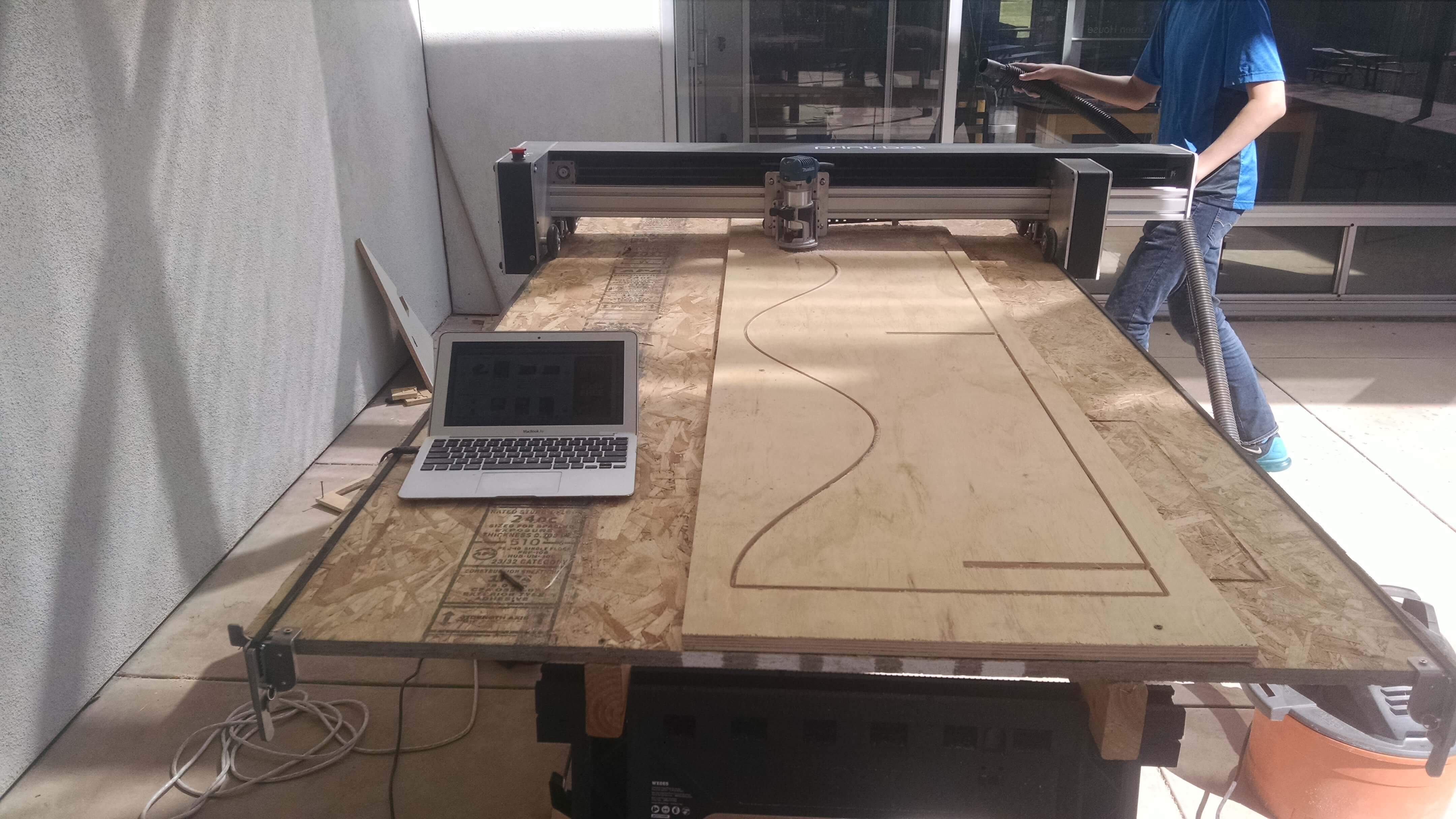
- Run the Code. Wait.

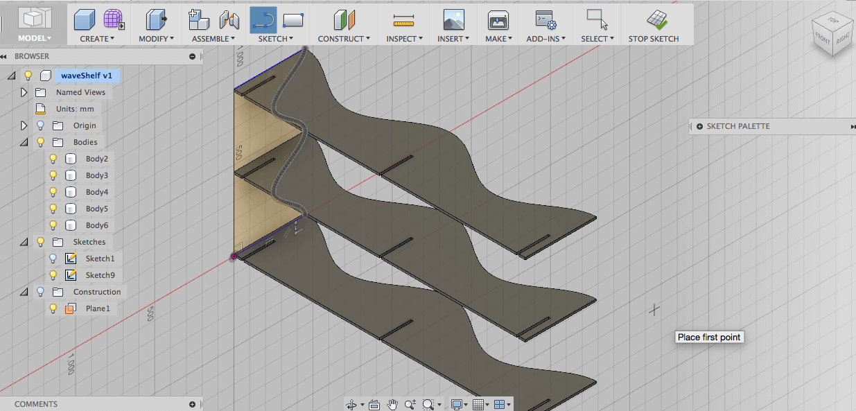
- Cut 3 Vertical and 3 Horizontal shelfs.
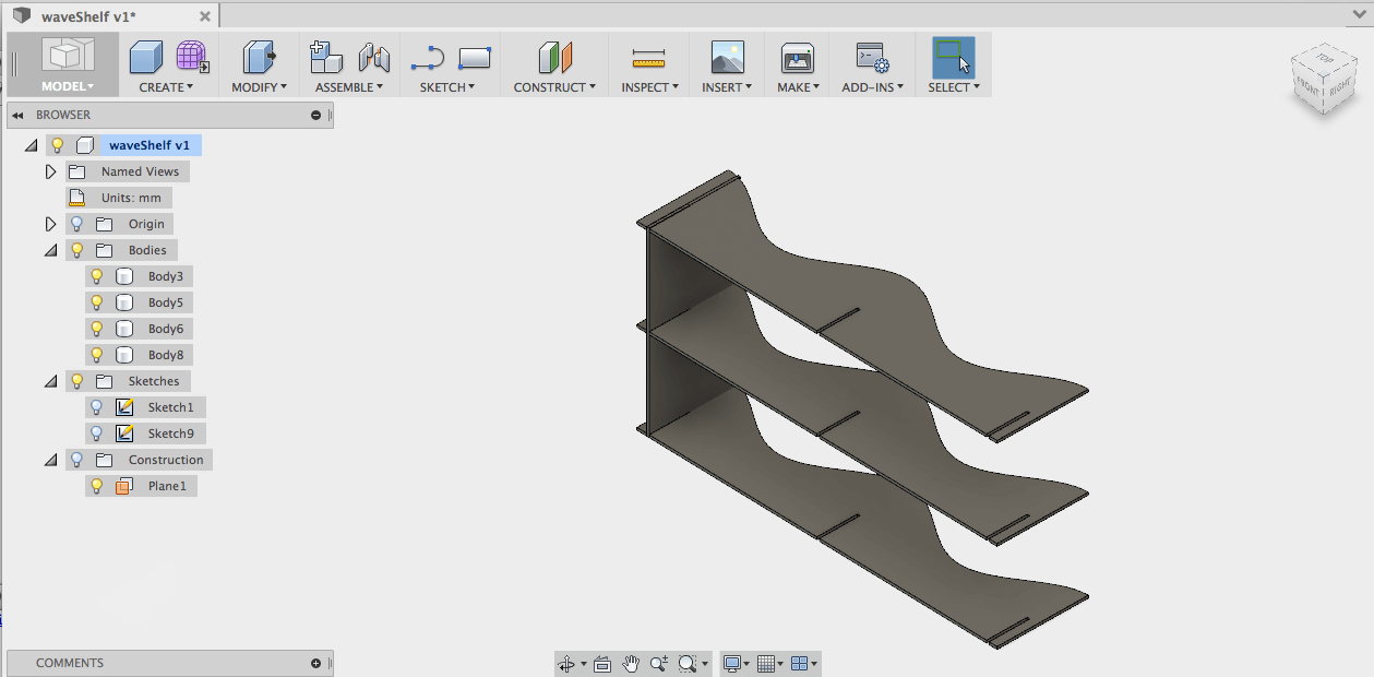
Mockup the position of boards.
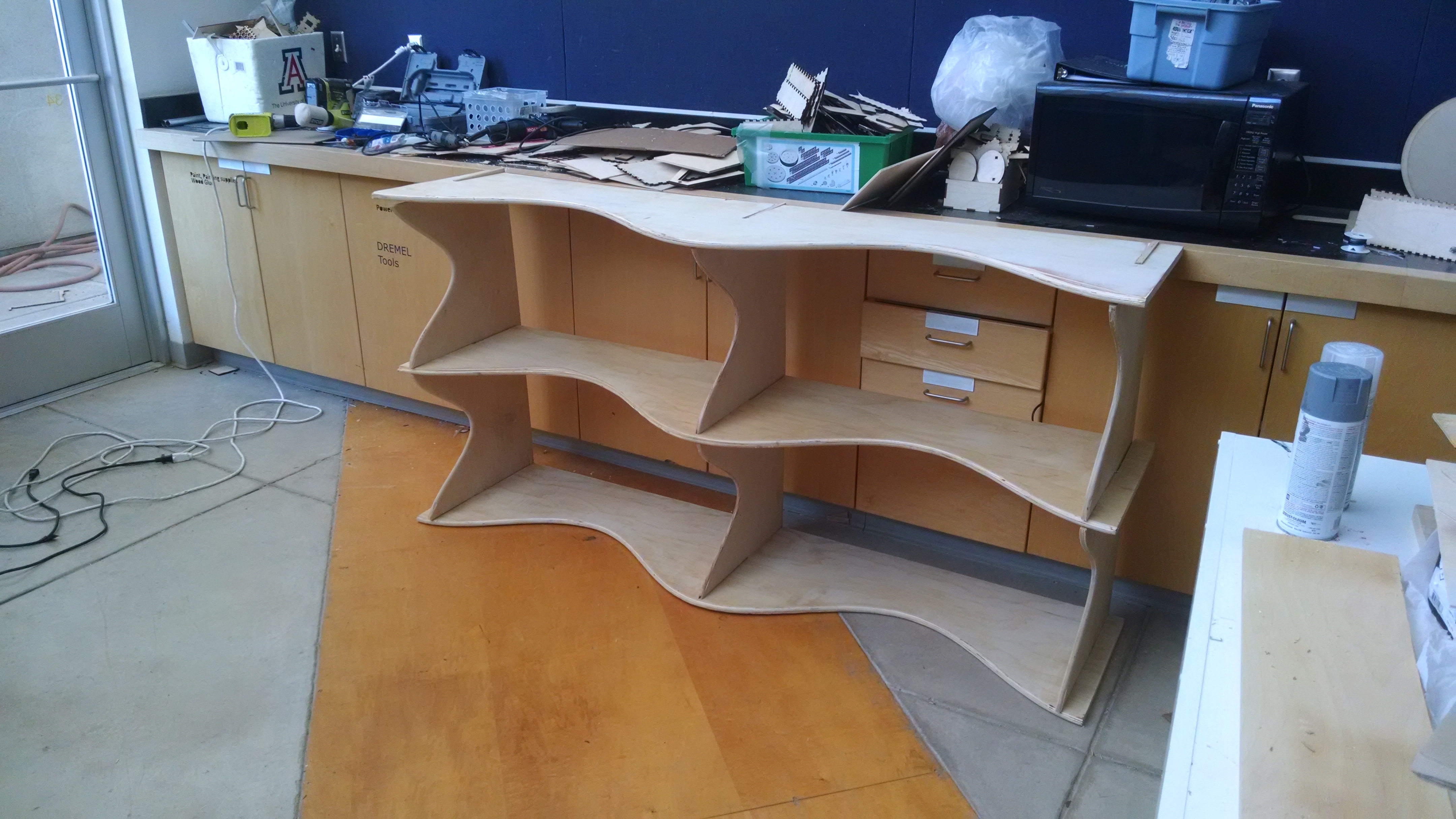
- After a little sanding. A Functional Shelf!
Lessons Learned:
My first cut, I forgot to lock down the wheel edge. This resulted in a misalignment on the second pass.
The depth seemed to be inconsistent. Some of this is from slight warping in the board. Some due to the
bed not being level.
After several pieces, the process is faster and very consistent.
The CAM tool
After using the CAM tool and CNC router for several projects throughout the class, I had numerous learning
lessons on getting the tool set right.
It is important to get the right speed.(I mistakenly choose a mill tool setting aimed at Aluminum once,
and it was way too slow.)
Here is the basics. It is pretty simple.
Switch from model view to CAM.
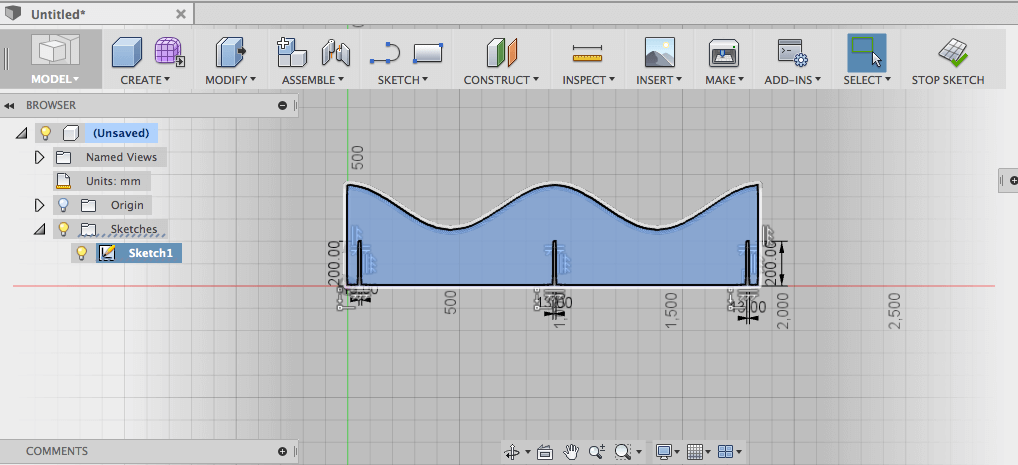
Choose setup. Position the axis where you want. The tool cuts in the XY plane. Ensure
your contour is in the XY plane. Clicking the arrows changes the direction.
Choose 2D-Contour. Click on the bottom edge of the piece.
In the dialoge box, check the settings. I made a new 1/4" tool and choose the RPM to be 5000.
Changing this changed the speed. When cutting, my tool cut about 1m per minute. I could adjust the
RPM to make it cover more. Also need to check the speed of the router. You can increase the speed, on the knob.
The spindle speed is not controlled by the program.
Click OK on the diaglog. Select Post-Process. Coose Generic TinyG. Your G-Code is generated.
I inspected the code with Brackets to make sure the dimenstions made physical since.
I opened Printrbot App from chrome. I positioned the router in the same location that
I instructed CAM tool. At this point, I zeroed the axis. Because of fluctuations in size.
The depth of the machine is another issue. I zero the machine at the top of the board. I prefer to make
my model larger(more depth) than the actualpiece of board. Due to warping and variations, if I cut straight
there tends to be about 10% not cut through. I fix this several ways.
1.)Instructing the board to cut
deeper, by making the wood thickness greater. Some of the cut is into my wasteboard, but that is what its for.
2.)Setting the z-axis zero in the wood.(About 0.1" below on a 0.75" board.)
3.)After finishing the contour, it is easy to see whether or not the cut completed.
Run the contour again, but manually move the router position to cut into the wasteboard.