My first attempt at doing this I was able to communicate witht the module. It is pretty easily. However, the board
was stuck in this mode where it was sending me information. After a little research, this was not normal.
After a while, I could no longer send commands.
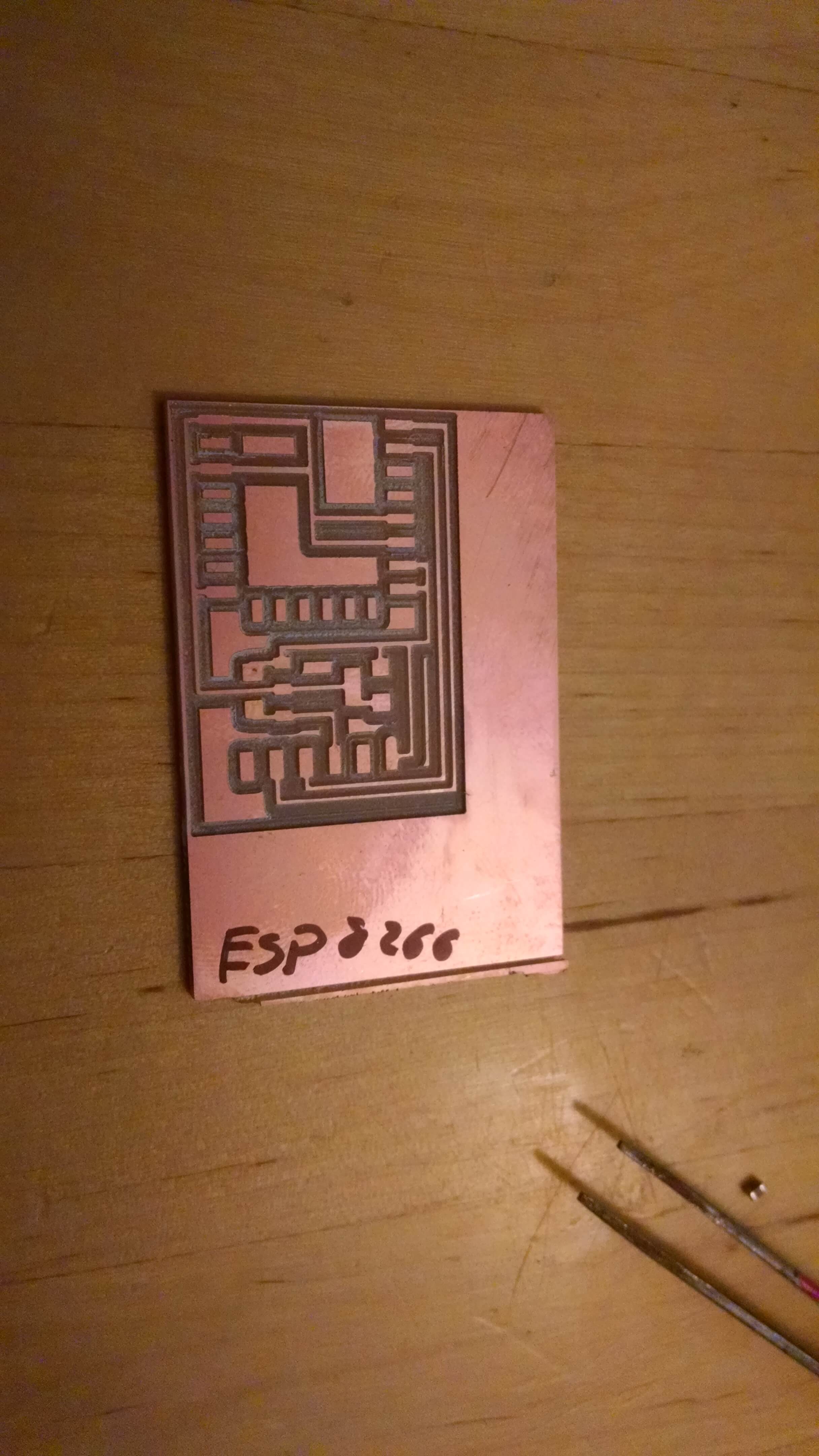
I decided to abandon this board and start over.
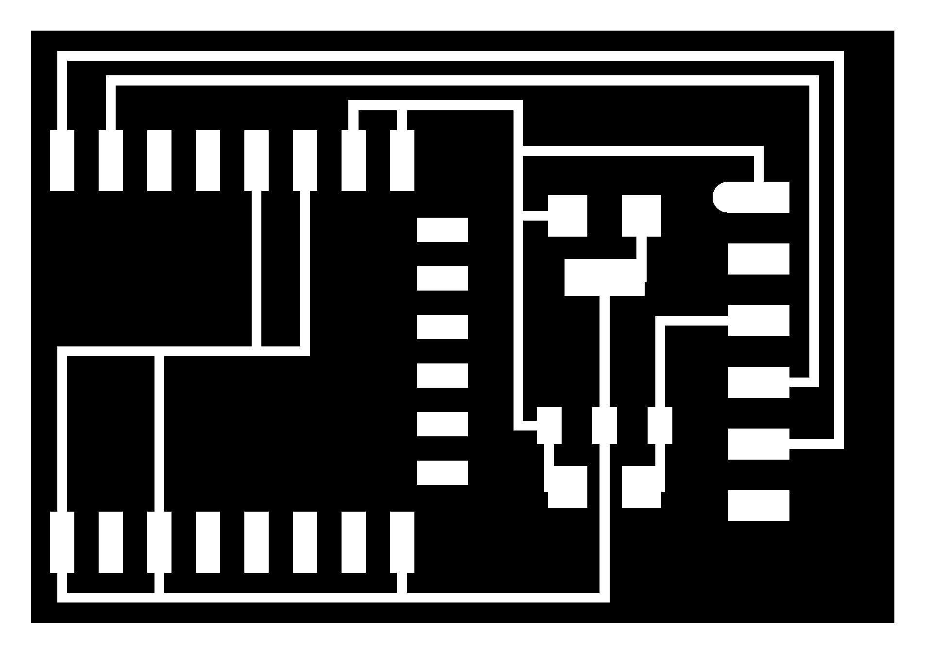
I used the same image to mill the board.
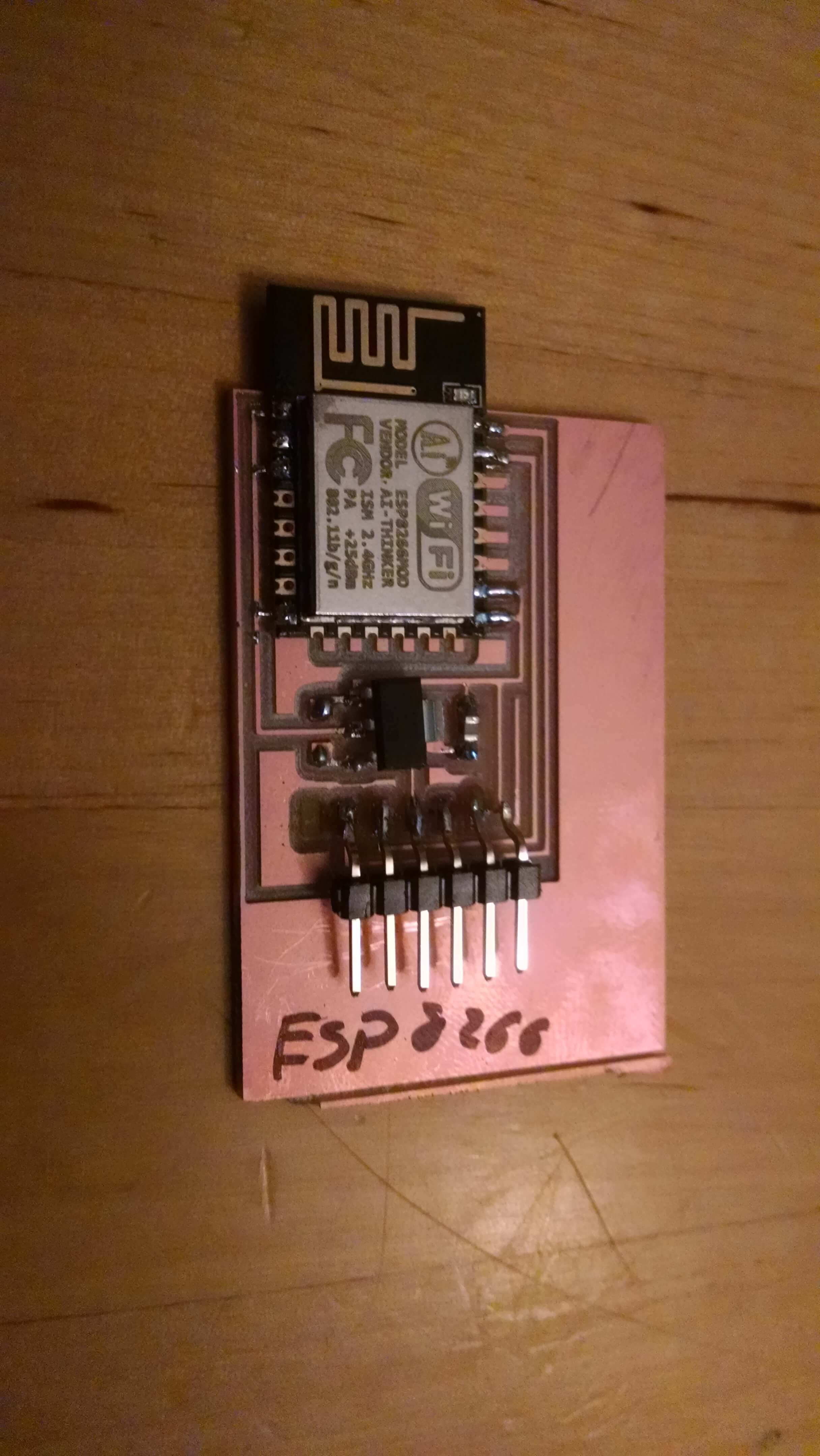
I re soldered all of the connections.
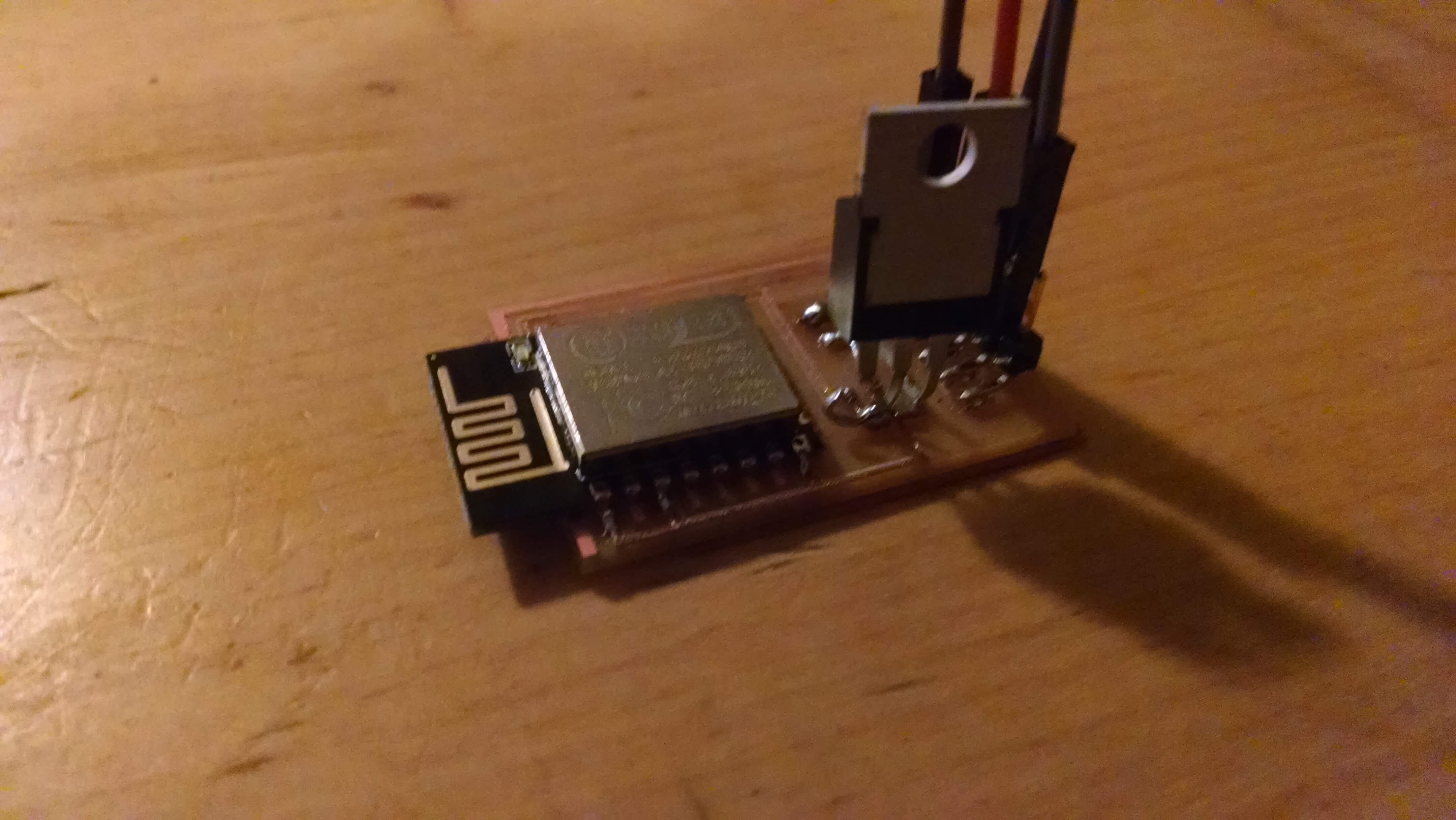
I could not find a SMD 3.3 V supply, so I switched. The pins had to be bent to fit the board.

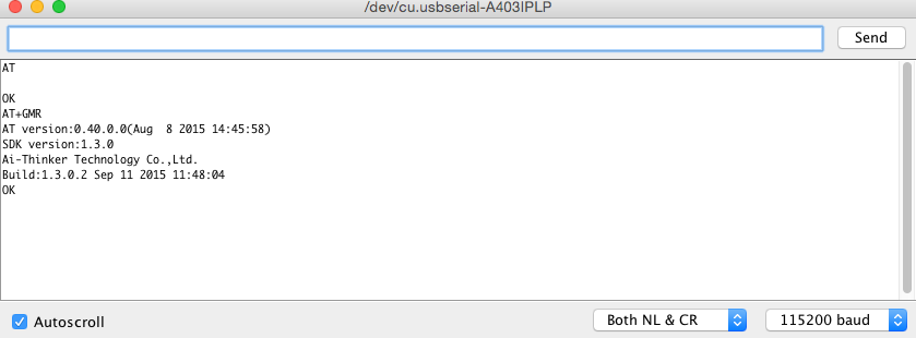
The new board worked great. Issuing AT, gives a OK response. AT+GMR returns the version and info on the board.
To issue commands I used the Arduino IDE. For me the Baud Rate was 115200. At the bottom, of the Serial Monitor is
an option to send commands with NL(newline) and CLR(Clear). Select that.
You can also send the commands with /n/r attached to the command.
The assignment is to connect two devices. It is trivial to have an arduino send the commands. Connect the serial
RX to the TX of the Arduino. The TX to RX. Ground and Power also connected. The Arduino can send the command and get
back the output.
I found these examples helpful:
Ray's Hobby
Room 15 ESP 8266
In the end I was able to get the board to act as a server and to fetch a simple webpage. I need
to work on either parsing a page and sending GET request to use on more projects.
When I get a second module to replace the one(I think I broke) I will play with pairing two of them.
My final project requires two arduino boards to be connected to one another. It is easy to do serial connections between
two boards. I wanted to try using the RS485 standard that was used in Machine Building tutorials.
I know it has a long range and can do multiple sites on the same line, but I want to learn more.
I have several RS-485 modules and want to get them connected.
In the future, I would like to add more info here on that.
I have two commercial RS-485 modules: MAX485/RS485 from Amazon.
I connected them with two commercial Arduino boards on different computers.
I ended up having to connect the ground between the two boards so they are not completely isolated.
Some tutorials have used Earth ground for both, but I had to have a common ground.
Here is the setup:
I followed this tutorial:
RS485 example
It worked fine. The boards easily sent an echo.
I need to experiment more with these, but they were easy to work with.
I need to try the multi-drop capability. I don't know if I would ever need to test distance, but
I would like to see a comparison vs the normal serial output.
Simple Serial Connections
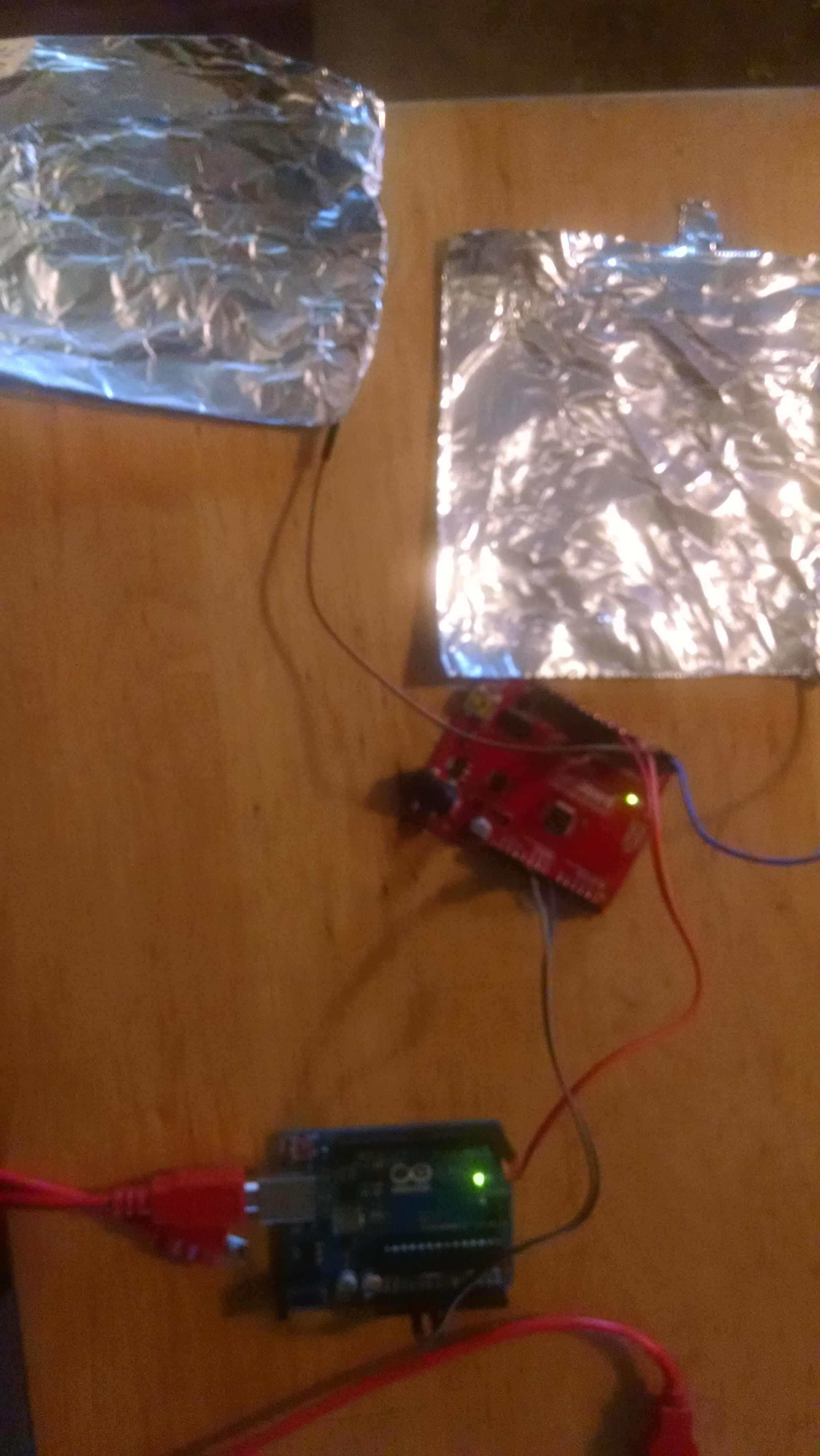
The excercise for Networking is to get two boards to communicate. I did this early in preparation of my final
project. I have one capacitance sensor sending serial data to a second board. That second board is going to collect
data. Here is the process of getting these two Arduino's talking. I will make a custom receiver board for the Final Project.
Upload the software to the sending board.
I am using Arduino and the simple capacitive sensor.
This is a simple network that I will incorporate into my final project.
Serial Out and Capacitive Sensor
Serial in and Blink
I uploaded Serial Out and Capacitor to one Arduino board.
I uploaded Serial In and Blink to the other.
I connected the Serial In to the computer so that I could monitor Serial and power boards.
The RX of Out Board(Pin7) goes to TX of other(Pin 2)
The TX of Out Board(Pin8) goes to RX of other(Pin 1)
The OUT Board relays data to the In board. The In board reads a value, converts it to an integer,
and then makes a decision to flash a light or not.
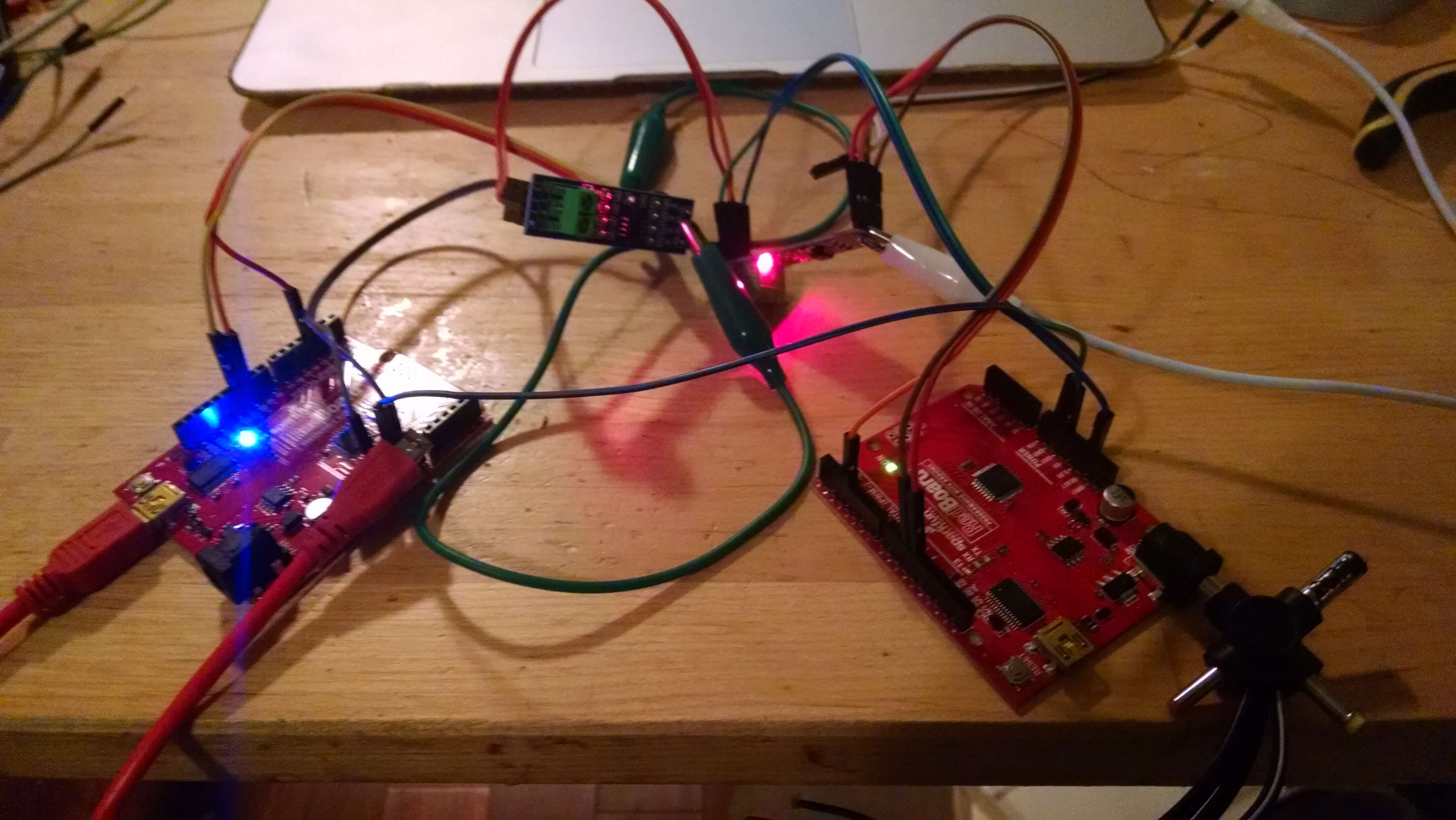
Working Boards: