Output Devices
The goal of this week is to make a device which has an output component on it.
Choosing an output device.
Designing the board.
Making and Inspecting the board.
Programming the board.
Choosing an output device.
Designing the board.
We are going to make a board using a attiny-45 and make a simple LED flasher.
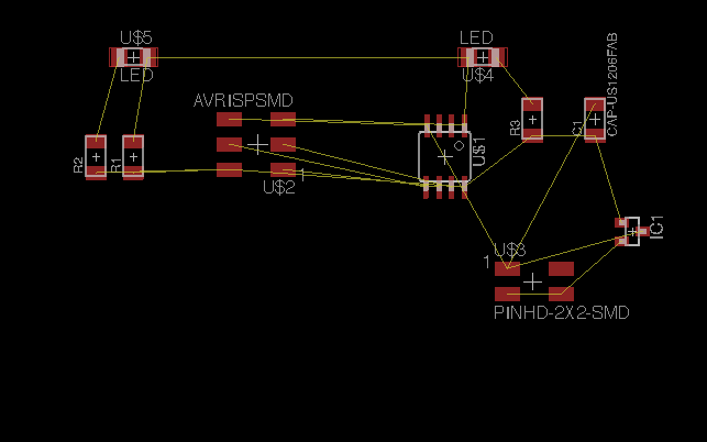
First, we add the components to the schematic.
Attiny-45 microprocessors
3x2 header pin for AVR cable.
2x2 header pin for power input
Capacitor for filtering input
Pull up resistor.
Resistors for LED
LEDs
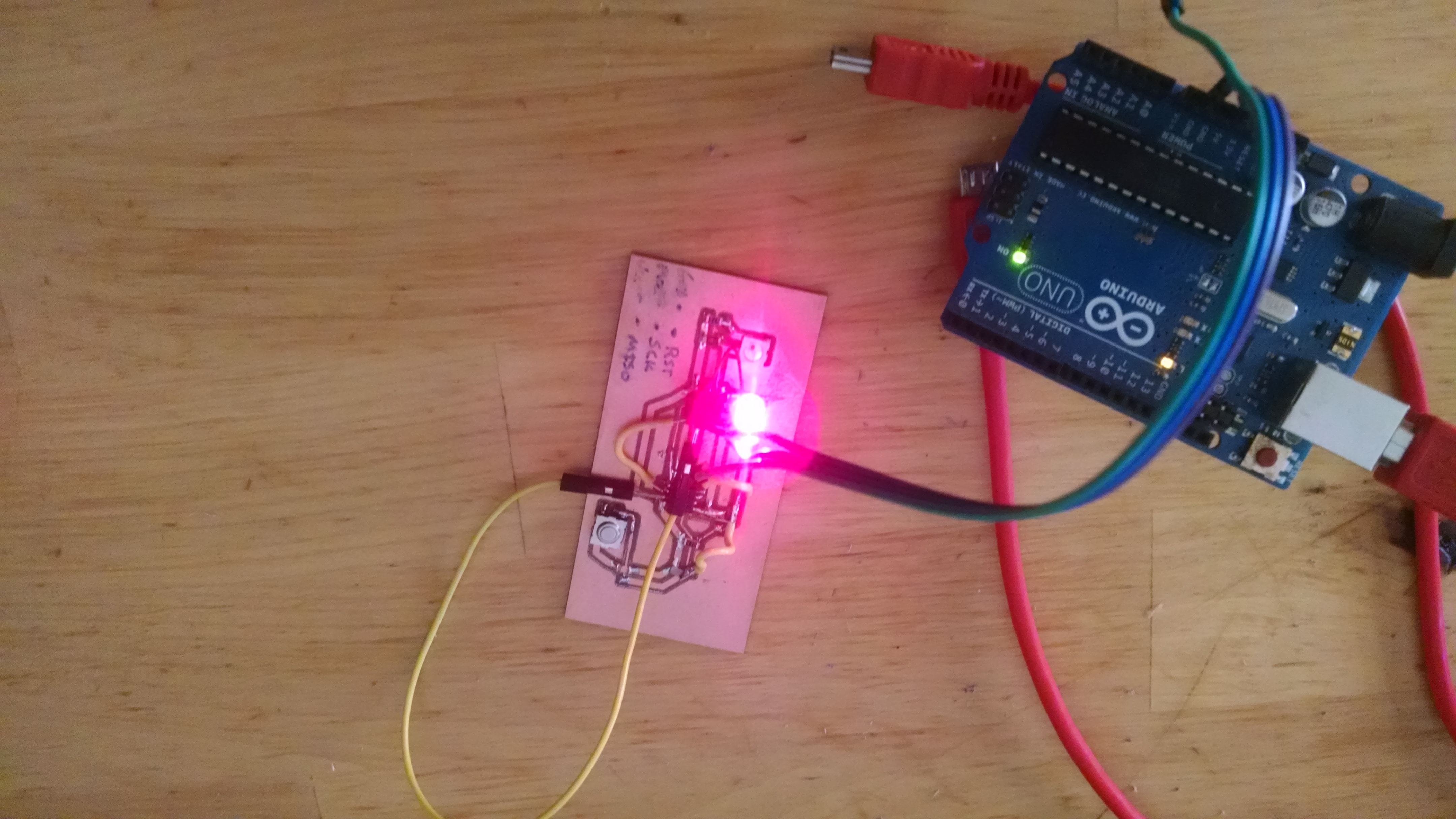
This example(the board not the program) is from Week 11(Input Devices). It is the Hello-Button. I used the board to flash the LED.
Process:
Generater an Eagle schematic layout with each of the parts.
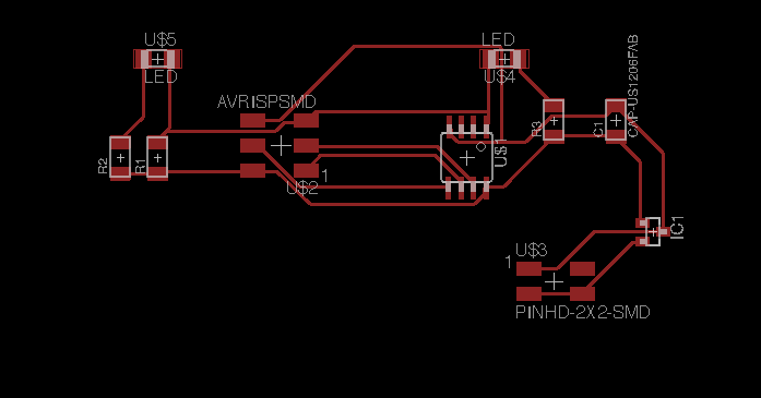
Create a board and position the elements where you want them.
Autoroute the routes. Delete and Reposition the wires as desired.
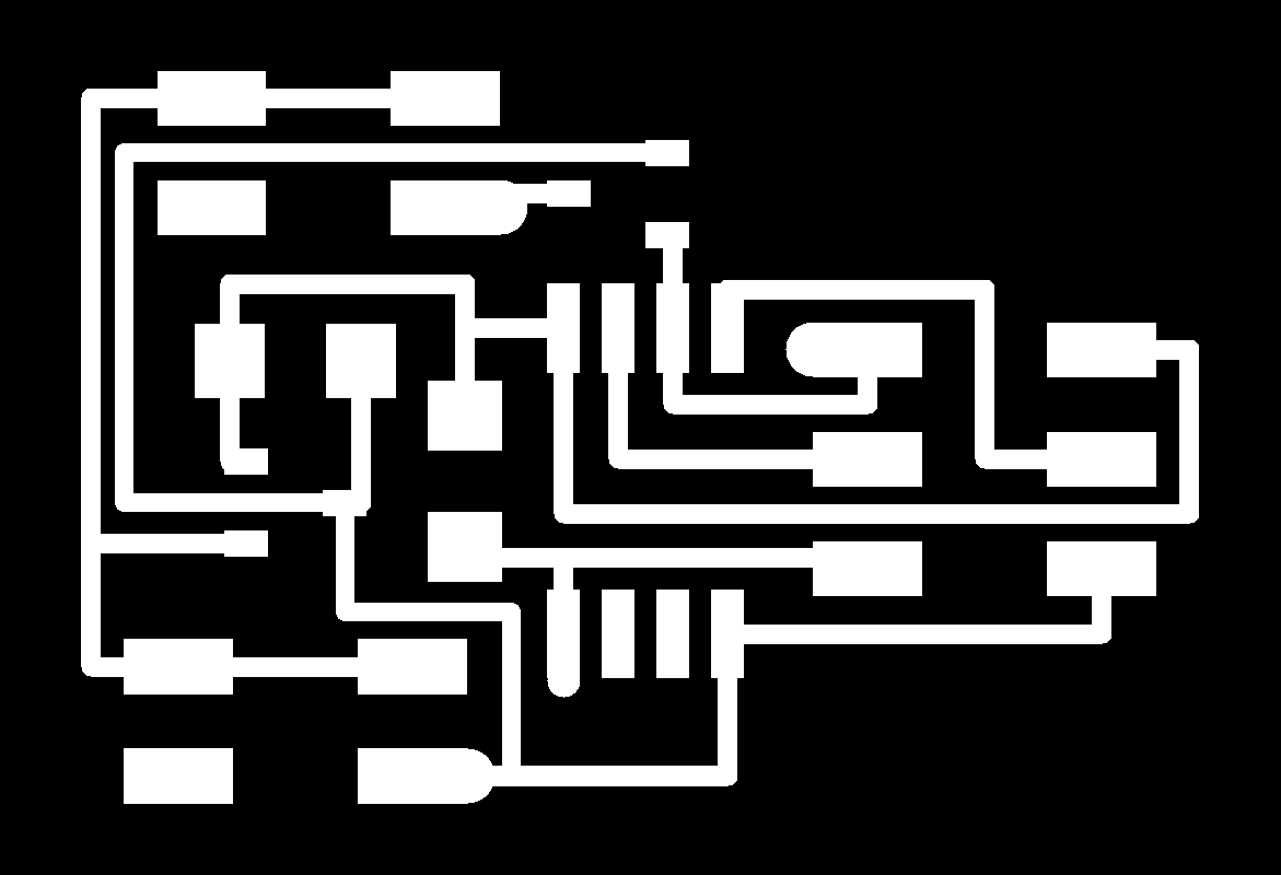
Export a monochrome png of the top layer.
Import PNG image to Fabmodules.
Generate GCode for the mill.
Edit the GCode for the machine and mill the board.
Check the connections with connectivity meter.
Solder the board.
Check connections with voltmeter/ohmmeter/capacitance meter/connectivity
Write the code.
Program the board.
Milling, Soldering, and Inspecting the board.
This process is the same as before. Milling was done on the CNC machine.
Each of the elements was soldered. The board was inspected using a connectivity detectore.
Programming the board
I used Arduino IDE for this board. I previously programmed this same board using C, so I switched.
The starting point for me is the example:
Blink
It is part of the IDE examples.
The Attiny 45 has 5 output pins.
3 pins are digital(Pin 2/PB3, Pin 3/PB4, Pin 7/PB2)
2 pins can be digital/analog output(Pin5/PB0 and Pin 6/PB1
If pins 5 and 6(i.e PB0 and PB1)are connected, you can use PWM. The
Fading Example is cool.
It would also be possible to run servo with those pins.
To use the blink example you need to make a change to the code.
Pin 13 is written for the Arduino Uno(ie Attiny 44) but with the 8 pin Attiny 45 that does not work.
Switching to pin 1 and playing with the delay gets us our first working output:
Again...
Repeating this with a 3 led board and a piezo.
The Attiny has 5 outputs. I thought I would use more of them on my second board.
I decided to start from an existing board, the example speaker board(Neil's hello.speaker.45) board.

The example uses PB1 to power a speaker. I want to add leds to this board. The speaker example uses a transistor
ic to power the speaker. My example here is just using a piezo, so I soldered the piezo to the PB1 and the Ground.
Soon I will desolder and add a speaker.
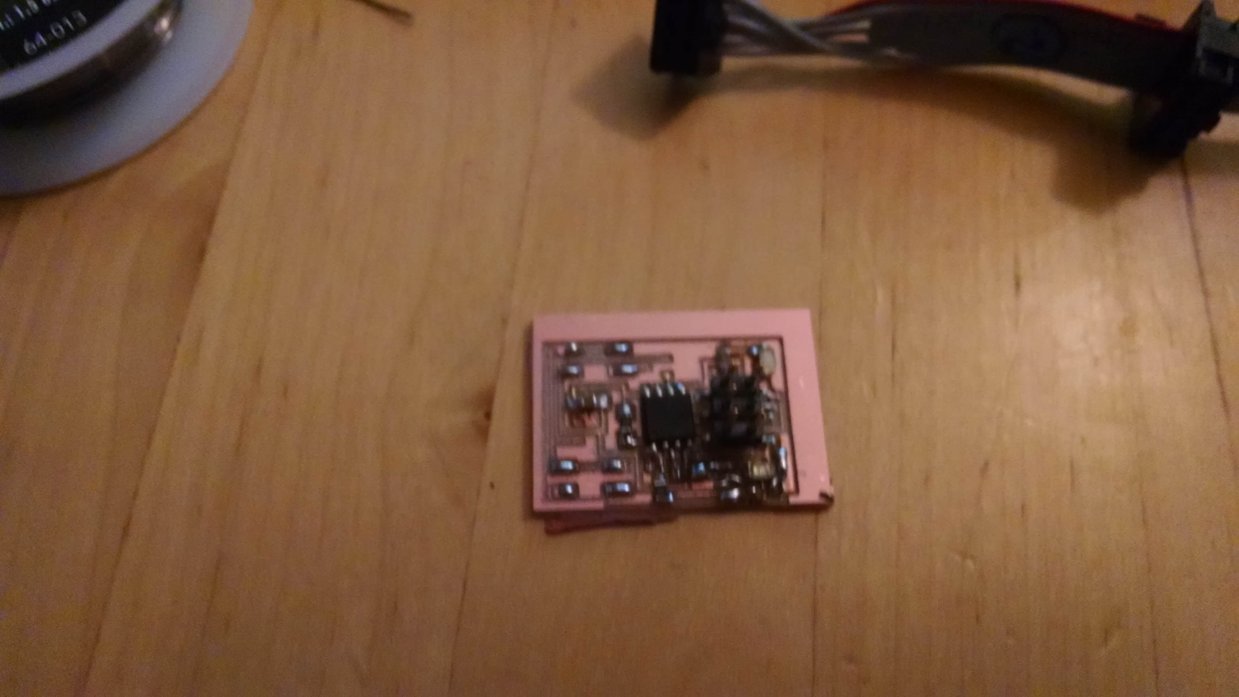
Here is my board. It has been edited using Pixlr. New traces were added to the unused pins. As opposed to redesigning
the board with Eagle, adapting an existing board was much faster.


My Arduino IDE code:
    void setup() {

    pinMode(0, OUTPUT);
    digitalWrite(0, HIGH);
    pinMode(2, OUTPUT);
    digitalWrite(2, HIGH);
    pinMode(4, OUTPUT);
    digitalWrite(4, HIGH);
    pinMode(3, OUTPUT);
    digitalWrite(3, HIGH);
    }

    // the loop function runs over and over again forever
    void loop() {
    digitalWrite(2, HIGH);   // turn the LED on (HIGH is the voltage level)
    digitalWrite(4, HIGH);
    delay(1000);              // wait for a second
    digitalWrite(2, LOW);
    digitalWrite(4,LOW );// turn the LED off by making the voltage LOW
    delay(1000);

    }
The piezo can be tested using the example: PlayMelody
Here is the board:
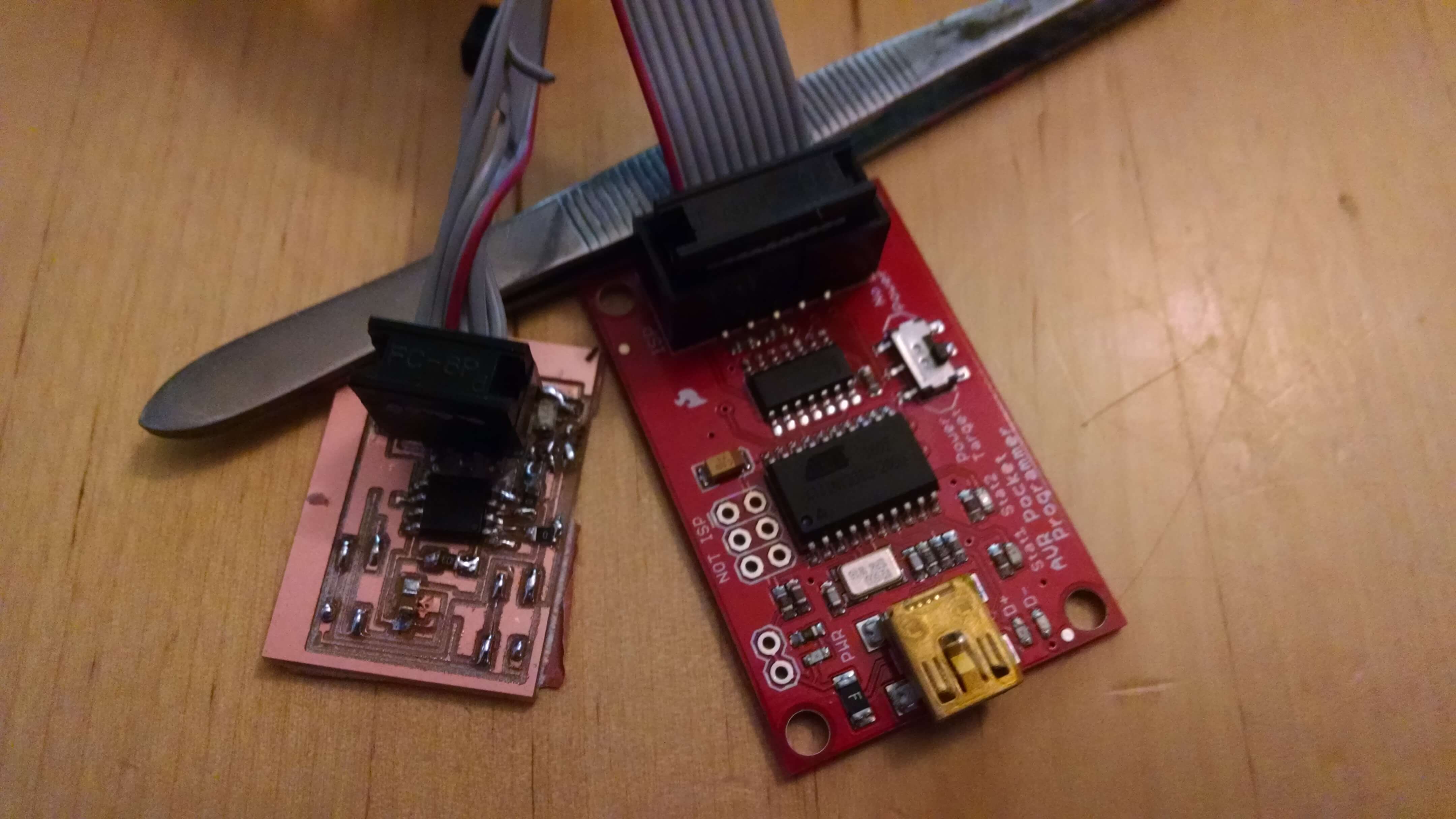
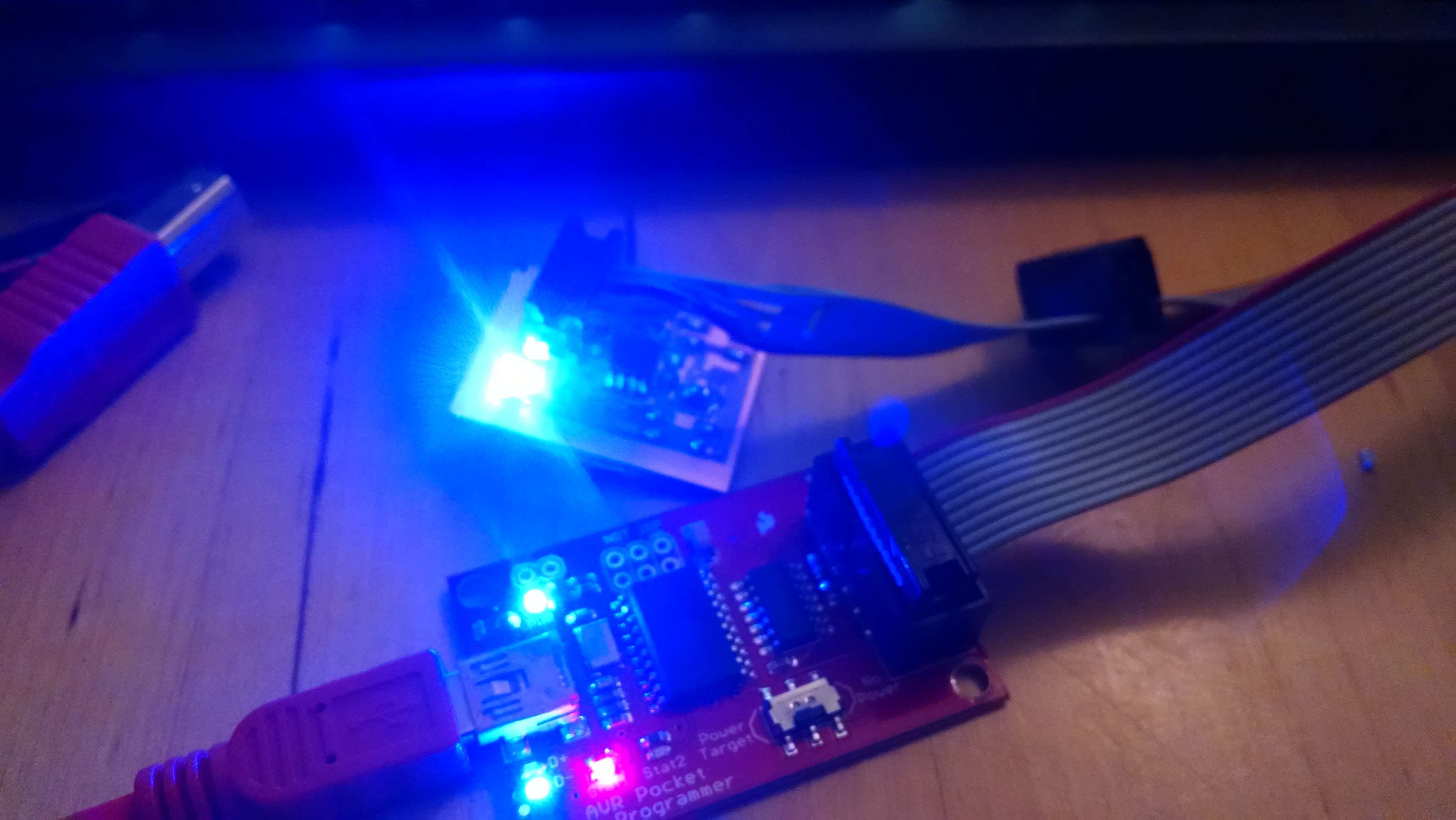
1.)Soldered Board 2.)Board with Programmer 3.)Board with 3 leds blinking

