Networking and Communication
For this week the assignment says that we need to build a wire or wireless network of at least two components. I choose to use a serial asynchronous communication. Asynchronous communication is when a client can ask several times to the server without the need to receive a reply. In my case I am going to redesign the files for asynchronous communication.
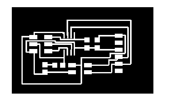
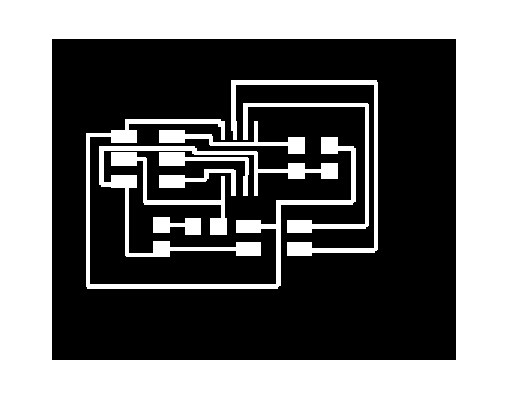
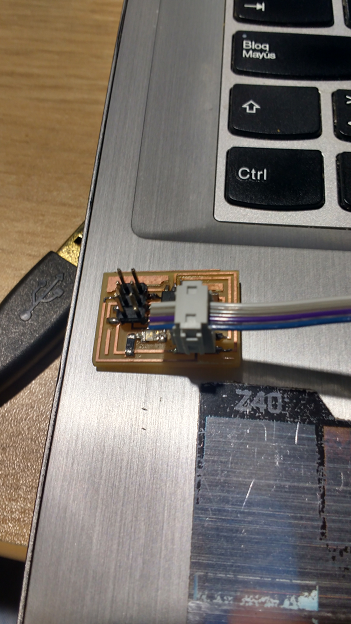
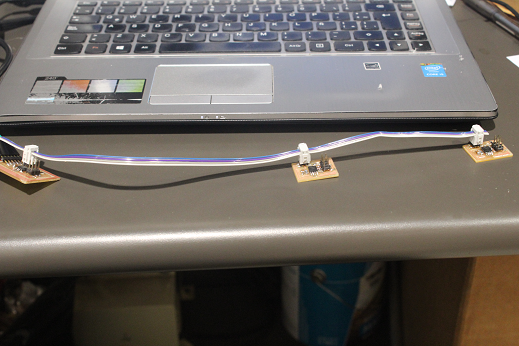
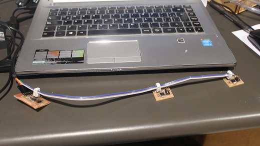
First I downloaded the png files, milled the board and soldered the components. I build 1 bridge and 2 nodes. The result is shown:
Original


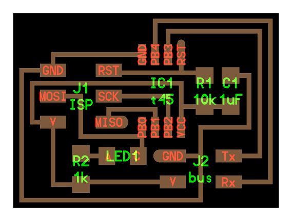
The difference between both devices is only at the add of the FTDI pins. The program to be burn as taught during the first week is the same for all the devices. However, some changes can be done. Inside the hello.bus.45.c file is a code line saying “ #define node_id '0' ”. If the number is change by other char variable we can personalize each device. In my case I won’t change it.
For starting serial communication I opened the serial port from Arduino IDE. This is perfect because it allows communication in a simple and fast way. Just for dummies! (I love those procedures).
The next video shows the result. Whenever a character is send the lights in all elements flash once. However, if a 0 is send, the LEDs flash twice.
The only problem I had was when I tried to change the "defined node id" to recognize different commands I got confused. It happened for not identified the devices physically. What I mean is that is impotant to keep track of the digital changes done in devices. Instead of having not 2, but lets say 20, it could be a nightware.
Download all the files from here.