Mechanical Design
The machine that we built decorates cakes with a radio of 35 cm. The group decided to make a Core XY design with an external extruder. The decorative "ink" is transmited through a tube that is hold with a special structure. For more information about Core XY configuration look his link: Core YX. We also added a Z axis in case the height of the cake varies.
To build the machine, we decided to use 3mm MDF and laser cut for two main reasons:
- The cost of materials decrease significantly when compare to thicker objects.
- The laser cut is faster than the milling machine, so any change in the design can be rapidly update.
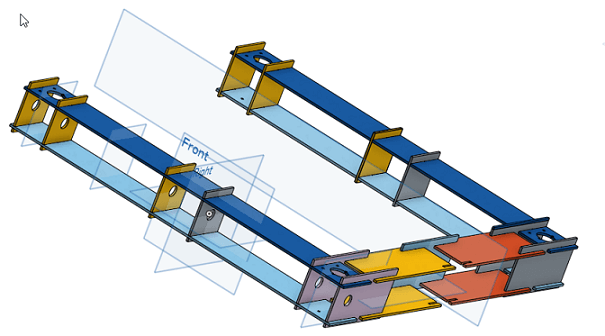
This considerations are important because they are going to influence on the design. How? For starters, because of the Core XY configuration, the stepper motors have to be over the XY frame, generating a torque that bends the structure. The first idea that came to our mind was to design a double layer board with holes to introduce MDF "locks". But we encountered one main problem: our laser cutter is not big enough for manufacture the dimension we need. That is why it was necessary to create separate pieces that join together by some small boards for the frame. The next image shows it.
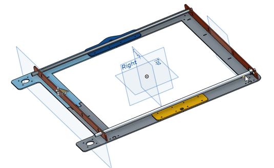
However, after a few hours of built, the machine started to bend because of the motors. They were to heavy for the structure. That is why the design was changed adding two more long sticks at the sides, making a square. It was pretty useful and the bending stopped.

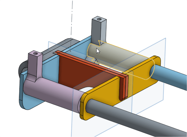
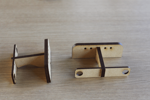
The issue with the Y axis during its drawing was how to introduce the corners for collocating the pulleys. The initial model has inside the piece a small stick:
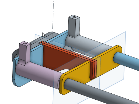
This model had several flaws. To begin, the corners were to weak to mantain the pulleys. Then, the bars could move inside its holes and be in a non-parallel position. In order to fix these problems the whole idea was rethought. The new arrangement consider a better way of mantaining parallelism between the bars and consider spaces for screws for the pulleys.
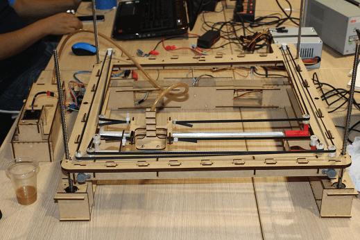
For the Z axis it was considered to use 2 stepper motors and 4 bars at each corner to give some stability to the machine. The picture shows one of the sides:
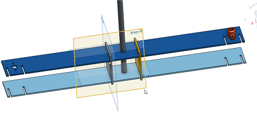
It was a terrible idea. The weight of the motors destabilized the system and the frame was leaned to one side. Summed to this trouble, the inclination generated friction over the bars, so it was more dificult to move along the Z axis. How do we solve this headache? There was 1 gestalt free and 2 stepper motor with shaft unused. The base was redesign in order to have the 4 motors over each corner.
Two designs were make for the tube holder. The last one is the one we used because of its style. Both of them work properly.
But until know we have only shown the drawings over the CAD. The following series of photos shown the whole process of building.

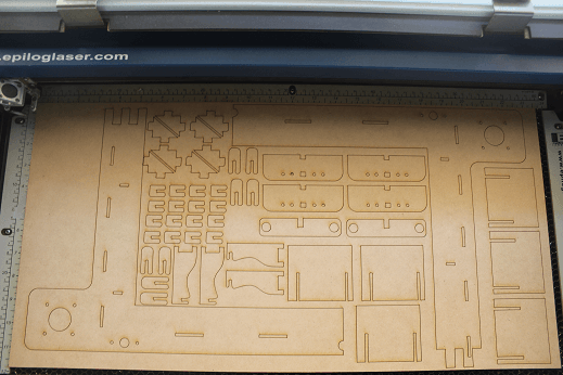
At first cutting the MDF boards. We use 6 for the whole structure.
Starting to assemble the pieces.

The long stick helps to give rigidity to the frame.

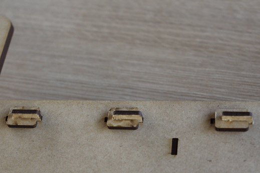
The MDF locks.
The frame is completely build.
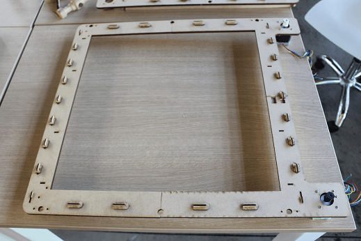
The next image displays the squared structure that prevent any bending.

The motor with the belt guide.

The holder of the stepper motor shaft is screwed to the frame.

The belt guide are put over the frame. These are made of 2 parts.

For the Y Axis first we cut the MDF pieces.
Then, we put together the rest of all the pieces.
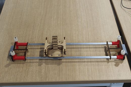
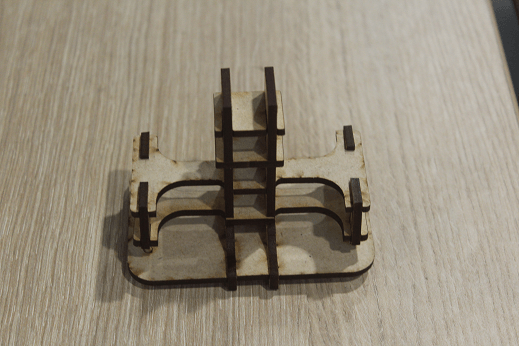
The first version of the frame:

For the base, the next pictures display how it looked one of the parts before the changes.

At the end of the assemble some spare parts were change, so the last version is like the following images exhibit:

The Onshape document is at this link.
The raw files are at this link.