Electronic Production
For the assignment of this week I had to create a FABISP. Initially I thought it was going to be easy because I have previously done some boards before, but I discovered, again, that I could't be further from the truth ... The lesson I learned this week was about humbleness. Not because someone knows how to do a procedure means that he understand and knows all the aspects related to it.
Initially I used the design of Andy. I downloaded the schematic and board files for eagle.


Then the files were exported at ".png" format, separating the traces drawing from the window image. To do this I simply change the display of the layers inside the softwware.

Once the copper board was glued to the sacrifice table at the Roland MDX-20, the fabmodule program was opened inside the computer connected to the mini milling machine and the parameters selectected were
Input: image (png)Output: Roland mill (rml)
The traces drawing was loaded into the software and the following parameters were selected:

I used the 1/64 milling bit fot this job. The followings buttons were pressed: make.path and make.rml. The milling bit was positioned at the lower left corner introducing the offsets at the boxes called "xmin (mm)" and "ymin (mm)" and, the "move to xmin, ymin" button pressed. Then I lowered the cutter using the buttons of the equipment until it touched and slightly pierced the copper board. This is vital because if you do not do it well, it can break the bit. After this, press the "sent it" button. The following window appears:
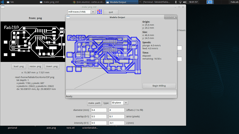
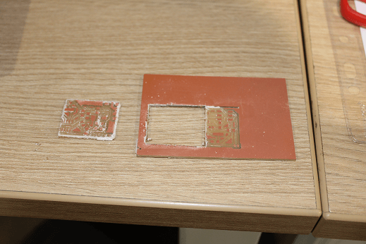
"Begin Milling" is pressed and the machine starts milling. So far so good. No problem. The pictures shows the result:

But then, in order to cut the plate, it is required to turn off the machine, something I did't do. The milling bit was changed, but the system was not shut down. Because of this the bit moved to the starting point and dropped down more than it should, breaking it. This, dear sirs, was for not listening indications ... So now I owe a bit to the lab ... but I learned my lesson ... if it affects my wallet I learn fast ...
Milling bit was changed for the 1/32 and continued with the process. The window image is loaded and the parameters of the next picture are placed:
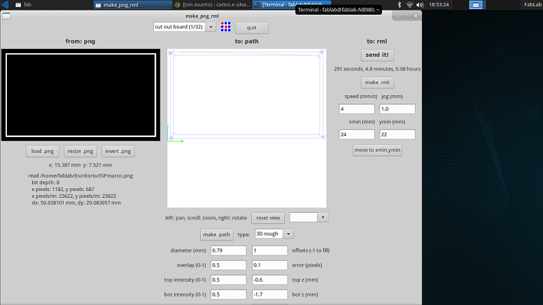
The last steps were followed, however, you should consider placing the bit at the corner, touching the plate, no drilling it. Otherwise, you end milling not only the frame, but also traces inside the copper board... And I did not realize it... and it was said earlier ... I misspend a board... another blow to my pocket ...
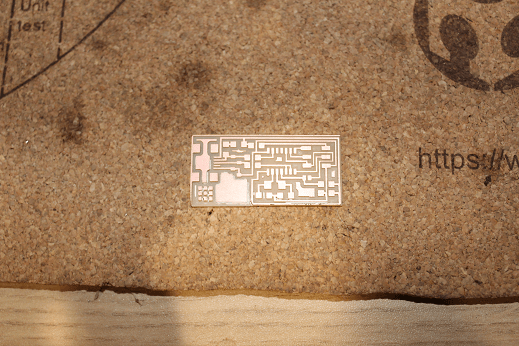
I repeat the whole procedure changing the layout by the file "hello.ISP.44.cad". The following image shows the result:
Now is the turn of soldering. Here I'll be honest: I hate soldering. It is not difficult, but I take a obscene amount of time because I always check the continuity of everything I do. I started soldering the ATTINY44 followed by mini usb port because they are the most difficult elements. Next were the resistive elements, capacitive elements and the 20 MHz crystal. The last thing left were the diodes since I didn't know whhat A and C referred in the schematic. After searching I found two concepts that I knew well: Anode and Cathode. Another blow to my pride (but not to my savings account this time). The pieces were welded and board remain as pictured:

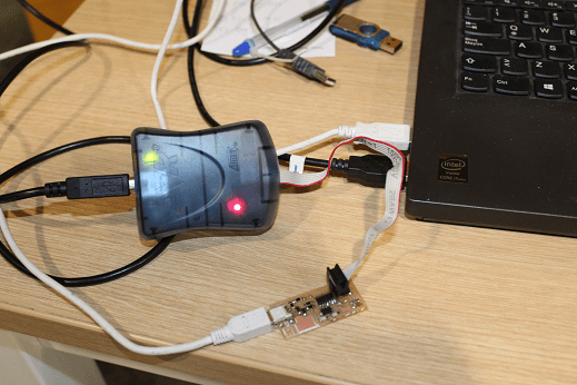
Finally, to set the ATTINY44, the board was connected to AVRISPMK II. In the image there is a red light. It should be green. What happened is that the pictured was taken after desoldering the jumpers and programming.
The Makefile was downloaded and change as indicated on the website of David. Instead of:
AVRDUDE = avrdude usbtiny -c -p $ (DEVICE)
It was used
AVRDUDE = -P usb avrispmkii avrdude -c -p $ (DEVICE)
Then the command window was opened in the folder containing the file and the next commands were introduced: make clean make hex (Sudo) make fuse (check programmer in Makefile, may need to repeat) (Sudo) make program
Finally, the jumpers (Res 0 ohms) of the plate were desoldered.
I want ot make a comment: unlike my colleagues, controller programming was done pretty quick, possibly because the time spendt at soldering and verifying every part of the work. I take more than over an hour and a half, but it was worth it because I was sure that there were no circuits problems.