Designing the Box for Dew Point Monitoring System.
My objetives
Build a little box that:
- Is as small as posible.
- Doesnt needs of glue or nails.
- Is made of a cheap material as MDF.
- Contains the input (humidity and temperature) and output devices (LCD), and WiFi board made in one of the assignments.
- Mantein the cables in a estructured layout.
- Protects the Fabduino of the manipulation of the cables during the assembly process.
Components to consider
- 600 X 300 MDF board of 3 mm.
- The Fabduino
- A DHT11 temperature and humidity sense
- A board for WiFi communication with the ESP8266 12E component
- A DHT11 humidity and temperature device
- A LCD display 16 X 2
- Premium Female/Female 'Extension' Jumper Wires - 40 x 6" (150mm)
- A 10k Potentiometer.
- A 220 ohms resistor.
- A FTDI cable
Process
I had the option to build a simple box, but some of my objetives wouldn't be accomplished, instead, I involve in a detailed, and laborius, but funny process of building, I think, a nice and functional box, as you will see. It took me some hours, and 3 MDF boards.
Lessons learned.
- Making a customized design is a laborius but exciting actvity.
- I lost a MDF board because I received an 4mm board intead of 3mm and I didnt verify.
- I design some intermedial layers inside the box for arraning better the cables, that was a good idea. It also allowed the objetive of holding some the cables and not moving the pins of the boards. Becasuse I had a previous experience with Fabduino, that the external pins were broken with a movement.
- Creativity is needed to achieve all the above objetives mentioned.
I f you want to Download it, the dxf file is here.
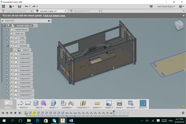
I used the Fusion 360 software to design.
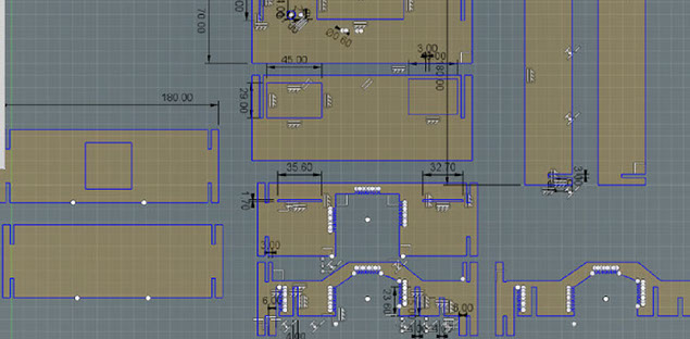
To download, the dxf file here. Some views of the design are here.
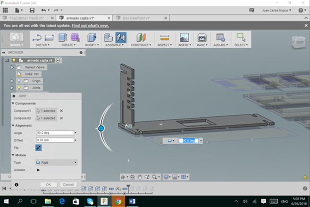
Not nails or glue are needed. Pressfit technique is used.
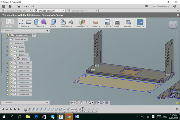
The intermediate levels are designed to better arranging and fixing of internal cables.
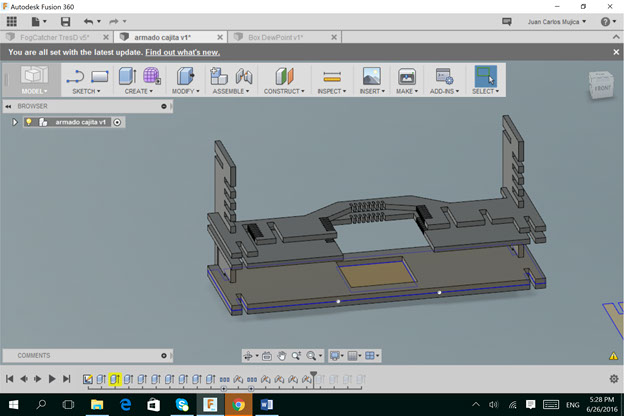
Rear part is hollow to allow the sensors and actuators not be closed.
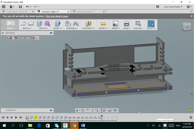
As this screenshot displays, the assembly can be done once half part of 3D structure is assembled. It allows maneuverability to connect components and not damage any part.
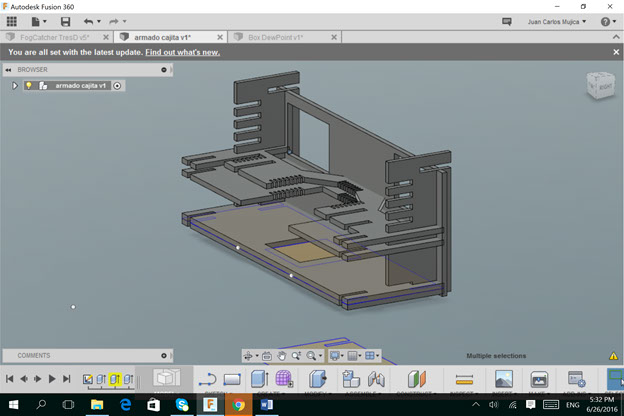
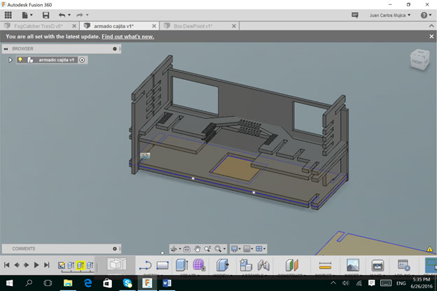
The box almost finished, only is needed to put the top cover, that is also divided into two parts.
.