Week 8
Embedded Programming.
This week we will program the microcontroller with different programming languages and environments.
1- Install avr-gcc, avrdude. Write sudo apt-get install avr-gcc avr-dude in a terminal.
2- Read the chapters related to I/O ports from Datasheet.
To get started with programming in C, I wrote a simple code to turn the LED on/off using the switch. The basic blocks of the code is :
1- Configure switch pin as input
The DDRx configure the direction of the pins. 1 means output, 0 means input. 1<<PA7 outputs 0b10000000 then ~ inverts all the bits to be 0b01111111. &= makes logic AND on 0b01111111 and the current value stored in DDRA. We do this because we don't want to change any of the other bits. If the bit was previously 1 so 1 & 1 is 1, else if it was 0 so 1 & 0 is 0. This way we will just change PA7 to be 0 and leave the other pins.
2- Configure LED pin as output
The same but this time we used Logic OR to just change the value of the pin we are interested in.
3- Loop forever and read the switch and if it's high, turn on the LED and vice versa.
The PINA means read port A. We perfome a logical AND between values we read from port A and 0b10000000 to read only pin 7.
I like to use make (a unix tool for building program executables) instead of writing long commands everytime i want to compile the code.
I edited the Makefile from the class archive.
Download the source code:
Switch.cCompile the code by writing make -f switch.c.make
Configure the fuses by writing make -f switch.c.make program-usbtiny-fuses
Upload the HEX file by writing make -f switch.c.make program-usbtiny
The LED is off.
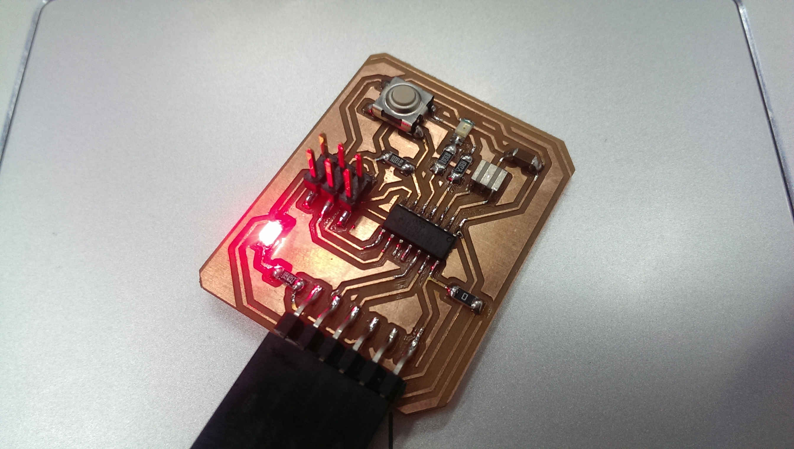
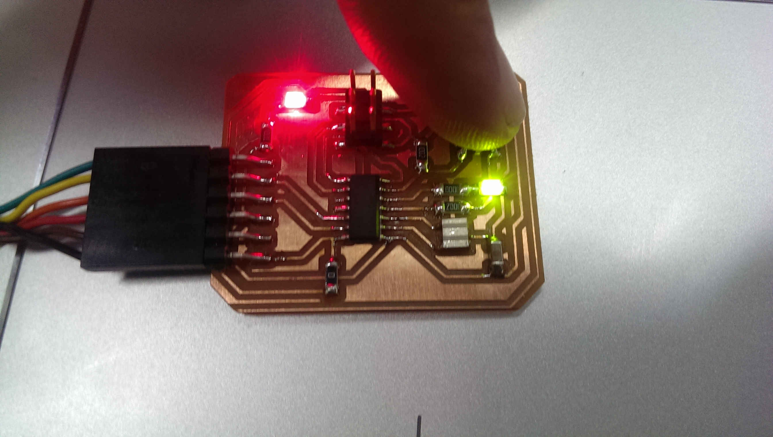
Pushing the button, LED is on.
The next step is to make the board talks the computer. I modified this code from class archive to add the communication part and added a few lines to control the LED via the button and report the status of the LED to the computer.
I used the same process to compile the source code and to upload the HEX file to the board.
Download the source code:
Switch-ftdi.cCompile the code by writing make -f switch-ftdi.c.make
Configure the fuses by writing make -f switch-ftdi.c.make program-usbtiny-fuses
Upload the HEX file by writing make -f switch-ftdi.c.make program-usbtiny
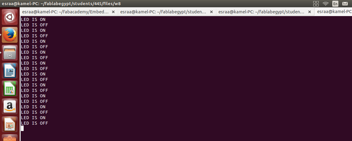
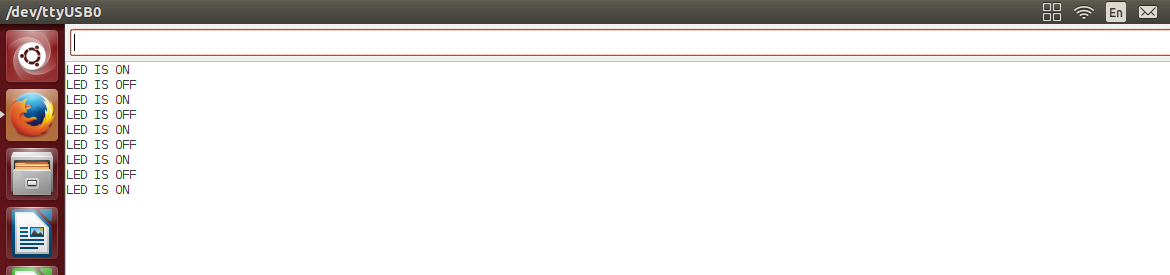
Using screen to connect to the board. The boards sends the status of the LED to the computer.
Here is a GIF of the board in action.
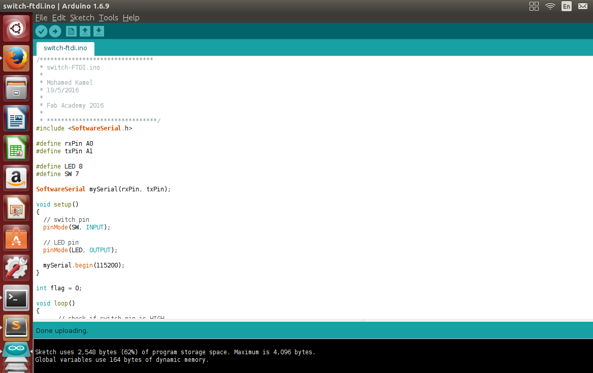
To program the board using arduino i had to add the Attiny44 microcontroller to the boards in the IDE. I followed the tutorial in this site.
Arduino language is pretty easy and the refernce is very handy. I wrote the same code as the last one and added a simple feature to control the LED from the computer by sending 1 or 0 via serial terminal.
Download the source code:
Switch-ftdi-serialcontrol.inoBefore compiling I choose the board from tools>board>attiny44 20MHZ external clock then choose the programmer from tools>programmer>USBtiny, and finaly I compiled by clicking on compile from sketch>compile sketch.
To upload the code. Click on Upload using programmer from sketch menu
It's working !
I also programmed the board using codebender, but it is not so different from the Arduino IDE.
You can view the source code on codebender from this Link.
That's all folks !