2016
Rudrapalsinh Solanki
Week-7
Computer-controlled machining
Assignment
1.Make something big( Furniture/ element)
For this week I started searching for the mono-cock structure that can withstand by itself. Then I thought If such structure has to be built than why now I can design a pavilion which is like a interlocking structure that can be made easily and can stand on its own weight and structure.
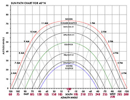
I had a work to design something on the energy standards and that too which is huge 4mts*6mts and 2.4mts tall.
So I decided to make a pavilion in which people can move in and out and the element itself becomes a solid reason for people to stop and look at it. As this element had to be kept in the exhibition so I took the decision to build it first in a 3D software and then take it into the construction of it.
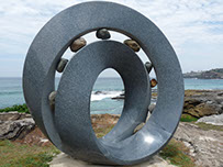
These are the examples that I refereed first to understand the form of the built and so I can design the pavilion accordingly.
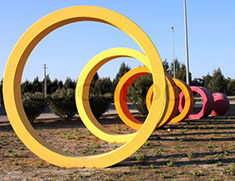
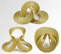
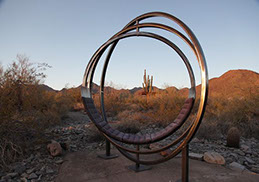

After looking at these examples i started developing the form in Rhino.
Once the form is finalize then I can start the ideation for the construction of the pavilion.
These are the exploration for the form that I worked out in rhino modeling.
.jpg)
.jpg)
.jpg)
.jpg)
Looking at the options from the 3D generated files in Rhino
.jpg)
.jpg)
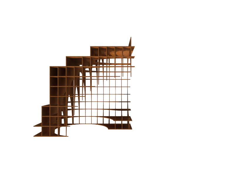
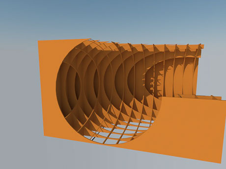
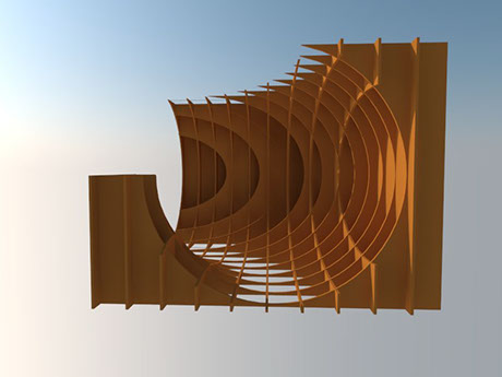
This the final selected 3D volume that I will take it further to develop and add the construction technique to it.
.jpg)
.jpg)
This the final selected VOLUME that I edited a little the element coming in front was deleted till the mid of the corner. Then the structure of the pavilion is finalized and the interlocking of the sheets were made.
.jpg)
.jpg)
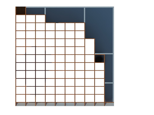
Then the structure is detailed out in the single line drawing. Once the line drawing of all the members/components are done it can be easily seen that there are no issues at the connections and all the connections are neat and now ready to make the shopbot files.
.jpg)
.jpg)
Before moving to the fabrication drawing of the pavilion I RENDERED THE VIEWS of the structure to get the understanding of the whole pavilion and to know the kind of space derived by it.
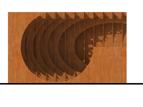
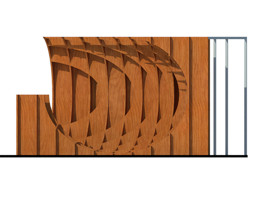
VIEWS OF THE STRUCTURE AFTER REMOVING THE EXTRA MATERIAL FROM THE LEFT HAND SIDE STRUCTURE.
FABRICATION PROCESS AND THE CONSTRUCTION OF THE PAVILION
The first step is to number the elements/ all the components so later there is no mis-understanding while making and milling. I numbered the 2 sides of the Structure.
The one in the x plane is numbered as A series that has numbers from A-1 to A-12.
The one in the y plane is numbered as B series that has numbers from B-1 to B-10.
And the drawing also consists of the dimension of the elements and the distance between the individual elements.
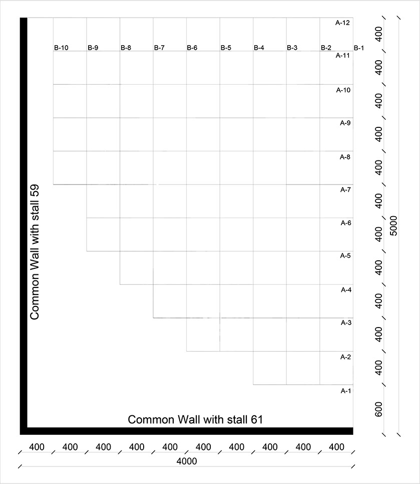
The material that will be used for the construction will be MFD sheet of 18 mm thickness. The interlocking of the MDF sheets is worked out accordingly. The height of the pavilion is 2400mm that is 8ft. The MDF sheet size is 4ft *8ft i.e 1200mm*2400mm.
So I DECIDED TO DIVIDE THE PAVILION INTO 2 HALVES i.e THE UPPER HALF AND THE LOWER HALF. So the wastage of MDF sheet is very less.
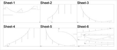
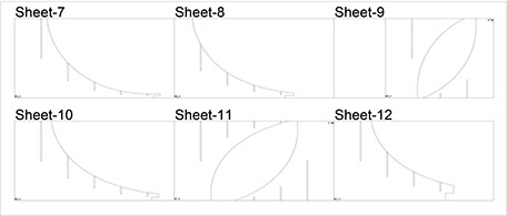
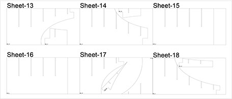
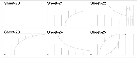
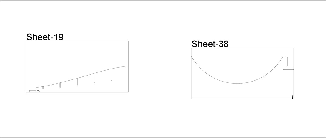
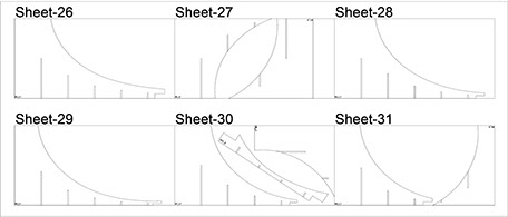
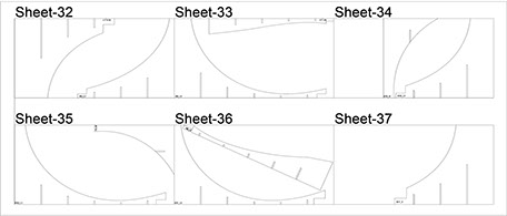
These are the basic working files from the rhino software.
.jpg)
.jpg)
.jpg)
.jpg)
.jpg)
All the sheets were composed into the dimension of the 8ft*4ft sheet size, so it becomes easy to mill the sheets.
There were total 38 sheets were to be used for the construction of the pavilion and the extra wastage of the pavilion was used to make the boxes.
Once the files are ready now the files are taken to the shop bot for further fabrication of the pavilion.
DIGITAL FABRICATION OF THE PANELS
After all the files are made then the work of mill will start.
For milling we had a Shop-bot so I just had to now set the sheet into the bed and give the commands to the shop bot to cut the sheets according to the files that I have made.
The first stage was to cut the files of the lower half of the structure and also to see if the sheet that are milled has a numbering according to the drawing.
For making the files for shop-bot we use PartWorks. You can download the trial version of the software from this LINK

This is how the logo of the PartWorks look.
Once the partWorks is installed now I opened the software and added the first file to the software.
PartWorks is a CAD/CAM program that will easily give designing for CNC cutting and machining. This 2.5D design system has a highly acclaimed interface that makes it easy to get your ideas and designs ready for your ShopBot to cut.
In addition to doing great cutting of 2D parts, PartWorks has excellent capabilities for 3D V-Carving (machining that gives letters and shapes a chiseled look; also referred to as Intaglio or 3D Engrave).
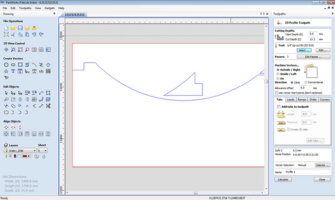
The screen of the partWorks look like this:
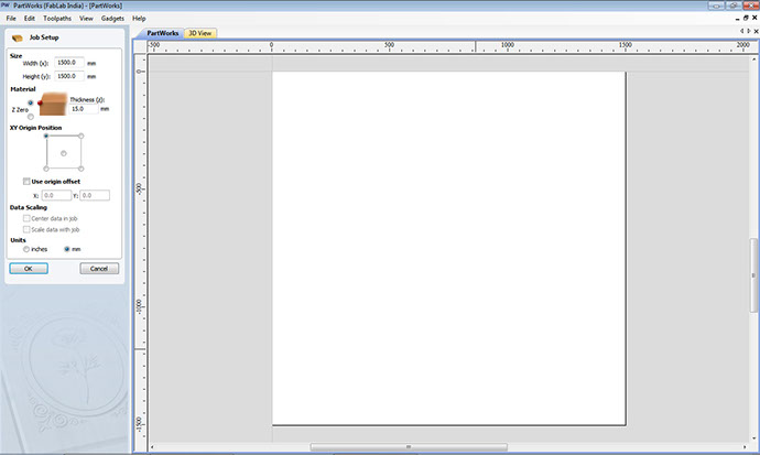
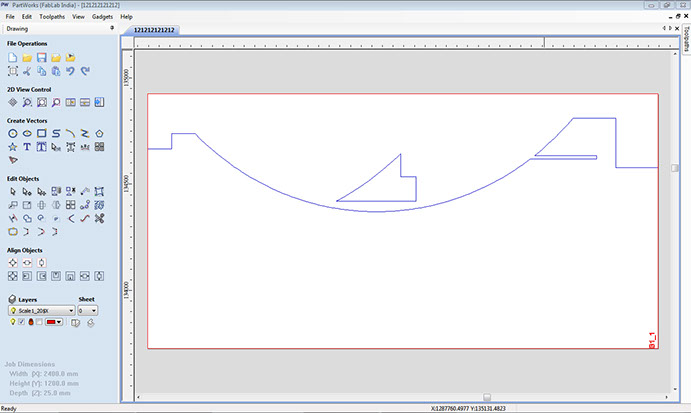
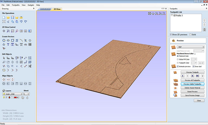
Once the window is opened then the file is loaded into the partWorks:
After loading of file the material thickness is given and and z axis is set for the milling.
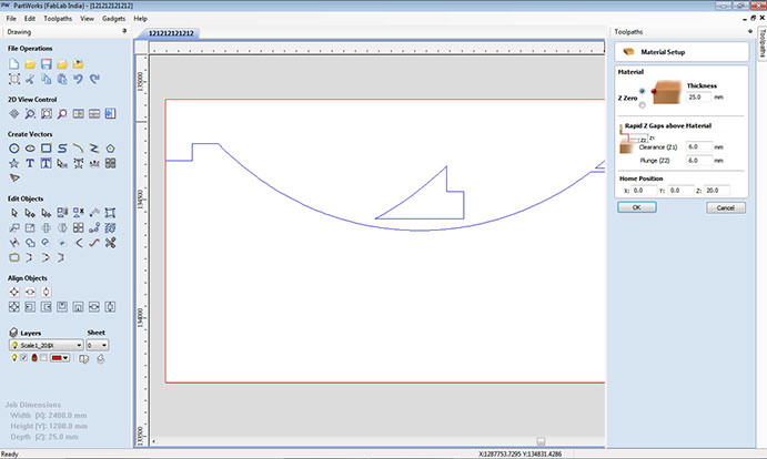
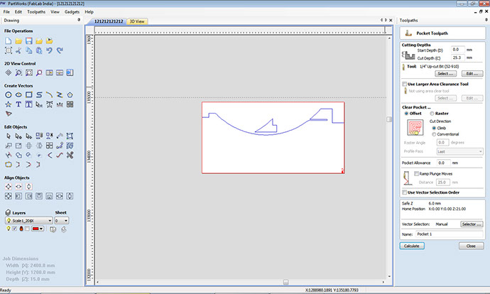
I wanted the profile to be cutted so selected the option and given the specifications for cutting.
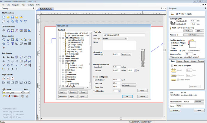
The drill bit is selected and the number of passes is selected.
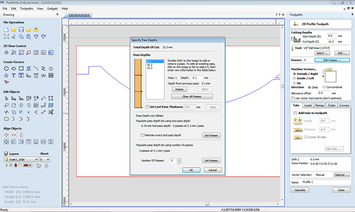
Once the passes are selected, I rechecked it with the cutting depth at one go.
Its time to see how the tool moves and what is the flow of the cutting.
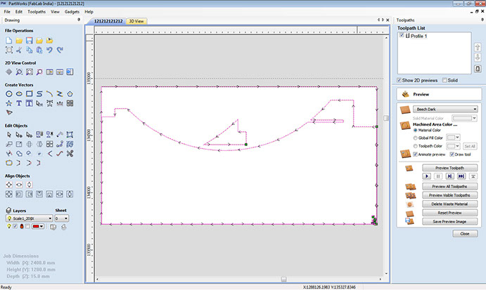
After the flow I checked it in the real time render effect that the sheet is looking perfect.
Last but not the least I set the cut depth and calculated the path to be taken by shopbot.
After the path fixed and a small video can be seen on the software and the resultant can be seen.
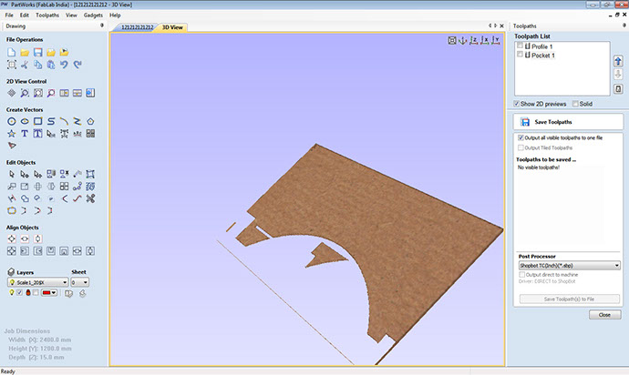
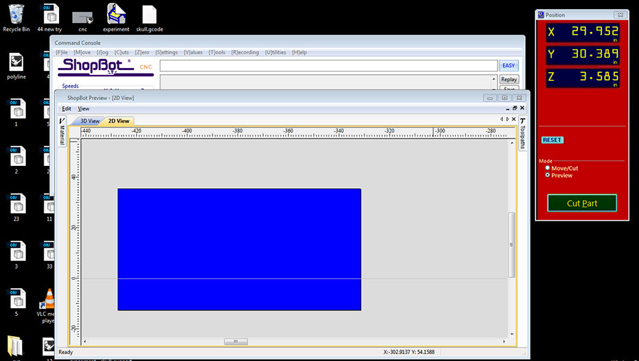
After the file is ready now its time to mill the sheet. So I opened the Shopbot software to cut the file.
Most important task was to set x/y zero first placing the left side top most corner zero for both the axis.
Now its time to set z of the shopbot.
Once the zero is set for all 3 axis. Now I am ready to open the file and mill the file.
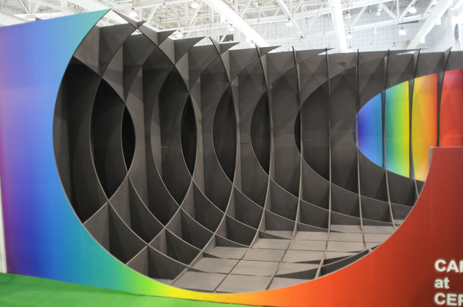
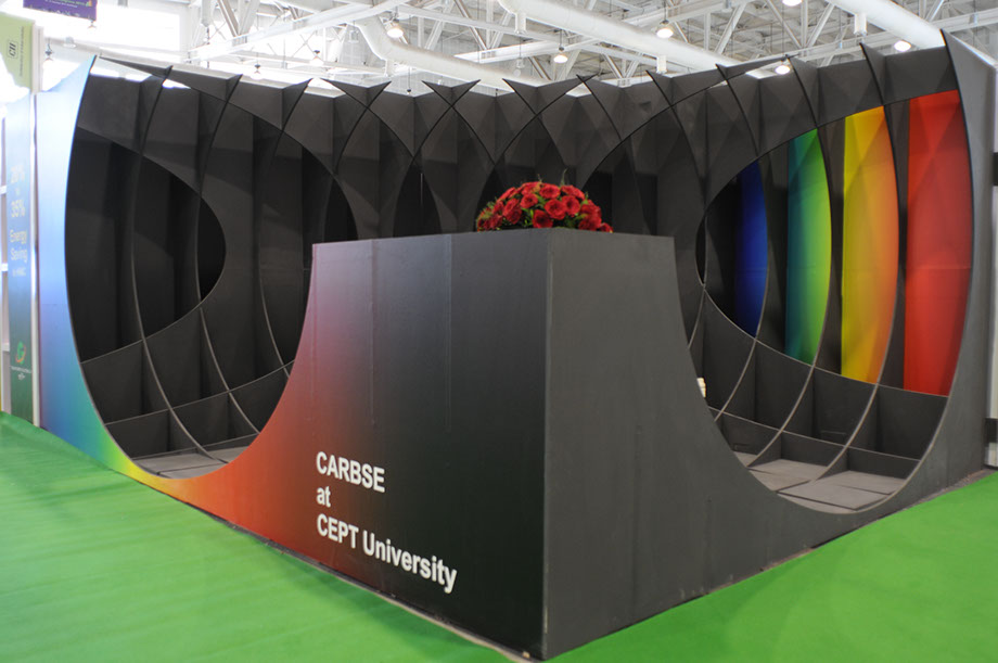
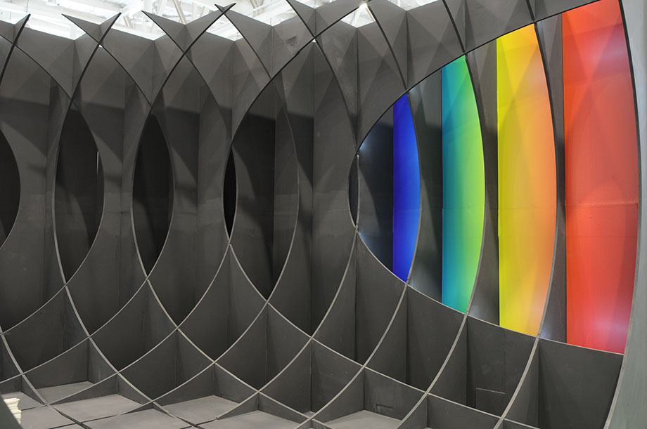
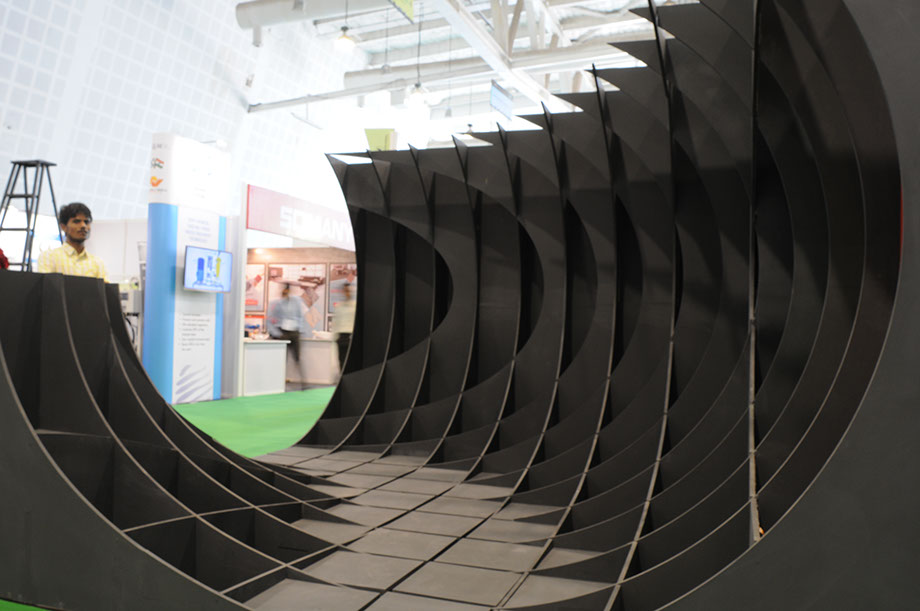
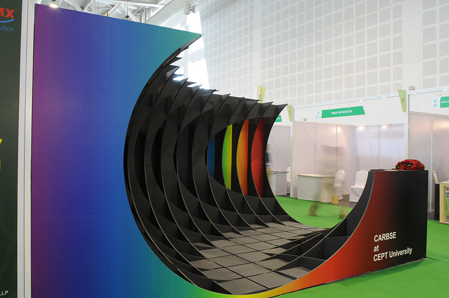
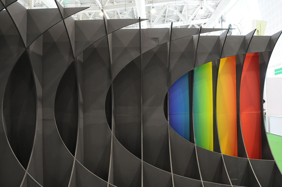
FINAL OUTPUT OF THE WORK: It was looking really good at the end
Week 07 Files
Once the files are set for the cutting now i am ready for the milling process.
Each sheet numbered and the milled piece are placed in sequence.
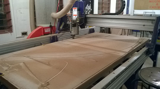
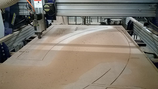
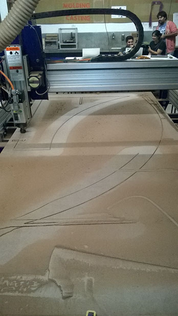
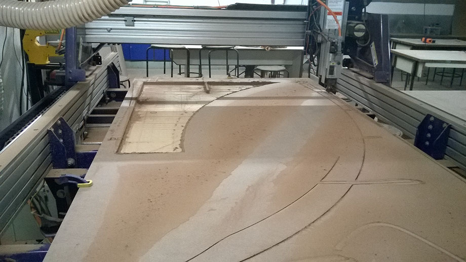
All the components are cut one by one, It took 2 days 8 hrs each day to do all the milling. I was not able to document the detailed cutting of the sheets, was in hurry to finish the cutting.
After all the cutting is done now its time to paint the sheets with black matte color. I had 2 helping hands with me to do the paint job of all the 40 sheets as It was a huge job to do the paint the sheets on both the sides.
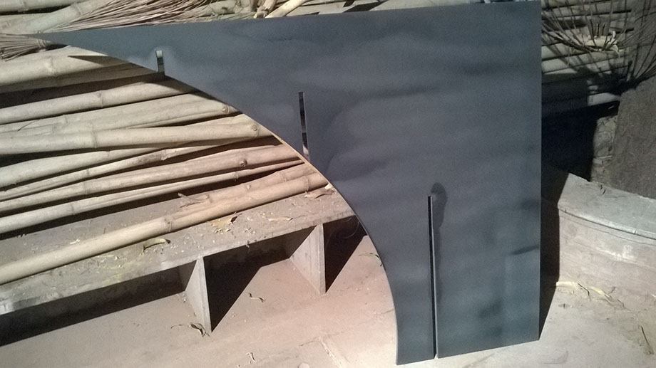
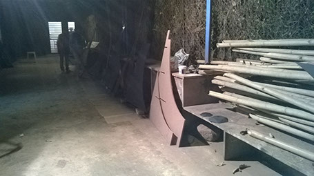
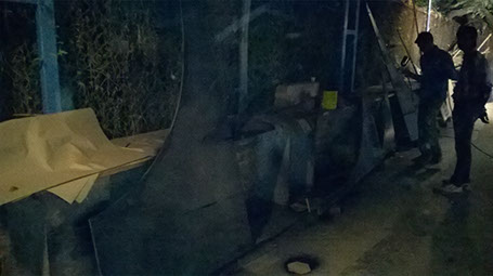
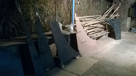
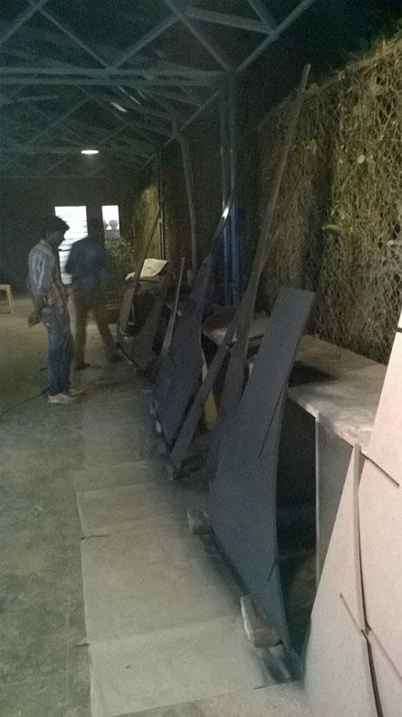
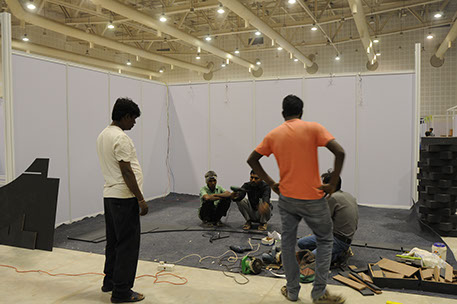
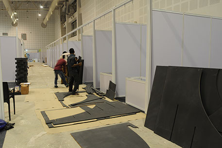
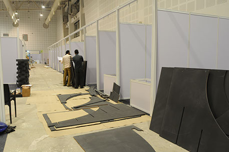
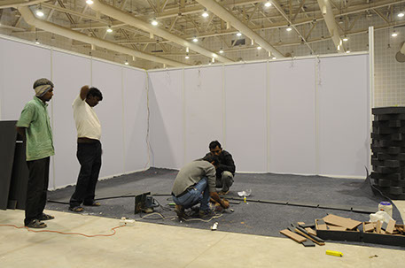
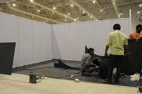
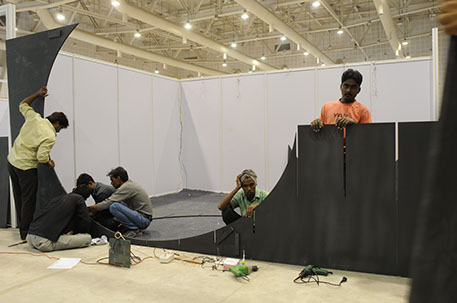
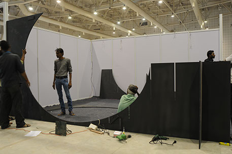
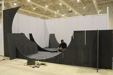
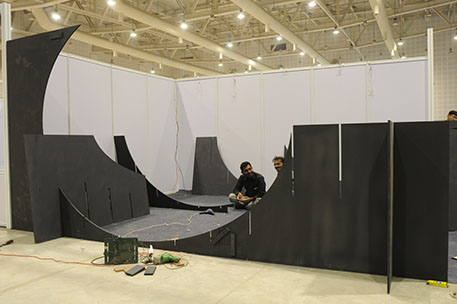
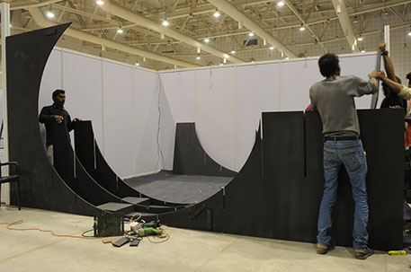
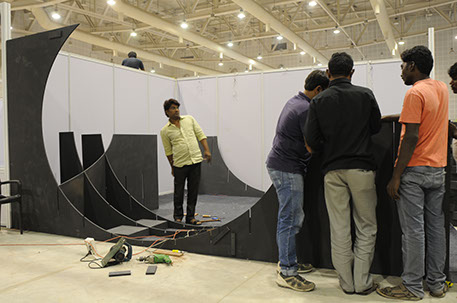
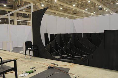
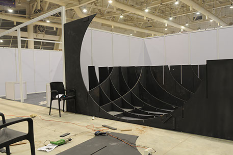
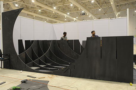
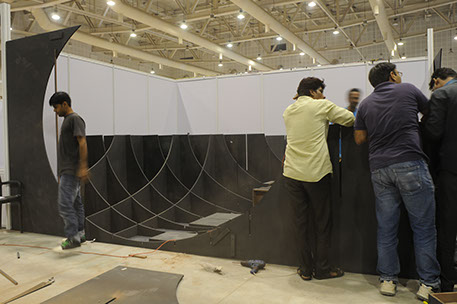
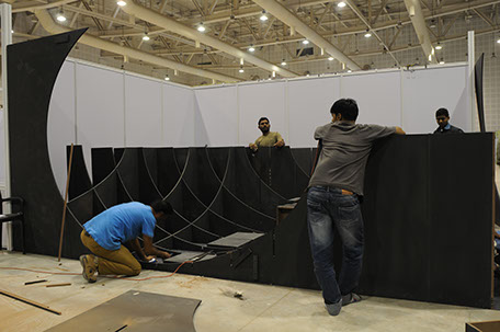
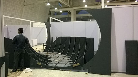
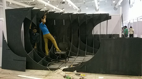
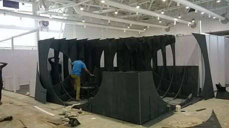
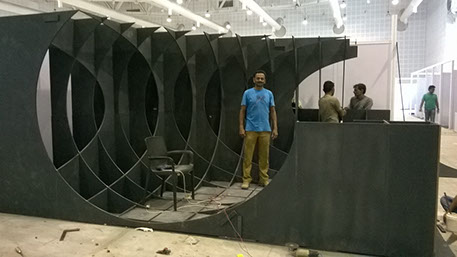
After the cutting and the paint job of the sheets were done. Now I am ready to see it assemble and see how does it look.
I took all the painted components to the Gandhinagar and now it is ready to assemble.
Now this time I AM READY WITH MY CAMERA THIS TIME TO DOCUMENT EACH AND EVERY STEP FOR THE CONSTRUCTION OF THE PAVILION.