
2016
Rudrapalsinh Solanki
Week-2
Computer-aided design
Assignment
1. Model or raster the final project
Rastering the Final project :
I have studied design in my education, so my drawing making skills are already there. As the design is not finalize yet, the final project (6 Axis robotic Arm) works on a base defined and attached to the arm.
The drawing are done in the form of basic sketches at the first level so the arm can rest and can perform its activity in all the axis. The sketches done accordingly to the construction of the arm and also according to the function.
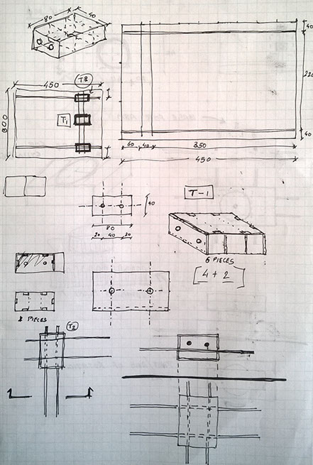
For making the cad drawings I need to finalize a form with the necessary dimensions and basic elements needed for the drawing.
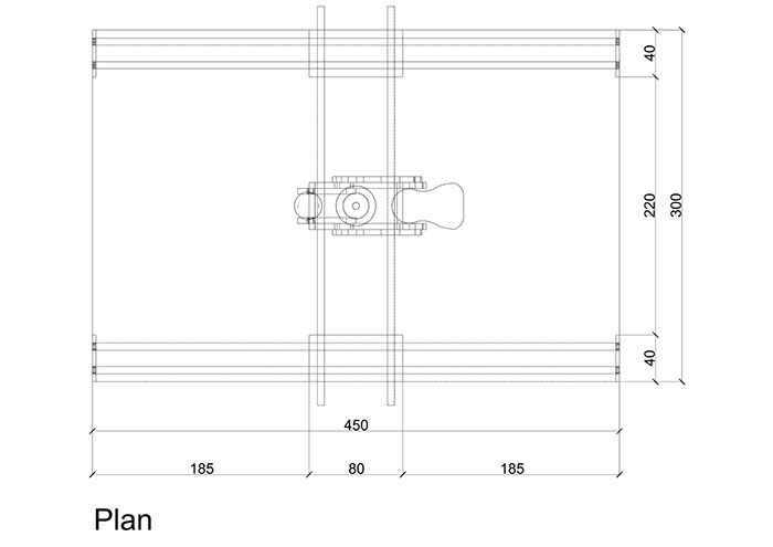
Sketches of the final project for deriving the dimensions and creating the final form.
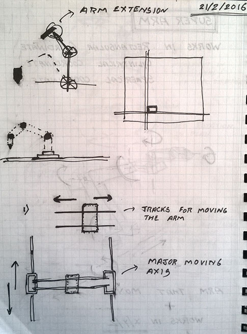
Once I made all the sketches required for the drawing 2D vector file for the Arm, the sketches are further used for the development of the structure of the Arm. It explains all the movement in the initial stage and also describes all the necessary moving/ rotating parts and also the sliding base plate.
The software used for creating 2D and 3D of the final project is Rhinoceros. To download software refer to the LINK
Rhinoceros it is typically abbreviated as Rhino3D is a computer-aided design (CAD) application software developed by Robert McNeel & Associates. Rhinoceros geometry is based on the NURBS mathematical model, which focuses on producing mathematically precise representation of curves and free-form surfaces in computer graphics.
I have worked on Rhino for developing the raster file of the final project. This is a prototype of the 6 axis arm as the final form is not yet evolved so the raster file that is made has basic dimension of the model and It includes the moving points /axis where the arm is suppose to me moving.
WORKING of RHINO :
How does rhino work?
Rhinoceros is used for various processes such as computer-aided design (CAD), computer-aided manufacturing (CAM), rapid prototyping, 3D printing and reverse engineering in industries that include architecture, industrial design etc. as well as for multimedia and graphic design.
This application software had been developed by Robert McNeel & Associates in the year 1980.
This software can primarily be considered as a free form surface modeller that utilizes the NURBS mathematical model. There are a lots of plug-ins available that complement and expand Rhinoceros' capabilities in various fields like rendering and animation, architecture, marine, jewellery, engineering, prototyping, and others.
Also, this application supports two scripting languages one is the Rhinoscript (based on VBScript and Python . Moreover it supports a parametric modelling/visual programming tool called Grasshopper that has the ability to create complex algorithmic structures.
File format
The Rhinoceros file format (.3DM) is useful for the exchange of NURBS geometry. The Rhino developers started the open NURBS Initiative to provide computer graphics software developers the tools to accurately transfer 3-D geometry between applications. An open-source toolkit, openNURBS includes the 3DM file format specification, documentation, C++ source code libraries and .NET 2.0 assemblies to read and write the file format, on supported platforms (Windows, Windows x64, Mac, and Linux). The McNeel Wiki has more current information.
For more Information please refer to the LINK
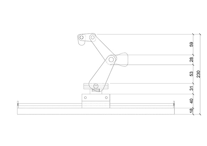
Elevation
3D of the same arm is developed in Rhino software. The 3D is developed in stages of phase by phase construction of the arm.
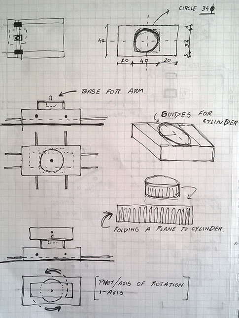
First the base is formed which works as a working bed for the arm.
The bed has 2 guides that supports the arm and allows the arm to move in x and y direction along the bed.
Once the guides are set than the base of the arm is fixed to the guides.
The base is placed in such a way that it can move to +x to -x and +y to - y.
The vertical members are connected to the base support in step 4. This member helps the arm to move in y axis and will rotate in y axis with the base as a pivot point.
In the next step the arm extends to join another vertical member that has a ball socket joint and it allows the arm to move in forward direction.
The vertical arm gets connected to the ball socket joint and it transforms into the main extended nozzle.
The nozzle of the arm can be a milling machine or it can be a gripper that holds and works.
Once the 3d is complete it is rendered in V-ray fro rhino which is an additional plug-in to rhino for rendering.
All the materials are applied to the model and It is rendered in vray to give the visual look of the final model.
.jpg)
STEP_01
STEP_02
.jpg)
STEP_03
.jpg)
STEP_04
.jpg)
STEP_05
.jpg)
STEP_06
.jpg)
STEP_07
.jpg)
STEP_08
.jpg)
STEP_09
.jpg)
STEP_10
Once the 3d is generated the of the project it is rendered in V-ray for Rhino applying the materials.
The stages of the construction is as follows:
.jpg)
Week 02 Files