2016
Rudrapalsinh Solanki
Week-16
Interface and application programming
Assignment
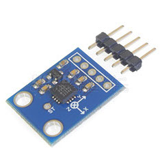
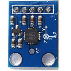
1. Making and application to see the visual in the computer with a GY-61 ADXL335 Triple Axis Accelerometer / Analog Sensor
2. Write an application that interfaces with an input &/or output device that you made. I used Button and RGB Led for this exercise.
For this Week I wanted to try something new with an Analog sensor(3 axis)
I wanted to make a INTERACTIVE application that works with an accelerometer .
The interface is developed in ARDUINO MPU 6050.
Processing is a flexible software sketchbook and a language for learning how to code within the context of the visual arts. Since 2001, Processing has promoted software literacy within the visual arts and visual literacy within technology. There are tens of thousands of students, artists, designers, researchers, and hobbyists who use Processing for learning and prototyping.
For more reference refer to the LINK
I downloaded Processing IDE(Integrated Development Environment) from the above link and then started working with Java language. Here are the screen shots of the process and the final result.
Once the LINK is opened and it is downloaded.
.jpg)
Once you install the processing , this is the window that opens up.
.jpg)
After the installation of the processing we need to download the libraries
.jpg)
Once the libraries are downloaded, the zip folder is extracted in the folder
.jpg)
.jpg)
Now open the processing window
The window of the processing looks like this:
.jpg)
This is the basic code that I used:
import processing.serial.*;
import processing.opengl.*;
import toxi.geom.*;
import toxi.processing.*;
ToxiclibsSupport gfx;
Serial port;
char[] teapotPacket = new char[14];
int serialCount = 0;
int aligned = 0;
int interval = 0;
float[] q = new float[4];
Quaternion quat = new Quaternion(1, 0, 0, 0);
float[] gravity = new float[3];
float[] euler = new float[3];
float[] ypr = new float[3];
void setup() {
size(300, 300, OPENGL);
gfx = new ToxiclibsSupport(this);
lights();
smooth();
println(Serial.list());
String portName = "/dev/ttyUSB1";
String portName = "COM4";
port = new Serial(this, portName, 115200);
port.write('r');
}
void draw() {
if (millis() - interval > 1000) {
port.write('r');
interval = millis();
}
background(0);
pushMatrix();
translate(width / 2, height / 2);
float[] axis = quat.toAxisAngle();
rotate(axis[0], -axis[1], axis[3], axis[2]);
fill(255, 0, 0, 200);
box(10, 10, 200);
fill(0, 0, 255, 200);
pushMatrix();
translate(0, 0, -120);
rotateX(PI/2);
drawCylinder(0, 20, 20, 8);
popMatrix();
fill(0, 255, 0, 200);
beginShape(TRIANGLES);
vertex(-100, 2, 30); vertex(0, 2, -80); vertex(100, 2, 30);
vertex(-100, -2, 30); vertex(0, -2, -80); vertex(100, -2, 30);
vertex(-2, 0, 98); vertex(-2, -30, 98); vertex(-2, 0, 70);
vertex( 2, 0, 98); vertex( 2, -30, 98); vertex( 2, 0, 70);
endShape();
beginShape(QUADS);
vertex(-100, 2, 30); vertex(-100, -2, 30); vertex( 0, -2, -80); vertex( 0, 2, -80);
vertex( 100, 2, 30); vertex( 100, -2, 30); vertex( 0, -2, -80); vertex( 0, 2, -80);
vertex(-100, 2, 30); vertex(-100, -2, 30); vertex(100, -2, 30); vertex(100, 2, 30);
vertex(-2, 0, 98); vertex(2, 0, 98); vertex(2, -30, 98); vertex(-2, -30, 98);
vertex(-2, 0, 98); vertex(2, 0, 98); vertex(2, 0, 70); vertex(-2, 0, 70);
vertex(-2, -30, 98); vertex(2, -30, 98); vertex(2, 0, 70); vertex(-2, 0, 70);
endShape();
popMatrix();
}
void serialEvent(Serial port) {
interval = millis();
while (port.available() > 0) {
int ch = port.read();
print((char)ch);
if (ch == '$') {serialCount = 0;}
if (aligned < 4) {
if (serialCount == 0) {
if (ch == '$') aligned++; else aligned = 0;
} else if (serialCount == 1) {
if (ch == 2) aligned++; else aligned = 0;
} else if (serialCount == 12) {
if (ch == '\r') aligned++; else aligned = 0;
} else if (serialCount == 13) {
if (ch == '\n') aligned++; else aligned = 0;
}
serialCount++;
if (serialCount == 14) serialCount = 0;
} else {
if (serialCount > 0 || ch == '$') {
teapotPacket[serialCount++] = (char)ch;
if (serialCount == 14) {
serialCount = 0;
q[0] = ((teapotPacket[2] << 8) | teapotPacket[3]) / 16384.0f;
q[1] = ((teapotPacket[4] << 8) | teapotPacket[5]) / 16384.0f;
q[2] = ((teapotPacket[6] << 8) | teapotPacket[7]) / 16384.0f;
q[3] = ((teapotPacket[8] << 8) | teapotPacket[9]) / 16384.0f;
for (int i = 0; i < 4; i++) if (q[i] >= 2) q[i] = -4 + q[i];
quat.set(q[0], q[1], q[2], q[3]);
/*
gravity[0] = 2 * (q[1]*q[3] - q[0]*q[2]);
gravity[1] = 2 * (q[0]*q[1] + q[2]*q[3]);
gravity[2] = q[0]*q[0] - q[1]*q[1] - q[2]*q[2] + q[3]*q[3];
euler[0] = atan2(2*q[1]*q[2] - 2*q[0]*q[3], 2*q[0]*q[0] + 2*q[1]*q[1] - 1);
euler[1] = -asin(2*q[1]*q[3] + 2*q[0]*q[2]);
euler[2] = atan2(2*q[2]*q[3] - 2*q[0]*q[1], 2*q[0]*q[0] + 2*q[3]*q[3] - 1);
ypr[0] = atan2(2*q[1]*q[2] - 2*q[0]*q[3], 2*q[0]*q[0] + 2*q[1]*q[1] - 1);
ypr[1] = atan(gravity[0] / sqrt(gravity[1]*gravity[1] + gravity[2]*gravity[2]));
ypr[2] = atan(gravity[1] / sqrt(gravity[0]*gravity[0] + gravity[2]*gravity[2]));
*/
}
}
}
}
}
void drawCylinder(float topRadius, float bottomRadius, float tall, int sides) {
float angle = 0;
float angleIncrement = TWO_PI / sides;
beginShape(QUAD_STRIP);
for (int i = 0; i < sides + 1; ++i) {
vertex(topRadius*cos(angle), 0, topRadius*sin(angle));
vertex(bottomRadius*cos(angle), tall, bottomRadius*sin(angle));
angle += angleIncrement;
}
endShape();
if (topRadius != 0) {
angle = 0;
beginShape(TRIANGLE_FAN);
vertex(0, 0, 0);
for (int i = 0; i < sides + 1; i++) {
vertex(topRadius * cos(angle), 0, topRadius * sin(angle));
angle += angleIncrement;
}
endShape();
}
if (bottomRadius != 0) {
angle = 0;
beginShape(TRIANGLE_FAN);
vertex(0, tall, 0);
for (int i = 0; i < sides + 1; i++) {
vertex(bottomRadius * cos(angle), tall, bottomRadius * sin(angle));
angle += angleIncrement;
}
endShape();
}
}
This are the libraries defined
Pixels defined
Opening the serial port
Orienting the image on middle of the view port
Color of the body
Center Point Focus
Shape and rotation
Gravity vector
Euler angles
Calculating angles
Color of the body
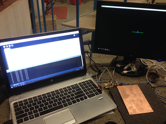
Screen Shots of the processing work
.jpg)


Download the code
.jpg)
2.jpg)
2.jpg)
2.jpg)
Final Video of the interface with 3axis Accelerometer
This time I want to do something different and related to the lab where we work. Tapan and I have decided to work for this exercise together for a similar cause.
We decided to make a warning/ informing device that gives awareness to all the users entering the lab. I decided to make a RGB light fleshing 3 different colors for open condition, open for long time and close condition for the fab lab door. The idea that we used was common but we worked differently for our assignments.
My Individual task:
My task was to make a hello button and also make a RGB LED. First I made a hello button and then made a RGB Led.
Once the boards are ready I connected it to the arduino board and then coded them one by one and then connected it individually and then added power supply.
This task was performed in steps described below:
For the input device I made another hello button board and an RGB board from the output devices.
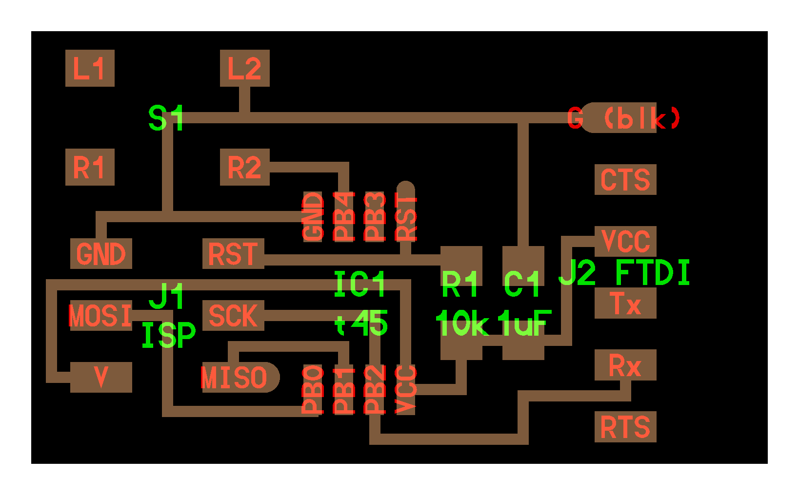
The diagrams of the circuits are :
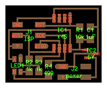
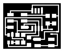
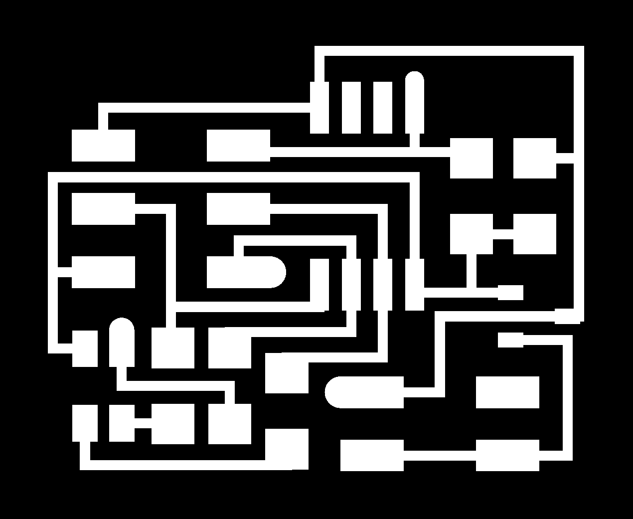
Hello Button:


RGB LED:

What I am planning to do ???
I wanted to flesh the light on the door opening. There are many people coming and visiting the lab. The door of the lab is continuously operated in terms of opening and closing. Sometimes people keep it open and forget to close the door.
So my idea was to use a RBG output board to get the signals from the button. As the connection of the button is worked out on basis of door open and close.
I needed on and off situation only so I didn't used the earlier input and output circuits.
So now I did the same process as described in week 8 for milling and soldering and then made my arduino board as the arduino ISP programmer.
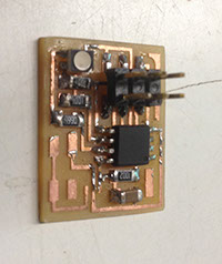
First board Hello Button:

.jpg)
Milling of the board took 10 minutes with both the traces and interior
Soldering of the board took me around 1.5 hrs a bit slow process but did it well
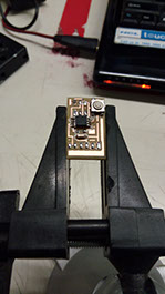
Finally the board is ready with all the components
and its ready to solder.
Second Board RGB LED:


Milling of the board took 8 minutes as the board was small
Soldering of the board is not a difficult task for me now did it in 45 minutes
Finally the board is ready with all the components
and its ready to solder.
Once all the components and boards are ready now we can do the coding of the board:
First the code is uploaded to the hello button. Its the same code downloaded from the fab archive. Once the data is uploaded in the hello switch we checked it and then the code was modified to give the digital output.
According to the new code of the serial data of the output of the button board is converted to digital output. So now the button is giving 2 signals which means on and off.
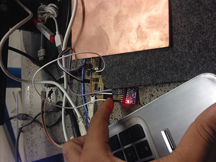
We (me and tapan) took 2 small copper plates and fixed it to he either ends of the door in such a way that when the door is closed it gives output 0. In same way if the door opens up then the result is 1.
Once the code is successfully uploaded now we will do the same thing for the RGB led.
Two opposite copper strips are fixed as mentioned above. the strips are directly connected to the button board and the button board is connected through bread board.
Basic code is applied to the RGB board. The code which was given in the fab archive was to blink the RGB led continuously with change in color at each 25 micro second. So the video shows the functioning of the board after uploading the code.

Difference in the codes for the button
.jpg)
Difference in the codes for the RGB led
.jpg)
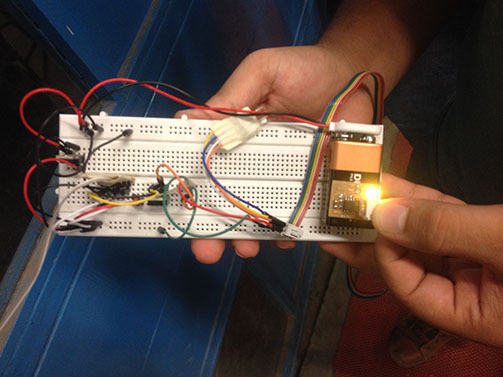
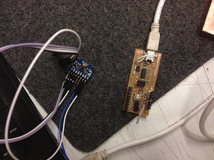
Once the coding is done I connected all the male to female wires and created the connection in the bread board.
The 9V battery is connected to the bread board. Both the sides of bread board are made ground and 9 volt supply is passed to the whole track.


All the codes are successfully uploaded and these are the few pictures of the uploaded codes and its successful working. The RGB changes its color to :
GREEN Door is just opened
ORANGE Door is opened for 2- 5 seconds
RED Door is kept open